EP4350112B1 - Vorrichtung zum öffnen und schliessen von falttüren eines möbelschranks und mit falttüren versehener möbelschrank - Google Patents
Vorrichtung zum öffnen und schliessen von falttüren eines möbelschranks und mit falttüren versehener möbelschrank Download PDFInfo
- Publication number
- EP4350112B1 EP4350112B1 EP23200150.3A EP23200150A EP4350112B1 EP 4350112 B1 EP4350112 B1 EP 4350112B1 EP 23200150 A EP23200150 A EP 23200150A EP 4350112 B1 EP4350112 B1 EP 4350112B1
- Authority
- EP
- European Patent Office
- Prior art keywords
- door
- tab
- cabinet
- guide
- folding doors
- Prior art date
- Legal status (The legal status is an assumption and is not a legal conclusion. Google has not performed a legal analysis and makes no representation as to the accuracy of the status listed.)
- Active
Links
Images





Classifications
-
- E—FIXED CONSTRUCTIONS
- E06—DOORS, WINDOWS, SHUTTERS, OR ROLLER BLINDS IN GENERAL; LADDERS
- E06B—FIXED OR MOVABLE CLOSURES FOR OPENINGS IN BUILDINGS, VEHICLES, FENCES OR LIKE ENCLOSURES IN GENERAL, e.g. DOORS, WINDOWS, BLINDS, GATES
- E06B3/00—Window sashes, door leaves, or like elements for closing wall or like openings; Layout of fixed or moving closures, e.g. windows in wall or like openings; Features of rigidly-mounted outer frames relating to the mounting of wing frames
- E06B3/32—Arrangements of wings characterised by the manner of movement; Arrangements of movable wings in openings; Features of wings or frames relating solely to the manner of movement of the wing
- E06B3/48—Wings connected at their edges, e.g. foldable wings
- E06B3/481—Wings foldable in a zig-zag manner or bi-fold wings
- E06B3/482—Wings foldable in a zig-zag manner or bi-fold wings specially adapted for furniture
-
- E—FIXED CONSTRUCTIONS
- E05—LOCKS; KEYS; WINDOW OR DOOR FITTINGS; SAFES
- E05D—HINGES OR SUSPENSION DEVICES FOR DOORS, WINDOWS OR WINGS
- E05D15/00—Suspension arrangements for wings
- E05D15/26—Suspension arrangements for wings for folding wings
- E05D15/264—Suspension arrangements for wings for folding wings for bi-fold wings
-
- E—FIXED CONSTRUCTIONS
- E05—LOCKS; KEYS; WINDOW OR DOOR FITTINGS; SAFES
- E05Y—INDEXING SCHEME ASSOCIATED WITH SUBCLASSES E05D AND E05F, RELATING TO CONSTRUCTION ELEMENTS, ELECTRIC CONTROL, POWER SUPPLY, POWER SIGNAL OR TRANSMISSION, USER INTERFACES, MOUNTING OR COUPLING, DETAILS, ACCESSORIES, AUXILIARY OPERATIONS NOT OTHERWISE PROVIDED FOR, APPLICATION THEREOF
- E05Y2201/00—Constructional elements; Accessories therefor
- E05Y2201/60—Suspension or transmission members; Accessories therefor
- E05Y2201/622—Suspension or transmission members elements
- E05Y2201/684—Rails; Tracks
-
- E—FIXED CONSTRUCTIONS
- E05—LOCKS; KEYS; WINDOW OR DOOR FITTINGS; SAFES
- E05Y—INDEXING SCHEME ASSOCIATED WITH SUBCLASSES E05D AND E05F, RELATING TO CONSTRUCTION ELEMENTS, ELECTRIC CONTROL, POWER SUPPLY, POWER SIGNAL OR TRANSMISSION, USER INTERFACES, MOUNTING OR COUPLING, DETAILS, ACCESSORIES, AUXILIARY OPERATIONS NOT OTHERWISE PROVIDED FOR, APPLICATION THEREOF
- E05Y2800/00—Details, accessories and auxiliary operations not otherwise provided for
- E05Y2800/26—Form or shape
- E05Y2800/266—Form or shape curved
-
- E—FIXED CONSTRUCTIONS
- E05—LOCKS; KEYS; WINDOW OR DOOR FITTINGS; SAFES
- E05Y—INDEXING SCHEME ASSOCIATED WITH SUBCLASSES E05D AND E05F, RELATING TO CONSTRUCTION ELEMENTS, ELECTRIC CONTROL, POWER SUPPLY, POWER SIGNAL OR TRANSMISSION, USER INTERFACES, MOUNTING OR COUPLING, DETAILS, ACCESSORIES, AUXILIARY OPERATIONS NOT OTHERWISE PROVIDED FOR, APPLICATION THEREOF
- E05Y2900/00—Application of doors, windows, wings or fittings thereof
- E05Y2900/20—Application of doors, windows, wings or fittings thereof for furniture, e.g. cabinets
Definitions
- the present invention concerns an improved device for opening and closing folding doors of a furniture cabinet.
- the invention also relates to the furniture cabinet provided with these folding doors.
- the field of the invention relates to systems used to open and close doors with a folding movement, for wardrobes, kitchen cabinets and other cabinets for furnishing in general.
- Conventional doors with a folding movement have a first door hinged to a shoulder of the cabinet, provided with upper trolleys and lower runners that engage in respective sliding tracks positioned inside said cabinet.
- a second door is hinged to this first door, which is also provided with upper trolleys and lower parts sliding on the same tracks used for the trolleys and runners of the first door.
- Prior art folding doors as described above, have the drawback that, even in their completely open position, they are arranged at around 90° with respect to the inner compartment of the cabinet, causing the formation of an obstruction that prevents the compartment of the cabinet to be fully used.
- German patent application DE19646199A1 describes a folding door consisting of two panels that can rotate relative to each other.
- a drive motor is connected to the first panel that has a fixed pin support.
- the motor is arranged in an external guide close to the upper edge of the first panel, so that it can translate between two limit stops.
- It is connected to at least one flexible driving element, through an element that slides by means of at least one of its vertical shafts.
- the driving element is arranged in a horizontal curved guide, fixed to a fixed structure above the upper edge of the first panel, at a level such that it does not limit the movement of the door.
- the Japanese utility model JPS5982186U describes a folding door formed by two panels connected so that they can be folded freely at the adjacent edges on the room side; a panel of the door has its free end fixed in a rotating manner to the upper and lower frames and the end of the other panel is free.
- the panels are movable along the guide tracks of the upper and lower frames.
- the guide track of the lower frame is located in the end part of the track in the position of the end part of the pin of the door spring housing.
- the panel is rotatable towards the outside of the room and the hinged end of the panel is rotated by a drive motor.
- the main object of the present invention is to provide a new device suitable to allow doors with a folding movement to be able to rotate up to an angle of above 90° on the related shoulder of the cabinet, so as to avoid the formation of obstructions in the inner space of the compartment thereof.
- a further object of the present invention is to provide a device that is reliable and long lasting.
- the device of the invention makes it possible to overcome the conventional need to provide tracks inside the cabinet, so as to allow folding doors to slide until the compartment for access to the inside of the cabinet is completely free.
- the device of the invention is used to guide the opening and closing movements of two folding doors, a first door 2 and a second door 3 respectively, used to close the compartment 4 of a cabinet 5.
- the first door 2 is hinged, on its side 2a, to the shoulder 6 of the cabinet 5 by means of hinges 7, of the type designed to allow the door to open up to 180° with respect to the initial position closing the compartment 4 of the cabinet 5 ( Fig. 8 ).
- hinges 7 are of the type described and illustrated in the patent application IT102016000012259, filed on 5 February 2016 by the same Applicant.
- the side 2b of the door 2, opposite its hinging side 2a, is instead hinged to the corresponding side 3b of the second door 3 by means of central hinges 31, preferably of spring loaded thrust type, suitable to facilitate the folding opening and closing movements of the door 3 on the door 2.
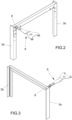
- the side 3a of the door 3, opposite its side 3b, is instead provided, at its upper end 8, with the guide arm 9 of the device 1 illustrated in Figs. 2 and 3 .
- the device 1 of the invention is mounted fixed above and on the outside of the top 13 of the cabinet 1 and comprises a central guide 10 extending rectilinearly, at the opposite ends of which respective curvilinear or arched guide sections, 11 and 12 respectively, are mounted.
- the device 1 has a separable structure, in which the guides 10, 11 and 12 are not in a single piece but are separate from one another.
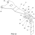
- the guide arm 9 of the device of the invention has an L-shaped bracket 14 that, on the vertical side, is fixed to the upper end 8 of the door 3, while on the horizontal side it is hinged, by means of a pin 15 engaged in a respective hole 17a, on a first metal tab 16, bearing the hole 17b for passage of the pin 15. This allows rotation of the door 3 with respect to the door 2 in the direction of the arrows F1 in Fig. 5 .
- the same tab 16 is also provided with holes 18, 19 and a slot 20 oriented crosswise with respect to the same axis.
- the guide arm 9 further comprises a second metal tab 21 fixed superimposed on the first tab 16 by means of pins 22, 23 suitable to be inserted sliding in the corresponding slotted holes 24, 25 of the tab 21.
- the same tab 21 also has a hole 26 suitable to receive the stud 27 of an eccentric 28, inserted in the slot 20 of the tab 16.
- the arrangement described allows the tab 21 to translate longitudinally with respect to the tab 16 in the direction of the arrows F2 in Fig. 4 .
- the end of the guide arm 9 facing the guides 10, 11, 12 of the device of the invention is provided with sliding means, which, in the example illustrated in Figs. 4 and 5 , consist of bearings 29 and 30 that engage sliding inside the aforesaid guides 10, 11 and 12.
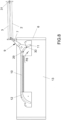
- both the doors 2 and 3 move away from the cabinet 5 by sliding of the bearings 29, 30 of the guide arm 9, first in the direction of the arrow F4 in Fig. 6 , inside the curvilinear guide section 12, and subsequently in the direction of the arrow F5 in Fig. 7 , inside the rectilinear central guide section 10.
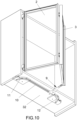
- the guides 10, 11, 12 and the arm 9 of the device of the invention could also be underneath or on the outside of the base 32 of the cabinet 5, as illustrated in Fig. 10 .
- the objects of the invention are achieved also arranging the device 1 on the surfaces of the top 13 and of the base 32 facing the inside of the compartment 4 of the cabinet 5, thanks to the presence of the described composition with arched or curvilinear ends of the sliding guide of the bearings 29, 30, at the sides of the rectilinear section of the device 1.
Landscapes
- Engineering & Computer Science (AREA)
- Mechanical Engineering (AREA)
- Civil Engineering (AREA)
- Structural Engineering (AREA)
- Extensible Doors And Revolving Doors (AREA)
Claims (7)
- Eine Vorrichtung zum Öffnen und Schließen von Falttüren (2, 3), welche eine Seite (2a) einer ersten Tür (2) umfassen, die durch Scharniere (7) mit der Schulter (6) eines Schranks (5) klappbar verbunden ist, wobei die entgegengesetzte Seite (2b) der gleichen Tür (2) mit Hilfe von Scharnieren (31) mit einer zweiten Tür (3) verbunden ist; eine geformte Führung, welche durch einen geradlinigen Abschnitt (10) gebildet wird, der an den entgegengesetzten Enden jeweils mit entsprechenden, bogenförmigen oder gekrümmten Führungsabschnitten (11) und (12) verbunden ist; einen Führungsarm (9), welcher an einem Ende jeweils mit dem entsprechenden Ende (8) der genannten Tür (3) klappbar verbunden ist und am entgegengesetzten Ende entsprechende Gleitelemente (29, 30) des genannten Arms (9) innen in der genannten geformten Führung trägt; wobei der genannte Führungsarm (9) jeweils einen entsprechenden Lappen (16) umfasst, welcher übereinanderliegend und längs gleitend in Bezug auf einen Lappen (21) angeordnet ist; und diese Vorrichtung dadurch gekennzeichnet wird, dass der genannte Lappen (16) Öffnungen (18, 19) aufweist, die in der Längsrichtung des genannten Lappens (16) ausgekerbt sind, wobei ein Einschnitt (20) ebenfalls in Bezug auf die genannte Längsachse quergerichtet ist.
- Die Vorrichtung gemäß Anspruch 1, dadurch gekennzeichnet, dass der genannte Führungsarm (9) einen Exzenter (28) aufweist, welcher sich in dem entsprechenden Einschnitt (20) befindet, der auf dem genannten Lappen (16) gebildet wird, wobei der genannte Exzenter (28) ebenfalls einen Stift (27) umfasst, der in der Öffnung (26) des Lappens (21) untergebracht ist.
- Die Vorrichtung gemäß Anspruch 2, dadurch gekennzeichnet, dass sie Zapfen (22, 23) umfasst, welche in den genannten geschlitzten Öffnungen (24, 25) des Lappens (21) sowie in entsprechenden Öffnungen (18, 19) des Lappens (16) untergebracht sind, die geeignet sind, die Kupplung zwischen den genannten Lappen (16, 21) herzustellen, indem sie in der Längsrichtung der genannten Lappen (16, 21) gleiten.
- Die Vorrichtung gemäß Anspruch 3, dadurch gekennzeichnet, dass der genannte Führungsarm (9) desweiteren eine Klammer (14) umfasst, welche mit einem entsprechenden Zapfen (15) für die Drehverbindung der zweiten Tür (3) mit dem genannten Arm (9) ausgestattet ist.
- Die Vorrichtung gemäß Anspruch 4, dadurch gekennzeichnet, dass die genannten Scharniere (31) des Typs mit gefederter Verschiebung sind, welche geeignet sind, die Faltöffnungs- und -Schließungsbewegungen der Tür (3) auf die Tür (2) zu vereinfachen.
- Ein Schrank des Typs, welcher mit Falttüren (2, 3) ausgerüstet ist, dadurch gekennzeichnet, dass er mit der Vorrichtung gemäß einem oder mehreren der vorausgegangenen Ansprüche ausgestattet ist.
- Der Schrank gemäß Anspruch 6, dadurch gekennzeichnet, dass die genannte Vorrichtung jeweils oberseitig (13) oder am Boden (32) des genannten Schranks (5) angeordnet ist.
Applications Claiming Priority (1)
| Application Number | Priority Date | Filing Date | Title |
|---|---|---|---|
| IT102022000020601A IT202200020601A1 (it) | 2022-10-06 | 2022-10-06 | Dispositivo di tipo migliorato per la movimentazione di ante a libro di mobile per arredamento e mobile per arredamento provvisto di queste ante a libro |
Publications (3)
| Publication Number | Publication Date |
|---|---|
| EP4350112A1 EP4350112A1 (de) | 2024-04-10 |
| EP4350112C0 EP4350112C0 (de) | 2025-01-01 |
| EP4350112B1 true EP4350112B1 (de) | 2025-01-01 |
Family
ID=84942758
Family Applications (1)
| Application Number | Title | Priority Date | Filing Date |
|---|---|---|---|
| EP23200150.3A Active EP4350112B1 (de) | 2022-10-06 | 2023-09-27 | Vorrichtung zum öffnen und schliessen von falttüren eines möbelschranks und mit falttüren versehener möbelschrank |
Country Status (3)
| Country | Link |
|---|---|
| EP (1) | EP4350112B1 (de) |
| ES (1) | ES3019437T3 (de) |
| IT (1) | IT202200020601A1 (de) |
Families Citing this family (1)
| Publication number | Priority date | Publication date | Assignee | Title |
|---|---|---|---|---|
| EP4729736A1 (de) | 2024-10-15 | 2026-04-22 | Danco S.p.A. | Mechanismus zum öffnen von falttüren |
Family Cites Families (2)
| Publication number | Priority date | Publication date | Assignee | Title |
|---|---|---|---|---|
| JPS5982186U (ja) * | 1982-11-24 | 1984-06-02 | 立山アルミニウム工業株式会社 | 折り畳み扉の開閉装置 |
| AT405861B (de) * | 1995-11-09 | 1999-12-27 | Liberda Viktor | Schwenktor bzw. falttor |
-
2022
- 2022-10-06 IT IT102022000020601A patent/IT202200020601A1/it unknown
-
2023
- 2023-09-27 ES ES23200150T patent/ES3019437T3/es active Active
- 2023-09-27 EP EP23200150.3A patent/EP4350112B1/de active Active
Also Published As
| Publication number | Publication date |
|---|---|
| ES3019437T3 (en) | 2025-05-20 |
| EP4350112A1 (de) | 2024-04-10 |
| EP4350112C0 (de) | 2025-01-01 |
| IT202200020601A1 (it) | 2024-04-06 |
Similar Documents
| Publication | Publication Date | Title |
|---|---|---|
| US6170195B1 (en) | Door assembly | |
| CN108286860B (zh) | 冰箱 | |
| CN108253711B (zh) | 冰箱 | |
| CN112282539B (zh) | 带有挡板的冰箱 | |
| CN108106312B (zh) | 冰箱 | |
| EP2924212B1 (de) | Schiebetüröffnungs- und -schliessvorrichtung | |
| US20120180395A1 (en) | Door opening/closing system and catch therefor | |
| EP4006282A1 (de) | Scharnieranordnung mit ablenkplatte und kühlschrank damit | |
| EP2025854A2 (de) | Bündig schliessende, in einer Wandaussparung angeordnete Schiebetür | |
| EP4350112A1 (de) | Vorrichtung zum öffnen und schliessen von falttüren eines möbelschranks und mit falttüren versehener möbelschrank | |
| CN112282546B (zh) | 带有挡板的铰链组件及具有其的冰箱 | |
| RU2337600C2 (ru) | Выдвижной ящик | |
| CN108286862B (zh) | 嵌入式铰链装置 | |
| CN114059873A (zh) | 铰链组件及具有其的家具 | |
| EP1234940A2 (de) | Unsichtbares Gleitscharnier | |
| KR102002259B1 (ko) | 가구용 홀딩 도어 장치 | |
| CN108286861B (zh) | 冰箱 | |
| CN108204180B (zh) | 嵌入式铰链装置 | |
| KR100639209B1 (ko) | 수배전반 함체의 슬라이딩 도어장치 | |
| WO2026067012A1 (zh) | 自闭合铰链 | |
| JP5649530B2 (ja) | 隠し蝶番 | |
| CN108252601B (zh) | 嵌入式铰链装置 | |
| US3260303A (en) | Multi-panel sliding door structure | |
| CN108104636A (zh) | 嵌入式铰链装置 | |
| KR102179836B1 (ko) | 이중 레일 구조의 폴딩 도어 개폐장치 |
Legal Events
| Date | Code | Title | Description |
|---|---|---|---|
| PUAI | Public reference made under article 153(3) epc to a published international application that has entered the european phase |
Free format text: ORIGINAL CODE: 0009012 |
|
| STAA | Information on the status of an ep patent application or granted ep patent |
Free format text: STATUS: THE APPLICATION HAS BEEN PUBLISHED |
|
| AK | Designated contracting states |
Kind code of ref document: A1 Designated state(s): AL AT BE BG CH CY CZ DE DK EE ES FI FR GB GR HR HU IE IS IT LI LT LU LV MC ME MK MT NL NO PL PT RO RS SE SI SK SM TR |
|
| STAA | Information on the status of an ep patent application or granted ep patent |
Free format text: STATUS: REQUEST FOR EXAMINATION WAS MADE |
|
| 17P | Request for examination filed |
Effective date: 20240610 |
|
| GRAP | Despatch of communication of intention to grant a patent |
Free format text: ORIGINAL CODE: EPIDOSNIGR1 |
|
| STAA | Information on the status of an ep patent application or granted ep patent |
Free format text: STATUS: GRANT OF PATENT IS INTENDED |
|
| INTG | Intention to grant announced |
Effective date: 20240909 |
|
| GRAS | Grant fee paid |
Free format text: ORIGINAL CODE: EPIDOSNIGR3 |
|
| GRAA | (expected) grant |
Free format text: ORIGINAL CODE: 0009210 |
|
| STAA | Information on the status of an ep patent application or granted ep patent |
Free format text: STATUS: THE PATENT HAS BEEN GRANTED |
|
| AK | Designated contracting states |
Kind code of ref document: B1 Designated state(s): AL AT BE BG CH CY CZ DE DK EE ES FI FR GB GR HR HU IE IS IT LI LT LU LV MC ME MK MT NL NO PL PT RO RS SE SI SK SM TR |
|
| REG | Reference to a national code |
Ref country code: GB Ref legal event code: FG4D |
|
| REG | Reference to a national code |
Ref country code: DE Ref legal event code: R096 Ref document number: 602023001587 Country of ref document: DE |
|
| REG | Reference to a national code |
Ref country code: CH Ref legal event code: EP |
|
| REG | Reference to a national code |
Ref country code: IE Ref legal event code: FG4D |
|
| U01 | Request for unitary effect filed |
Effective date: 20250123 |
|
| U07 | Unitary effect registered |
Designated state(s): AT BE BG DE DK EE FI FR IT LT LU LV MT NL PT RO SE SI Effective date: 20250129 |
|
| REG | Reference to a national code |
Ref country code: ES Ref legal event code: FG2A Ref document number: 3019437 Country of ref document: ES Kind code of ref document: T3 Effective date: 20250520 |
|
| PG25 | Lapsed in a contracting state [announced via postgrant information from national office to epo] |
Ref country code: PL Free format text: LAPSE BECAUSE OF FAILURE TO SUBMIT A TRANSLATION OF THE DESCRIPTION OR TO PAY THE FEE WITHIN THE PRESCRIBED TIME-LIMIT Effective date: 20250101 |
|
| PG25 | Lapsed in a contracting state [announced via postgrant information from national office to epo] |
Ref country code: IS Free format text: LAPSE BECAUSE OF FAILURE TO SUBMIT A TRANSLATION OF THE DESCRIPTION OR TO PAY THE FEE WITHIN THE PRESCRIBED TIME-LIMIT Effective date: 20250501 Ref country code: NO Free format text: LAPSE BECAUSE OF FAILURE TO SUBMIT A TRANSLATION OF THE DESCRIPTION OR TO PAY THE FEE WITHIN THE PRESCRIBED TIME-LIMIT Effective date: 20250401 |
|
| PG25 | Lapsed in a contracting state [announced via postgrant information from national office to epo] |
Ref country code: HR Free format text: LAPSE BECAUSE OF FAILURE TO SUBMIT A TRANSLATION OF THE DESCRIPTION OR TO PAY THE FEE WITHIN THE PRESCRIBED TIME-LIMIT Effective date: 20250101 |
|
| PG25 | Lapsed in a contracting state [announced via postgrant information from national office to epo] |
Ref country code: GR Free format text: LAPSE BECAUSE OF FAILURE TO SUBMIT A TRANSLATION OF THE DESCRIPTION OR TO PAY THE FEE WITHIN THE PRESCRIBED TIME-LIMIT Effective date: 20250402 |
|
| PG25 | Lapsed in a contracting state [announced via postgrant information from national office to epo] |
Ref country code: CZ Free format text: LAPSE BECAUSE OF FAILURE TO SUBMIT A TRANSLATION OF THE DESCRIPTION OR TO PAY THE FEE WITHIN THE PRESCRIBED TIME-LIMIT Effective date: 20250101 |
|
| PG25 | Lapsed in a contracting state [announced via postgrant information from national office to epo] |
Ref country code: SM Free format text: LAPSE BECAUSE OF FAILURE TO SUBMIT A TRANSLATION OF THE DESCRIPTION OR TO PAY THE FEE WITHIN THE PRESCRIBED TIME-LIMIT Effective date: 20250101 |
|
| U1N | Appointed representative for the unitary patent procedure changed after the registration of the unitary effect |
Representative=s name: PRAXI INTELLECTUAL PROPERTY MILANO; IT |
|
| PG25 | Lapsed in a contracting state [announced via postgrant information from national office to epo] |
Ref country code: SK Free format text: LAPSE BECAUSE OF FAILURE TO SUBMIT A TRANSLATION OF THE DESCRIPTION OR TO PAY THE FEE WITHIN THE PRESCRIBED TIME-LIMIT Effective date: 20250101 |
|
| PLBE | No opposition filed within time limit |
Free format text: ORIGINAL CODE: 0009261 |
|
| STAA | Information on the status of an ep patent application or granted ep patent |
Free format text: STATUS: NO OPPOSITION FILED WITHIN TIME LIMIT |
|
| 26N | No opposition filed |
Effective date: 20251002 |