EP4350141A1 - Rotor pour une éolienne, éolienne et module de rotor - Google Patents
Rotor pour une éolienne, éolienne et module de rotor Download PDFInfo
- Publication number
- EP4350141A1 EP4350141A1 EP23202278.0A EP23202278A EP4350141A1 EP 4350141 A1 EP4350141 A1 EP 4350141A1 EP 23202278 A EP23202278 A EP 23202278A EP 4350141 A1 EP4350141 A1 EP 4350141A1
- Authority
- EP
- European Patent Office
- Prior art keywords
- rotor
- modules
- hub
- flow
- wind
- Prior art date
- Legal status (The legal status is an assumption and is not a legal conclusion. Google has not performed a legal analysis and makes no representation as to the accuracy of the status listed.)
- Withdrawn
Links
- 239000007769 metal material Substances 0.000 claims description 3
- 238000010276 construction Methods 0.000 description 6
- 238000009434 installation Methods 0.000 description 4
- 238000004519 manufacturing process Methods 0.000 description 3
- 239000000463 material Substances 0.000 description 3
- 229910052751 metal Inorganic materials 0.000 description 3
- 239000002184 metal Substances 0.000 description 3
- 238000005452 bending Methods 0.000 description 2
- 238000009826 distribution Methods 0.000 description 2
- 229910000831 Steel Inorganic materials 0.000 description 1
- 238000009825 accumulation Methods 0.000 description 1
- 229910052782 aluminium Inorganic materials 0.000 description 1
- XAGFODPZIPBFFR-UHFFFAOYSA-N aluminium Chemical compound [Al] XAGFODPZIPBFFR-UHFFFAOYSA-N 0.000 description 1
- 238000013459 approach Methods 0.000 description 1
- 230000001419 dependent effect Effects 0.000 description 1
- 238000005516 engineering process Methods 0.000 description 1
- 238000000034 method Methods 0.000 description 1
- 230000000414 obstructive effect Effects 0.000 description 1
- 238000005457 optimization Methods 0.000 description 1
- 230000002093 peripheral effect Effects 0.000 description 1
- 238000010248 power generation Methods 0.000 description 1
- 239000010959 steel Substances 0.000 description 1
- 229920001169 thermoplastic Polymers 0.000 description 1
- 239000004416 thermosoftening plastic Substances 0.000 description 1
- 238000003466 welding Methods 0.000 description 1
Images


Classifications
-
- F—MECHANICAL ENGINEERING; LIGHTING; HEATING; WEAPONS; BLASTING
- F03—MACHINES OR ENGINES FOR LIQUIDS; WIND, SPRING, OR WEIGHT MOTORS; PRODUCING MECHANICAL POWER OR A REACTIVE PROPULSIVE THRUST, NOT OTHERWISE PROVIDED FOR
- F03D—WIND MOTORS
- F03D1/00—Wind motors with rotation axis substantially parallel to the air flow entering the rotor
- F03D1/06—Rotors
- F03D1/0602—Rotors having rotating wind-guiding means, e.g. associated with the hub
-
- F—MECHANICAL ENGINEERING; LIGHTING; HEATING; WEAPONS; BLASTING
- F03—MACHINES OR ENGINES FOR LIQUIDS; WIND, SPRING, OR WEIGHT MOTORS; PRODUCING MECHANICAL POWER OR A REACTIVE PROPULSIVE THRUST, NOT OTHERWISE PROVIDED FOR
- F03D—WIND MOTORS
- F03D1/00—Wind motors with rotation axis substantially parallel to the air flow entering the rotor
- F03D1/06—Rotors
- F03D1/0608—Rotors characterised by their aerodynamic shape
Definitions
- the invention relates to a rotor for a wind turbine comprising a central rotor hub which defines a rotor axis, and a rotor disk arranged around the rotor hub with a plurality of flow channels, wherein the flow channels are each formed by flow surfaces with a radially aligned leading edge and guide surfaces with a circumferentially aligned leading edge, wherein the flow surfaces are aligned obliquely to the rotor axis in order to cause a torque about the rotor axis when the wind flows against the rotor.
- the invention further relates to a wind turbine and a rotor module.
- the invention is based on the object of developing a construction method for such systems that is as simple and cost-effective as possible.
- a rotor for a wind turbine comprising a central rotor hub, which defines a rotor axis, and a rotor disk arranged around the rotor hub with a plurality of flow channels, wherein the flow channels are each formed by flow surfaces with a radially aligned leading edge and guide surfaces with a circumferentially aligned leading edge, wherein the flow surfaces are aligned obliquely to the rotor axis in order to cause a torque about the rotor axis when the wind flows against the rotor, which is further developed in that the rotor disk is constructed from rotor modules essentially in the shape of a segment of a circle, wherein the rotor modules are each attached to the rotor hub and adjacent rotor modules are connected to one another.
- a key advantage of the invention is that the rotor modules can be pre-assembled in suitable workshop environments and yet can be easily transported to the installation site of a wind turbine, where they can be assembled into the complete rotor with relatively little effort. In contrast to the pre-assembly of the complete rotor, which is usually several meters in diameter, this eliminates the need for complex special transport, unless the size of the rotor prohibits this option from the outset. In contrast to the construction of the rotor from individual parts at the installation site of the wind turbine, however, the difficult and weather-dependent assembly time outdoors is reduced, which significantly speeds up installation and significantly reduces the associated costs.
- the rotor according to the invention has in particular a front side facing the wind and a rear side facing away from the wind, wherein the flow channels extend in particular from the front to the rear of the rotor.
- the flow channels circumscribed by the front and rear of the rotor Areas are preferably congruent and essentially circular or polygonal.
- a further advantage of the invention is that the rotor modules can be manufactured in series production and using suitable, even large and stationary machine tools, so that the unit costs can be significantly reduced through economies of scale. It is also advantageous if the rotor modules are at least partially identical in construction. For example, within the scope of the invention, it is conceivable that only three or fewer different designs are provided for all rotor modules of a rotor.
- a detachable connection of the rotor modules to one another and/or a detachable fastening of the rotor modules to the rotor hub is fundamentally advantageous in order to be able to quickly and easily replace a damaged rotor module or remove it for repair if necessary.
- a preferred embodiment of the invention is characterized in that the rotor modules each have supports on the edge. This ensures sufficient inherent stability of the individual rotor modules to enable, for example, transport lying upright.
- a simple and firm connection of the rotor modules in the rotor is made possible by connecting adjacent rotor modules to one another via the supports.
- the edge supports of the two adjacent modules are preferably arranged abutting one another along their length, thus enabling a simple and permanent connection, for example by screwing, riveting or welding the two supports.
- each rotor module has four supports, which are mounted in pairs on the front and rear sides of the module, each with respect to the Intended flow direction along the rotor axis when installed as intended in the rotor according to the invention.
- the supports are preferably designed as elongated support profiles. Examples of well-known L-, T-, double-T-, round or rectangular profiles are conceivable, which are known to be easy and inexpensive to manufacture from all suitable materials and in the required length.
- the flow surfaces and/or the guide surfaces are formed from flat sheets.
- Flat sheets made of a metal material are particularly suitable here, as they can be brought into the desired shape easily, inexpensively and with high precision using the well-known sheet metal bending process.
- it is easy to provide angled tabs by means of which surfaces that are perpendicular to one another, for example a guide surface and a flow surface, can be securely and permanently connected to one another.
- the rotor modules are preferably secured to the rotor hub by suitable clamping means in order to at least partially absorb wind pressure forces acting on the rotor modules in the direction of the rotor axis and to divert them to the rotor hub.
- suitable clamping means particularly with larger rotors according to the invention, in which the modules have a radial length of several meters, considerable wind pressure along the rotor axis, i.e. transverse to the main plane of the rotor, is to be expected.
- the clamping means according to the invention relieve the fastening of the rotor modules to the rotor hub and thus allow a simple, cost-effective and yet safe design.
- Suitable tensioning means within the scope of the invention are, for example, tensioning cables which engage the rotor modules at a distance from the rotor hub and run radially inwards on the one hand and, on the other hand, obliquely to the rotor axis, against the wind towards the rotor hub.
- the rotor hub has Preferably, there is a pressure-resistant extension extending beyond the rotor disk parallel to the rotor axis to which the tensioning cables can be attached.
- the object underlying the invention is also achieved by a wind turbine with a rotor according to the invention.
- the rotor hub preferably has a cross-section that is larger than a cross-section of the machine house that is intended to face the incoming wind. This prevents the incoming wind from building up between the rotor and the machine house, so that the air flowing through the rotor can flow away freely.
- the rotor hub has a flow-guiding front side in order to divert the incoming wind radially outwards into the area of the rotor disk. This increases the flow speed and thus the energy yield at least in the radially inner flow channels.
- This can be, for example, a conical or rounded tip that is rotationally symmetrical to the rotor axis and extends at least partially over the cross-section of the rotor hub facing the wind.
- the object underlying the invention is further achieved by a rotor module for a rotor according to the invention.
- FIG. 1a schematically a perspective view
- Fig. 1b schematically shows a side view.
- the wind turbine 1 comprises a rotor 2 which is rotated about a Fig. 1b
- the rotor axis 22 shown as a dashed line is rotatably mounted.
- a machine house 3 is provided, which can contain, for example, a drive train coupled to the rotor 2 with a drive shaft, generator, bearings and, if necessary, a gearbox.
- the machine house 3 with the rotor 2 is arranged on a tower 4 and can be rotated about the vertical axis of the tower 4 to align the rotor 2 with the wind.
- the tower 4 is suitably founded, for example on a schematically shown foundation 5.
- a schematically shown foundation 5 Depending on the size of the wind turbine 1, however, another installation is also conceivable within the scope of the invention, for example on buildings or on existing masts.
- the rotor 2 of the wind turbine 1 according to the invention has its own inventive content. Further details of the exemplary rotor 2 according to the invention can be seen from a schematic plan view, which is shown in Fig.2 is shown.
- the rotor 2 has a rotor hub 20 which is arranged in the center of a rotor disk 26.
- the rotor disk 26 is formed from a plurality of rotor modules 27, 27' which are fastened to the rotor hub 20 on the one hand and connected to the two adjacent rotor modules 27, 27' on the other.
- rotor modules 27, 27' are fastened to the rotor hub 20 on the one hand and connected to the two adjacent rotor modules 27, 27' on the other.
- the rotor hub 20 has a conical cap 24 in order to deflect the incoming wind from the center of the rotor 2 radially outward toward the rotor disk 26 with as little resistance as possible.
- the cross-sectional area of the rotor hub 22 is selected such that the machine housing 3 located behind it is simultaneously shielded, so that obstructive accumulation of the flowing air is avoided both in front of the rotor hub 22 and between the rotor 2 and the machine housing 3.
- the tensioning cables 29 run in a radial direction from the outer circumference of the rotor disk 26 to the rotor axis 22 and are evenly distributed over the circumference so that radial tensile forces compensate each other.
- the rotor hub 20 has an axially arranged, pressure-stable support rod 28, to the tip of which the tensioning cables 29 are attached.
- a rotor 2 In the specifically described embodiment of a rotor 2 according to the invention, twelve rotor modules 27, 27' are provided in the rotor disk 26. This results in a maximum width of approximately 2.5 m and a length of less than 5 m for the rotor modules 27, 27' with a rotor diameter of 10 m, for example.
- the depth of the rotor modules 27, 27' corresponds to the depth of the rotor disk 26 and is generally significantly less than the maximum width or the length.
- the number of rotor modules 27, 27' is preferably dimensioned such that the maximum width of the individual rotor modules 27, 27' remains compatible with the dimensional limits for width and height prescribed for standard trucks. Accordingly, rotors 2 according to the invention with a larger diameter generally have more rotor modules 27, 27' than those with a smaller diameter.
- the exemplary rotor 2 according to the invention has a sixfold rotational symmetry, so that there are only two different types of construction for the rotor modules 27, 27', which are installed alternately in the circumferential direction of the rotor 2.
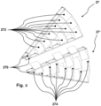
- An exemplary rotor module 27 according to the invention of one type of construction and an exemplary rotor module 27 ⁇ according to the invention of the other type of construction are shown schematically in Fig.3 shown.
- the rotor modules 27; 27' each comprise four peripheral supports 270, which extend essentially radially in the complete rotor 2. For better For the sake of clarity of the drawings, not all of the supports 270 shown are provided with reference symbols.
- the supports 270 are largely responsible for the mechanical stability of the rotor modules 27, 27', so that the rotor modules 27, 27' are preferably attached to the rotor hub 20 with the supports 270. For the same reason, adjacent rotor modules 27, 27' are preferably connected to one another by connecting the supports 270 of the corresponding rotor modules 27, 27' arranged next to one another. Any suitable connection technology is conceivable for this within the scope of the invention, whereby detachable connections can be advantageous in selected individual cases.
- tensioning cables 29 or other tensioning means are provided for dissipating axial compressive forces
- the tensioning cables 29 or tensioning means run in axial projection to the supports 270. In this way, bending and/or torsional loads within the rotor modules 27, 27' and the rotor disk 26 or the rotor 2 as a whole can be significantly reduced.
- Guide surfaces 274 are attached between the supports 270 of the rotor modules 27, 27', the front edge of which is aligned along the circumference with respect to the complete rotor 2 and the surface of which runs essentially parallel to the rotor axis 22.
- the guide surfaces 274 are thus only minimally exposed to the intended incoming wind and contribute significantly to the stiffening of the rotor modules 27, 27' between the supports 270. However, they divide the rotor disk 26 into several concentric rings and are preferably all distributed at an approximately constant radial distance from one another.
- Flow surfaces 272 are arranged between the guide surfaces 274, the front edge of which runs radially to the complete rotor 2 and which are aligned obliquely to the rotor axis 22. Due to the large number of flow surfaces 272 and guide surfaces 274 shown, only selected examples are provided with reference symbols in the drawings.
- the flow surfaces 272 and the guide surfaces 274 are each made as bent sheet metal parts from flat sheet metal, for example from aluminum, steel or another suitable metallic material.
- flat sheet metal for example from aluminum, steel or another suitable metallic material.
- other materials can also be used within the scope of the invention without affecting the general inventive concept, for example thermoplastics or fiber-reinforced materials.
- the flow surfaces 272 and/or guide surfaces 274 are designed, for example, as one-piece components, which in particular reduces the assembly effort and keeps the number of components low overall.
- a design made up of several individual components can also be advantageous, which are then smaller and therefore easier to manufacture.
- Two adjacent flow surfaces 272 and the two adjacent guide surfaces 274 form a flow channel that runs in the circumferential direction of the rotor 2 at an angle to the rotor axis 22.
- the corresponding deflection of the incoming wind generates a torque that is available for energy generation.
- the two exemplary types of rotor modules 27, 27' differ essentially only in the distribution of the flow surfaces 272 and thus the distribution of the flow channels over the rotor disk 26. It is particularly advantageous if the flow channels all have approximately the same cross-sectional area.
Landscapes
- Engineering & Computer Science (AREA)
- Life Sciences & Earth Sciences (AREA)
- Sustainable Development (AREA)
- Sustainable Energy (AREA)
- Chemical & Material Sciences (AREA)
- Combustion & Propulsion (AREA)
- Mechanical Engineering (AREA)
- General Engineering & Computer Science (AREA)
- Physics & Mathematics (AREA)
- Fluid Mechanics (AREA)
- Wind Motors (AREA)
Applications Claiming Priority (1)
| Application Number | Priority Date | Filing Date | Title |
|---|---|---|---|
| DE102022125857.2A DE102022125857A1 (de) | 2022-10-06 | 2022-10-06 | Rotor für eine Windenergieanlage, Windenergieanlage und Rotormodul |
Publications (1)
| Publication Number | Publication Date |
|---|---|
| EP4350141A1 true EP4350141A1 (fr) | 2024-04-10 |
Family
ID=88297288
Family Applications (1)
| Application Number | Title | Priority Date | Filing Date |
|---|---|---|---|
| EP23202278.0A Withdrawn EP4350141A1 (fr) | 2022-10-06 | 2023-10-06 | Rotor pour une éolienne, éolienne et module de rotor |
Country Status (2)
| Country | Link |
|---|---|
| EP (1) | EP4350141A1 (fr) |
| DE (1) | DE102022125857A1 (fr) |
Citations (4)
| Publication number | Priority date | Publication date | Assignee | Title |
|---|---|---|---|---|
| DE2909781A1 (de) * | 1979-03-13 | 1980-09-25 | Karlheinz Ohlberg | Fluegelrotor, insbesondere fuer windmotoren (windkraftwerke) mit in mindestens 2 konzentrisch aufgeteilte kreisringflaechen |
| DE2951635A1 (de) * | 1979-12-21 | 1981-07-02 | Karlheinz Ing.(grad.) 4220 Dinslaken Ohlberg | Windkraftwerk, dessen rotor bei sturm selbstaetig aus dem wind pendelt |
| FR2575790A3 (fr) * | 1985-01-08 | 1986-07-11 | Tournier Pierre | Roue d'eolienne |
| US20130177425A1 (en) * | 2010-05-13 | 2013-07-11 | Resa Intellectual Property Pty Ltd | Turbine blade assembly |
Family Cites Families (10)
| Publication number | Priority date | Publication date | Assignee | Title |
|---|---|---|---|---|
| DE371459C (de) * | 1921-11-13 | 1923-03-15 | Paul Wagner | Laufrad fuer Windturbinen mit allseitig geschlossenen Kanaelen, welche in mehreren konzentrisch umeinandergelagerten, mit Schaufeln versehenen Ringen angeordnet sind |
| US4111601A (en) * | 1977-02-02 | 1978-09-05 | Richard Joseph G | Adjustable windmill |
| IE790335L (en) * | 1979-03-12 | 1980-09-12 | Gilchrist Timothy M | Wind turbine rotor |
| PL204631B1 (pl) * | 2001-08-08 | 2010-01-29 | Wieser Gudrun | Siłownia wiatrowa do pozyskiwania energii |
| DE102006027885A1 (de) * | 2006-06-16 | 2007-12-20 | Meyer, Ullrich, Dr. Ing. | Speichen-Windrad |
| DE102008025719B4 (de) * | 2008-05-29 | 2012-06-14 | Klaus Fichtner | Windkraftanlage |
| US20120121429A1 (en) * | 2010-11-16 | 2012-05-17 | Herbert Williams | Concentric ring wind turbine |
| DE102015102461A1 (de) * | 2014-02-28 | 2015-09-03 | Horst Löwe | Windkraftanlage mit Vorstage an den Rotorblättern |
| WO2020157764A1 (fr) * | 2019-02-01 | 2020-08-06 | Veeramani Chitravelu | Rotor d'éolienne de type à voile |
| KR102335566B1 (ko) * | 2020-06-26 | 2021-12-07 | 주식회사 씨엔스카이텍 | 일체형 회전체의 고출력 발전 와류풍차장치 |
-
2022
- 2022-10-06 DE DE102022125857.2A patent/DE102022125857A1/de not_active Withdrawn
-
2023
- 2023-10-06 EP EP23202278.0A patent/EP4350141A1/fr not_active Withdrawn
Patent Citations (4)
| Publication number | Priority date | Publication date | Assignee | Title |
|---|---|---|---|---|
| DE2909781A1 (de) * | 1979-03-13 | 1980-09-25 | Karlheinz Ohlberg | Fluegelrotor, insbesondere fuer windmotoren (windkraftwerke) mit in mindestens 2 konzentrisch aufgeteilte kreisringflaechen |
| DE2951635A1 (de) * | 1979-12-21 | 1981-07-02 | Karlheinz Ing.(grad.) 4220 Dinslaken Ohlberg | Windkraftwerk, dessen rotor bei sturm selbstaetig aus dem wind pendelt |
| FR2575790A3 (fr) * | 1985-01-08 | 1986-07-11 | Tournier Pierre | Roue d'eolienne |
| US20130177425A1 (en) * | 2010-05-13 | 2013-07-11 | Resa Intellectual Property Pty Ltd | Turbine blade assembly |
Also Published As
| Publication number | Publication date |
|---|---|
| DE102022125857A1 (de) | 2024-04-11 |
Similar Documents
| Publication | Publication Date | Title |
|---|---|---|
| EP2932095B1 (fr) | Élément de transition destiné à être disposé entre des portions exécutées différemment d'une tour d'éolienne et tour d'éolienne équipée dudit élément de transition | |
| EP1002949A2 (fr) | Eolienne à axe vertical | |
| EP3455493B1 (fr) | Pale de rotor d'éolienne et éolienne équipée de cette dernière | |
| DE102012106772A1 (de) | Modularer Turm einer Windkraftanlage | |
| EP2815130A2 (fr) | Diffuseur, ventilateur comportant un tel diffuseur et appareil comprenant de tels ventilateurs | |
| EP2035694A1 (fr) | Moyeu de rotor d'une éolienne | |
| WO2018019832A1 (fr) | Élément de raccordement permettant de raccorder des sections de tour, section de tour, tour, éolienne ainsi que procédé de fabrication d'une section de tour et de raccordement de sections de tour | |
| DE102017120487A1 (de) | Turm einer Windenergieanlage und Verfahren zum Herstellen eines Sektionssegments für einen solchen Turm | |
| WO2011107589A1 (fr) | Tour pour éolienne | |
| EP3472462B1 (fr) | Eolienne à structure modulaire | |
| DE202011003456U1 (de) | Anlage zur Nutzung von Windkraft | |
| DE102013221681B4 (de) | Hybridturm einer Windturbine | |
| DE102009048984A1 (de) | Vorrichtung einer Unterkonstruktion für Windenergie-Turmanlagen | |
| DE102008044807A1 (de) | Strömungskonverter, insbesondere Windkraftkonverter | |
| EP2826957A1 (fr) | Rotor pour une turbomachine thermique | |
| EP2064444A2 (fr) | Installation d'énergie éolienne | |
| EP4350141A1 (fr) | Rotor pour une éolienne, éolienne et module de rotor | |
| EP4065798B1 (fr) | Structure en treillis pour une tour d'éolienne, et tour d'éolienne | |
| DE202009000125U1 (de) | Windkraftanlage mit einem ersten Rotor | |
| DE102005047961A1 (de) | Hybridturm | |
| DE202013003148U1 (de) | Flügelelement für einen Savonius-Rotor, Savonius-Rotor und Kleinwindkraftanlage | |
| EP3034864A1 (fr) | Moyeu de rotor pour un rotor presentant un axe de rotor d'une eolienne | |
| DE102016112876A1 (de) | Durchströmwindkraftanlage | |
| EP4069971A1 (fr) | Pièce de transition pour une tour d'une turbine éolienne et tour d'une turbine éolienne | |
| DE2448623A1 (de) | Ventilatoren mit rad und beschaufelung |
Legal Events
| Date | Code | Title | Description |
|---|---|---|---|
| PUAI | Public reference made under article 153(3) epc to a published international application that has entered the european phase |
Free format text: ORIGINAL CODE: 0009012 |
|
| STAA | Information on the status of an ep patent application or granted ep patent |
Free format text: STATUS: THE APPLICATION HAS BEEN PUBLISHED |
|
| AK | Designated contracting states |
Kind code of ref document: A1 Designated state(s): AL AT BE BG CH CY CZ DE DK EE ES FI FR GB GR HR HU IE IS IT LI LT LU LV MC ME MK MT NL NO PL PT RO RS SE SI SK SM TR |
|
| STAA | Information on the status of an ep patent application or granted ep patent |
Free format text: STATUS: THE APPLICATION IS DEEMED TO BE WITHDRAWN |
|
| 18D | Application deemed to be withdrawn |
Effective date: 20241011 |