EP4350164B1 - Scheibenbremse für schienenfahrzeuge - Google Patents
Scheibenbremse für schienenfahrzeuge Download PDFInfo
- Publication number
- EP4350164B1 EP4350164B1 EP23201639.4A EP23201639A EP4350164B1 EP 4350164 B1 EP4350164 B1 EP 4350164B1 EP 23201639 A EP23201639 A EP 23201639A EP 4350164 B1 EP4350164 B1 EP 4350164B1
- Authority
- EP
- European Patent Office
- Prior art keywords
- friction
- friction elements
- disc
- railway vehicles
- disc brake
- Prior art date
- Legal status (The legal status is an assumption and is not a legal conclusion. Google has not performed a legal analysis and makes no representation as to the accuracy of the status listed.)
- Active
Links
Images


Classifications
-
- F—MECHANICAL ENGINEERING; LIGHTING; HEATING; WEAPONS; BLASTING
- F16—ENGINEERING ELEMENTS AND UNITS; GENERAL MEASURES FOR PRODUCING AND MAINTAINING EFFECTIVE FUNCTIONING OF MACHINES OR INSTALLATIONS; THERMAL INSULATION IN GENERAL
- F16D—COUPLINGS FOR TRANSMITTING ROTATION; CLUTCHES; BRAKES
- F16D65/00—Parts or details
- F16D65/02—Braking members; Mounting thereof
- F16D65/04—Bands, shoes or pads; Pivots or supporting members therefor
- F16D65/092—Bands, shoes or pads; Pivots or supporting members therefor for axially-engaging brakes, e.g. disc brakes
- F16D65/095—Pivots or supporting members therefor
- F16D65/097—Resilient means interposed between pads and supporting members or other brake parts
- F16D65/0971—Resilient means interposed between pads and supporting members or other brake parts transmitting brake actuation force, e.g. elements interposed between brake piston and pad
-
- F—MECHANICAL ENGINEERING; LIGHTING; HEATING; WEAPONS; BLASTING
- F16—ENGINEERING ELEMENTS AND UNITS; GENERAL MEASURES FOR PRODUCING AND MAINTAINING EFFECTIVE FUNCTIONING OF MACHINES OR INSTALLATIONS; THERMAL INSULATION IN GENERAL
- F16D—COUPLINGS FOR TRANSMITTING ROTATION; CLUTCHES; BRAKES
- F16D55/00—Brakes with substantially-radial braking surfaces pressed together in axial direction, e.g. disc brakes
- F16D55/02—Brakes with substantially-radial braking surfaces pressed together in axial direction, e.g. disc brakes with axially-movable discs or pads pressed against axially-located rotating members
- F16D55/22—Brakes with substantially-radial braking surfaces pressed together in axial direction, e.g. disc brakes with axially-movable discs or pads pressed against axially-located rotating members by clamping an axially-located rotating disc between movable braking members, e.g. movable brake discs or brake pads
- F16D55/224—Brakes with substantially-radial braking surfaces pressed together in axial direction, e.g. disc brakes with axially-movable discs or pads pressed against axially-located rotating members by clamping an axially-located rotating disc between movable braking members, e.g. movable brake discs or brake pads with a common actuating member for the braking members
- F16D55/225—Brakes with substantially-radial braking surfaces pressed together in axial direction, e.g. disc brakes with axially-movable discs or pads pressed against axially-located rotating members by clamping an axially-located rotating disc between movable braking members, e.g. movable brake discs or brake pads with a common actuating member for the braking members the braking members being brake pads
-
- F—MECHANICAL ENGINEERING; LIGHTING; HEATING; WEAPONS; BLASTING
- F16—ENGINEERING ELEMENTS AND UNITS; GENERAL MEASURES FOR PRODUCING AND MAINTAINING EFFECTIVE FUNCTIONING OF MACHINES OR INSTALLATIONS; THERMAL INSULATION IN GENERAL
- F16D—COUPLINGS FOR TRANSMITTING ROTATION; CLUTCHES; BRAKES
- F16D65/00—Parts or details
- F16D65/0006—Noise or vibration control
-
- F—MECHANICAL ENGINEERING; LIGHTING; HEATING; WEAPONS; BLASTING
- F16—ENGINEERING ELEMENTS AND UNITS; GENERAL MEASURES FOR PRODUCING AND MAINTAINING EFFECTIVE FUNCTIONING OF MACHINES OR INSTALLATIONS; THERMAL INSULATION IN GENERAL
- F16D—COUPLINGS FOR TRANSMITTING ROTATION; CLUTCHES; BRAKES
- F16D65/00—Parts or details
- F16D65/02—Braking members; Mounting thereof
- F16D65/12—Discs; Drums for disc brakes
- F16D65/122—Discs; Drums for disc brakes adapted for mounting of friction pads
-
- F—MECHANICAL ENGINEERING; LIGHTING; HEATING; WEAPONS; BLASTING
- F16—ENGINEERING ELEMENTS AND UNITS; GENERAL MEASURES FOR PRODUCING AND MAINTAINING EFFECTIVE FUNCTIONING OF MACHINES OR INSTALLATIONS; THERMAL INSULATION IN GENERAL
- F16D—COUPLINGS FOR TRANSMITTING ROTATION; CLUTCHES; BRAKES
- F16D69/00—Friction linings; Attachment thereof; Selection of coacting friction substances or surfaces
- F16D69/02—Composition of linings ; Methods of manufacturing
- F16D69/025—Compositions based on an organic binder
-
- F—MECHANICAL ENGINEERING; LIGHTING; HEATING; WEAPONS; BLASTING
- F16—ENGINEERING ELEMENTS AND UNITS; GENERAL MEASURES FOR PRODUCING AND MAINTAINING EFFECTIVE FUNCTIONING OF MACHINES OR INSTALLATIONS; THERMAL INSULATION IN GENERAL
- F16D—COUPLINGS FOR TRANSMITTING ROTATION; CLUTCHES; BRAKES
- F16D69/00—Friction linings; Attachment thereof; Selection of coacting friction substances or surfaces
- F16D69/02—Composition of linings ; Methods of manufacturing
- F16D69/027—Compositions based on metals or inorganic oxides
-
- F—MECHANICAL ENGINEERING; LIGHTING; HEATING; WEAPONS; BLASTING
- F16—ENGINEERING ELEMENTS AND UNITS; GENERAL MEASURES FOR PRODUCING AND MAINTAINING EFFECTIVE FUNCTIONING OF MACHINES OR INSTALLATIONS; THERMAL INSULATION IN GENERAL
- F16D—COUPLINGS FOR TRANSMITTING ROTATION; CLUTCHES; BRAKES
- F16D69/00—Friction linings; Attachment thereof; Selection of coacting friction substances or surfaces
- F16D69/04—Attachment of linings
-
- B—PERFORMING OPERATIONS; TRANSPORTING
- B61—RAILWAYS
- B61H—BRAKES OR OTHER RETARDING DEVICES SPECIALLY ADAPTED FOR RAIL VEHICLES; ARRANGEMENT OR DISPOSITION THEREOF IN RAIL VEHICLES
- B61H5/00—Applications or arrangements of brakes with substantially radial braking surfaces pressed together in axial direction, e.g. disc brakes
-
- F—MECHANICAL ENGINEERING; LIGHTING; HEATING; WEAPONS; BLASTING
- F16—ENGINEERING ELEMENTS AND UNITS; GENERAL MEASURES FOR PRODUCING AND MAINTAINING EFFECTIVE FUNCTIONING OF MACHINES OR INSTALLATIONS; THERMAL INSULATION IN GENERAL
- F16D—COUPLINGS FOR TRANSMITTING ROTATION; CLUTCHES; BRAKES
- F16D65/00—Parts or details
- F16D65/02—Braking members; Mounting thereof
- F16D2065/13—Parts or details of discs or drums
- F16D2065/1304—Structure
- F16D2065/1324—Structure carrying friction elements
-
- F—MECHANICAL ENGINEERING; LIGHTING; HEATING; WEAPONS; BLASTING
- F16—ENGINEERING ELEMENTS AND UNITS; GENERAL MEASURES FOR PRODUCING AND MAINTAINING EFFECTIVE FUNCTIONING OF MACHINES OR INSTALLATIONS; THERMAL INSULATION IN GENERAL
- F16D—COUPLINGS FOR TRANSMITTING ROTATION; CLUTCHES; BRAKES
- F16D65/00—Parts or details
- F16D65/02—Braking members; Mounting thereof
- F16D2065/13—Parts or details of discs or drums
- F16D2065/134—Connection
- F16D2065/1392—Connection elements
-
- F—MECHANICAL ENGINEERING; LIGHTING; HEATING; WEAPONS; BLASTING
- F16—ENGINEERING ELEMENTS AND UNITS; GENERAL MEASURES FOR PRODUCING AND MAINTAINING EFFECTIVE FUNCTIONING OF MACHINES OR INSTALLATIONS; THERMAL INSULATION IN GENERAL
- F16D—COUPLINGS FOR TRANSMITTING ROTATION; CLUTCHES; BRAKES
- F16D69/00—Friction linings; Attachment thereof; Selection of coacting friction substances or surfaces
- F16D69/04—Attachment of linings
- F16D2069/0425—Attachment methods or devices
- F16D2069/0433—Connecting elements not integral with the braking member, e.g. bolts, rivets
-
- F—MECHANICAL ENGINEERING; LIGHTING; HEATING; WEAPONS; BLASTING
- F16—ENGINEERING ELEMENTS AND UNITS; GENERAL MEASURES FOR PRODUCING AND MAINTAINING EFFECTIVE FUNCTIONING OF MACHINES OR INSTALLATIONS; THERMAL INSULATION IN GENERAL
- F16D—COUPLINGS FOR TRANSMITTING ROTATION; CLUTCHES; BRAKES
- F16D2200/00—Materials; Production methods therefor
- F16D2200/0004—Materials; Production methods therefor metallic
- F16D2200/0008—Ferro
-
- F—MECHANICAL ENGINEERING; LIGHTING; HEATING; WEAPONS; BLASTING
- F16—ENGINEERING ELEMENTS AND UNITS; GENERAL MEASURES FOR PRODUCING AND MAINTAINING EFFECTIVE FUNCTIONING OF MACHINES OR INSTALLATIONS; THERMAL INSULATION IN GENERAL
- F16D—COUPLINGS FOR TRANSMITTING ROTATION; CLUTCHES; BRAKES
- F16D2200/00—Materials; Production methods therefor
- F16D2200/0004—Materials; Production methods therefor metallic
- F16D2200/0026—Non-ferro
-
- F—MECHANICAL ENGINEERING; LIGHTING; HEATING; WEAPONS; BLASTING
- F16—ENGINEERING ELEMENTS AND UNITS; GENERAL MEASURES FOR PRODUCING AND MAINTAINING EFFECTIVE FUNCTIONING OF MACHINES OR INSTALLATIONS; THERMAL INSULATION IN GENERAL
- F16D—COUPLINGS FOR TRANSMITTING ROTATION; CLUTCHES; BRAKES
- F16D2200/00—Materials; Production methods therefor
- F16D2200/0034—Materials; Production methods therefor non-metallic
- F16D2200/0052—Carbon
-
- F—MECHANICAL ENGINEERING; LIGHTING; HEATING; WEAPONS; BLASTING
- F16—ENGINEERING ELEMENTS AND UNITS; GENERAL MEASURES FOR PRODUCING AND MAINTAINING EFFECTIVE FUNCTIONING OF MACHINES OR INSTALLATIONS; THERMAL INSULATION IN GENERAL
- F16D—COUPLINGS FOR TRANSMITTING ROTATION; CLUTCHES; BRAKES
- F16D2200/00—Materials; Production methods therefor
- F16D2200/0034—Materials; Production methods therefor non-metallic
- F16D2200/0056—Elastomers
-
- F—MECHANICAL ENGINEERING; LIGHTING; HEATING; WEAPONS; BLASTING
- F16—ENGINEERING ELEMENTS AND UNITS; GENERAL MEASURES FOR PRODUCING AND MAINTAINING EFFECTIVE FUNCTIONING OF MACHINES OR INSTALLATIONS; THERMAL INSULATION IN GENERAL
- F16D—COUPLINGS FOR TRANSMITTING ROTATION; CLUTCHES; BRAKES
- F16D55/00—Brakes with substantially-radial braking surfaces pressed together in axial direction, e.g. disc brakes
- F16D55/02—Brakes with substantially-radial braking surfaces pressed together in axial direction, e.g. disc brakes with axially-movable discs or pads pressed against axially-located rotating members
- F16D55/22—Brakes with substantially-radial braking surfaces pressed together in axial direction, e.g. disc brakes with axially-movable discs or pads pressed against axially-located rotating members by clamping an axially-located rotating disc between movable braking members, e.g. movable brake discs or brake pads
Definitions
- the present invention relates to a disc brake for railway vehicles.
- the present invention is advantageously, but not exclusively, applied to medium/low speed railway vehicles.
- medium/low speed trains mean trains whose maximum speed is equal to 220 Km/h.
- each pad comprises a plurality of friction elements having reduced dimensions, instead of only one friction element having greater dimensions.
- each pad is substantially constituted by a main base plate and by a plurality of friction elements fixed to the base plate.
- each of the friction elements is composed of a sheet and of a friction insert fixed in an irreversible manner to the sheet.
- the low noise has increasingly become an important discriminating factor for choosing the disc brakes to use. This is particularly true for the medium/low speed trains programmed for making a high number of stops, such as for example undergrounds, regional or intercity trains.
- the friction elements are arranged in arched rows which, in use, are superimposed on respective concentric lines of the disc on which the pad acts and, substantially, the friction elements of the outermost rows have greater dimensions than the friction elements of the innermost rows.
- the friction elements of each row have to act on a portion of surface of the disc which is partially superimposed on the portions of the surface of the disc on which friction elements of an outermost row and of an innermost row act.
- the friction elements can be coupled on the base plate in elastic condition or in rigid condition.
- the difference between these two coupling conditions depends on whether or not an elastic element, for example a Belleville washer, is interposed between the friction element and the base plate. It has been experimentally noted that should the friction elements be coupled in elastic condition, the static friction between pad and disc is worsened.
- Document EP4006373 A1 discloses a disc brake for railway vehicles with friction elements, wherein said friction elements comprise first friction elements made of a first material and second friction elements made of a second material.
- the object of the present invention is a disc brake for railway vehicles comprising a pad and a disc on which the pad acts; said pad comprising a base plate and a plurality of friction elements fixed to the base plate; said friction elements comprising first friction elements made with a first friction material and second friction elements made with a second friction material; said first friction material having a compressibility modulus (pressure necessary to compress the material by 1mm) greater than that of said second friction material by a value greater than or equal to 1 MPa, preferably 2 MPa; said first friction elements being in a higher number than said second friction elements; said pad for disc brakes for railway vehicles being characterized by the fact that an elastic element is interposed between each of said first friction elements and said base plate, and by the fact that a respective rigid spacer is interposed between each of at least part of said second friction elements and said base plate.
- elastic element means an element that has the deformation of 1 mm by applying a value less than or equal to 1 MPa
- rigid spacer means a spacer made with a material with deformation of 1mm by applying a force greater than or equal to 2 MPa.
- a respective rigid spacer is interposed between each of said second friction elements and said base plate.
- said friction elements are arranged in rows of arcuate shape and in use substantially superimposed on respective concentric lines of the disc on which the pad acts; each row of arcuate shape comprising both said first friction elements and said second friction elements.
- said first friction elements are equal to or greater in number than said second friction elements.
- said first material has a compressibility modulus of between 2 and 40 MPa
- said second material has a compressibility modulus of between 1 and 20 MPa.
- said first friction material is a sintered material and said second friction material is an organic material.
- the sintered material has a composition composed of: from 10 to 70% by weight of copper, from 5 to 50% by weight of iron, from 5 to 30% by weight of graphite, from 1 to 15% by weight of friction modifiers.
- the organic material has a composition composed of: from 5 to 30% by weight of rubber and resin, from 10 to 50% by weight of filler, from 5 to 20% by weight of graphite, from 5 to 20% by weight of friction modifiers.
- the disc brake object of the present invention is applied to low/medium speed trains.
- reference numeral 1 indicates, as a whole, a pad for disc brakes according to the present invention.
- the pad 1 comprises a base plate 2, a "dovetail" fixing element 3, which is fixed on a rear surface of the base plate 2 and designed for fixing the pad 1 to a structure of the disc brake, and a plurality of friction elements 4 fixed to the base plate 2 and arranged for exerting the pressure on the disc of the brake for producing the braking action.
- the friction elements 4 can be fixed to the plate 2 in a reversible manner or in an irreversible manner.
- the friction elements 4 are arranged along arched rows illustrated by a dashed line and indicated by 5, which in use are substantially superimposed on concentric lines of a disc D on which the pad 1 acts.
- the disc D is illustrated by a dashed line and only partially.
- the friction elements 4 are divided into four friction elements 4a made of sintered friction material and three friction elements 4b made of organic friction material. For clarity, the friction elements made of organic material 4b are represented by a dashed surface.
- the organic material of the friction elements 4b has a composition which satisfies the following conditions: from 5 to 30% by weight of rubber and resin, from 10 to 50% by weight of filler, from 5 to 20% by weight of graphite, from 5 to 20% by weight of friction modifiers.
- the organic material has a compressibility modulus of 7 MPa.
- the sintered material of the friction elements 4a has a composition which satisfies the following conditions: from 10 to 70 % by weight of copper, from 5 to 40 % by weight of iron, from 5 to 20 % by weight of graphite, from 1 to 10 % by weight of friction modifiers.
- the sintered material has a compressibility modulus of 27 MPa.
- the first material and the second material can both be sintered materials or both organic materials, as long as the conditions of compressibility modulus mentioned in the claims are respected.
- the materials of different compressibility can be obtained, besides by materials with different chemical nature, also by means of a different preparation process of a same chemical type of material.
- the friction elements 4 are arranged on three rows identifiable as an outer row Fa, an intermediate row Fb and an inner row Fc.
- the outer row Fa comprises three friction elements 4 having equal dimensions, whereas the intermediate row Fb comprises two friction elements 4 having equal dimensions and each of which has a friction surface equal to that of each of the elements of the outer row Fa.
- the inner row Fc comprises two friction elements 4 equal to each other and each of which has a friction surface less than that of each of the elements of the outer row Fa or of the intermediate row Fb.
- the friction elements 4 of each row exert their action on a portion of disc D which is superimposed on the portions of disc D on which the friction elements 4 of the subsequently outermost and innermost rows act.
- each of the friction elements 4 is composed of a sheet 6 having a flat shape, of an insert 7 made of friction material and fixed in an irreversible manner to the sheet 6, of a fixing pin 8 and of two anti-rotation plugs 9.
- a central hole 10 is obtained engaged by the fixing pin 8 and two side holes 11, each of which is engaged by a respective anti-rotation plug 9.
- the central hole 12 has a diameter greater than the side holes 13 and is obtained in the center of a respective circular recess 14 obtained, in turn, on a lower surface 2a of the base plate 2.
- the circular recess 14 houses a locking spring 12 which engages a circumferential groove obtained in the fixing pin 8.
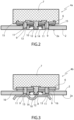
- Figures 2 and 3 illustrate two different coupling conditions.
- the coupling condition illustrated in Figure 2 provides for the presence of two Belleville washers 15 and, according to the invention, it is applied to the friction elements which provide for the sintered friction material, i.e. the material which has a greater compressibility modulus.
- Each of the two Belleville washers 15 is arranged between the sheet 6 and the base plate 2, and has a hole engaged by a respective anti-rotation plug 9.
- the coupling condition illustrated in Figure 3 provides for the presence of two rigid spacers 16 and, according to the invention, it is applied to the friction elements which provide for the organic friction material, i.e. the material which has a lesser compressibility modulus.
- Each of the two rigid spacers 16 is arranged between the sheet 6 and the base plate 2, and has a hole engaged by a respective anti-rotation plug 9.
- the two rigid spacers 16 are made of any material capable of standing the specific pressures and the heat generated during the braking, such as metals or plastic materials, in one single piece or composed of the sum of lesser thicknesses.
- the friction elements made with a low-compressibility friction material are coupled to the base plate in an elastic condition, whereas at least part of the friction elements made with a high-compressibility friction material are coupled to the base plate in a rigid condition.
- the inventors of the present invention carried out experimental tests, in order to verify the advantages in terms of static friction coefficient given by the present invention.
- the dynamometric test bench used is a BIO - PW4 Type model produced by the company SCHENCK PEGASUS GmbH, Darmstadt.
- the brake of comparison is distinguished from the brake of the present invention exclusively due to the fact that in the relative pad all the friction elements 4a and 4b are coupled to the plate with the presence of the Belleville washers.
- the brake according to the present invention provides in the relative pad for the friction elements 4a (sintered friction material - lesser compressibility) to be coupled to the base plate by means of the interposition of the Belleville washers (elastic coupling condition), whereas the friction elements 4b (organic friction material - greater compressibility) to be coupled to the base plate by means of the interposition of the rigid spacers (rigid coupling condition).
- the disc brake of comparison and the disc brake according to the invention were subjected to the experimental tests according to the above-mentioned conditions and following a procedure for verifying the static friction not referred to a particular project.
- the experimental procedure used provides, once the pads are compressed on the disc with a force between 10 and 50kN, for the dynamometric test bench to start increasing the torsional moment on the disc until the same starts rotating and, therefore, the pads start sliding with respect to the disc.
- the torsional moment on the disc continues increasing until reaching the speed of 0.8 km/h of the disc. Such speed is maintained for a period of 5 seconds.
- the ordinate shows on one single scale both the friction coefficient values and the speed values of the disc.
- the static friction coefficient is detected on the graphs at the beginning of the rotation of the disc.
- a dash-dot line was inserted for identifying the static friction values detected as described above.
- the present invention allows guaranteeing the required levels of static friction coefficient for a pad having a plurality of friction elements, while maintaining all the advantages deriving from the presence of the plurality of friction elements.
- the core of the invention lies in the different elasticity conferred to the friction elements depending on their compressibility.
Landscapes
- Engineering & Computer Science (AREA)
- General Engineering & Computer Science (AREA)
- Mechanical Engineering (AREA)
- Chemical & Material Sciences (AREA)
- Inorganic Chemistry (AREA)
- Braking Arrangements (AREA)
Claims (9)
- Scheibenbremse für Schienenfahrzeuge, umfassend einen Bremsklotz (1) und eine Scheibe (D), auf die der Bremsklotz (1) wirkt; wobei der Bremsklotz (1) eine Grundplatte (2) und eine Mehrzahl von Reibelementen (4) umfasst, die an der Grundplatte (2) fixiert sind; wobei die Reibelemente (4) erste Reibelemente (4a), die aus einem ersten Reibmaterial hergestellt sind, und zweite Reibelemente (4b), die aus einem zweiten Reibmaterial hergestellt sind, umfassen; wobei das erste Reibmaterial einen Kompressionsmodul (Druck, der notwendig ist, um das Material um 1 mm zu komprimieren) aufweist, der um einen Wert größer oder gleich 1 MPa größer als der des zweiten Reibmaterials ist; wobei die ersten Reibelemente (4a) in einer höheren Anzahl als die zweiten Reibelemente (4b) vorhanden sind; wobei der Bremsklotz (1) für Scheibenbremsen für Schienenfahrzeuge dadurch gekennzeichnet ist, dass ein jeweiliges elastisches Element (15) zwischen jedem der ersten Reibelemente (4a) und der Grundplatte (2) angeordnet ist, und dadurch, dass ein jeweiliger fester Abstandshalter (16) zwischen jedem von zumindest einem Teil der zweiten Reibelemente (4b) und der Grundplatte (2) angeordnet ist.
- Scheibenbremse für Schienenfahrzeuge nach Anspruch 1, dadurch gekennzeichnet, dass das erste Reibmaterial einen Kompressionsmodul (Druck, der notwendig ist, um das Material um 1 mm zu komprimieren) aufweist, der um einen Wert größer oder gleich 2 MPa größer als der des zweiten Reibmaterials ist.
- Scheibenbremse für Schienenfahrzeuge nach Anspruch 1 oder 2, dadurch gekennzeichnet, dass ein jeweiliger starrer Abstandshalter (16) zwischen jedem der zweiten Reibelemente (4b) und der Grundplatte (2) angeordnet ist.
- Scheibenbremse für Schienenfahrzeuge nach einem der vorangehenden Ansprüche, dadurch gekennzeichnet, dass das elastische Element aus einer Tellerfeder (15) besteht.
- Scheibenbremse für Schienenfahrzeuge nach einem der vorangehenden Ansprüche, dadurch gekennzeichnet, dass die Reibelemente (4) in Reihen von bogenförmiger Form (5) angeordnet sind und im Gebrauch im Wesentlichen auf jeweiligen konzentrischen Linien der Scheibe (D), auf die der Bremsklotz wirkt, überlagert sind; wobei jede Reihe von bogenförmiger Form (5) sowohl die ersten Reibelemente (4a) als auch die zweiten Reibelemente (4b) umfasst.
- Scheibenbremse für Schienenfahrzeuge nach Anspruch 5, dadurch gekennzeichnet, dass in jeder der bogenförmigen Reihen (5) die Anzahl der ersten Reibelemente (4a) gleich oder größer als die der zweiten Reibelemente (4b) ist.
- Scheibenbremse für Schienenfahrzeuge nach einem der vorangehenden Ansprüche, dadurch gekennzeichnet, dass das erste Material einen Kompressionsmodul zwischen 20 und 40 MPa aufweist und das zweite Material einen Kompressionsmodul zwischen 1 und 20 MPa aufweist.
- Scheibenbremse für Schienenfahrzeuge nach einem der vorangehenden Ansprüche, dadurch gekennzeichnet, dass das erste Reibmaterial ein gesintertes Material ist und das zweite Reibmaterial ein organisches Material ist.
- Scheibenbremse für Schienenfahrzeuge nach einem der vorangehenden Ansprüche, dadurch gekennzeichnet, dass sie für Niedriggeschwindigkeitszüge/Mittelgeschwindigkeitszüge vorgesehen ist.
Applications Claiming Priority (1)
| Application Number | Priority Date | Filing Date | Title |
|---|---|---|---|
| IT102022000020598A IT202200020598A1 (it) | 2022-10-06 | 2022-10-06 | Freno a disco per veicoli ferroviari |
Publications (2)
| Publication Number | Publication Date |
|---|---|
| EP4350164A1 EP4350164A1 (de) | 2024-04-10 |
| EP4350164B1 true EP4350164B1 (de) | 2025-03-19 |
Family
ID=84463007
Family Applications (1)
| Application Number | Title | Priority Date | Filing Date |
|---|---|---|---|
| EP23201639.4A Active EP4350164B1 (de) | 2022-10-06 | 2023-10-04 | Scheibenbremse für schienenfahrzeuge |
Country Status (8)
| Country | Link |
|---|---|
| US (1) | US20240117849A1 (de) |
| EP (1) | EP4350164B1 (de) |
| KR (1) | KR20240048490A (de) |
| CN (1) | CN117847118A (de) |
| ES (1) | ES3016644T3 (de) |
| FI (1) | FI4350164T3 (de) |
| IT (1) | IT202200020598A1 (de) |
| PT (1) | PT4350164T (de) |
Family Cites Families (5)
| Publication number | Priority date | Publication date | Assignee | Title |
|---|---|---|---|---|
| US4202432A (en) * | 1977-12-12 | 1980-05-13 | Komori Seisakusho Co., Ltd. | Clutch disk for use in automobile |
| JP5333205B2 (ja) * | 2009-12-28 | 2013-11-06 | 新日鐵住金株式会社 | 鉄道車両用ブレーキライニング |
| IT201800010235A1 (it) * | 2018-11-12 | 2020-05-12 | Cofren Srl | Pattino con tasselli a flessibilita' variabile per freni a disco per veicoli ferroviari |
| IT201900015309A1 (it) * | 2019-08-30 | 2021-03-02 | Cofren Srl | Pattino per freni a disco per veicoli ferroviari a media/bassa velocita' |
| IT202000028781A1 (it) * | 2020-11-27 | 2022-05-27 | Cofren Srl | Freno a disco per veicoli ferroviari |
-
2022
- 2022-10-06 IT IT102022000020598A patent/IT202200020598A1/it unknown
-
2023
- 2023-09-28 CN CN202311265405.3A patent/CN117847118A/zh active Pending
- 2023-10-03 US US18/480,333 patent/US20240117849A1/en active Pending
- 2023-10-04 PT PT232016394T patent/PT4350164T/pt unknown
- 2023-10-04 ES ES23201639T patent/ES3016644T3/es active Active
- 2023-10-04 EP EP23201639.4A patent/EP4350164B1/de active Active
- 2023-10-04 FI FIEP23201639.4T patent/FI4350164T3/fi active
- 2023-10-05 KR KR1020230132147A patent/KR20240048490A/ko active Pending
Also Published As
| Publication number | Publication date |
|---|---|
| PT4350164T (pt) | 2025-03-27 |
| CN117847118A (zh) | 2024-04-09 |
| IT202200020598A1 (it) | 2024-04-06 |
| EP4350164A1 (de) | 2024-04-10 |
| KR20240048490A (ko) | 2024-04-15 |
| US20240117849A1 (en) | 2024-04-11 |
| FI4350164T3 (fi) | 2025-04-25 |
| ES3016644T3 (en) | 2025-05-09 |
Similar Documents
| Publication | Publication Date | Title |
|---|---|---|
| US20100051393A1 (en) | Brake pad clip with integrated pad return spring and wear indicator | |
| US5341904A (en) | Railroad brake shoe | |
| CN1306182C (zh) | 具有固定卡钳的点式圆盘制动器 | |
| KR100549565B1 (ko) | 고성능 이층 마찰재 | |
| US20160108978A1 (en) | Spring-Based Disc Brake Pad Cushions | |
| CN102292566B (zh) | 活塞缩进装置、制动钳、制动系统及活塞本体的缩进方法 | |
| US20100065389A1 (en) | Carbon fiber reinforced carbon matrix composite for brake pad back plate | |
| KR20150040303A (ko) | 휠 브레이크 디스크 | |
| KR20030085135A (ko) | 마찰패드 | |
| JPWO2008090809A1 (ja) | 外周波型ブレーキディスク | |
| US4747476A (en) | Methods of making clutch driven plates | |
| EP4350164B1 (de) | Scheibenbremse für schienenfahrzeuge | |
| US4790413A (en) | Multiple disc brake | |
| JP4295716B2 (ja) | 炭素繊維複合材料及び湿式摩擦部材 | |
| US8863915B2 (en) | Disc brake pad cushions | |
| JPH0223867Y2 (de) | ||
| KR100528536B1 (ko) | 스프링유닛이 부착된 휠 | |
| KR102274648B1 (ko) | 잡음 감쇠 부재, 잡음 감쇠 부재를 갖는 자동차 디스크 브레이크 라이닝, 및 자동차 디스크 브레이크에서의 이들의 용도 | |
| PL211861B1 (pl) | Bocznie wzmacniany kolejowy klocek hamulcowy | |
| EP4006373B1 (de) | Scheibenbremse für schienenfahrzeug | |
| KR101524423B1 (ko) | 클러치 마찰 디스크 | |
| WO2019107559A1 (ja) | ディスクブレーキ | |
| JPH0218357Y2 (de) | ||
| JPH03282028A (ja) | 摩擦材料 | |
| JP4600194B2 (ja) | 鉄道車両用ブレーキディスクの締結構造及び鉄道車両用車輪 |
Legal Events
| Date | Code | Title | Description |
|---|---|---|---|
| PUAI | Public reference made under article 153(3) epc to a published international application that has entered the european phase |
Free format text: ORIGINAL CODE: 0009012 |
|
| STAA | Information on the status of an ep patent application or granted ep patent |
Free format text: STATUS: THE APPLICATION HAS BEEN PUBLISHED |
|
| STAA | Information on the status of an ep patent application or granted ep patent |
Free format text: STATUS: REQUEST FOR EXAMINATION WAS MADE |
|
| AK | Designated contracting states |
Kind code of ref document: A1 Designated state(s): AL AT BE BG CH CY CZ DE DK EE ES FI FR GB GR HR HU IE IS IT LI LT LU LV MC ME MK MT NL NO PL PT RO RS SE SI SK SM TR |
|
| 17P | Request for examination filed |
Effective date: 20240319 |
|
| RBV | Designated contracting states (corrected) |
Designated state(s): AL AT BE BG CH CY CZ DE DK EE ES FI FR GB GR HR HU IE IS IT LI LT LU LV MC ME MK MT NL NO PL PT RO RS SE SI SK SM TR |
|
| GRAP | Despatch of communication of intention to grant a patent |
Free format text: ORIGINAL CODE: EPIDOSNIGR1 |
|
| STAA | Information on the status of an ep patent application or granted ep patent |
Free format text: STATUS: GRANT OF PATENT IS INTENDED |
|
| INTG | Intention to grant announced |
Effective date: 20241011 |
|
| GRAS | Grant fee paid |
Free format text: ORIGINAL CODE: EPIDOSNIGR3 |
|
| GRAA | (expected) grant |
Free format text: ORIGINAL CODE: 0009210 |
|
| STAA | Information on the status of an ep patent application or granted ep patent |
Free format text: STATUS: THE PATENT HAS BEEN GRANTED |
|
| P01 | Opt-out of the competence of the unified patent court (upc) registered |
Free format text: CASE NUMBER: APP_2735/2025 Effective date: 20250116 |
|
| AK | Designated contracting states |
Kind code of ref document: B1 Designated state(s): AL AT BE BG CH CY CZ DE DK EE ES FI FR GB GR HR HU IE IS IT LI LT LU LV MC ME MK MT NL NO PL PT RO RS SE SI SK SM TR |
|
| REG | Reference to a national code |
Ref country code: GB Ref legal event code: FG4D |
|
| REG | Reference to a national code |
Ref country code: PT Ref legal event code: SC4A Ref document number: 4350164 Country of ref document: PT Date of ref document: 20250327 Kind code of ref document: T Free format text: AVAILABILITY OF NATIONAL TRANSLATION Effective date: 20250324 |
|
| REG | Reference to a national code |
Ref country code: CH Ref legal event code: EP |
|
| REG | Reference to a national code |
Ref country code: IE Ref legal event code: FG4D |
|
| REG | Reference to a national code |
Ref country code: DE Ref legal event code: R096 Ref document number: 602023002488 Country of ref document: DE |
|
| REG | Reference to a national code |
Ref country code: FI Ref legal event code: FGE |
|
| REG | Reference to a national code |
Ref country code: ES Ref legal event code: FG2A Ref document number: 3016644 Country of ref document: ES Kind code of ref document: T3 Effective date: 20250509 |
|
| PG25 | Lapsed in a contracting state [announced via postgrant information from national office to epo] |
Ref country code: RS Free format text: LAPSE BECAUSE OF FAILURE TO SUBMIT A TRANSLATION OF THE DESCRIPTION OR TO PAY THE FEE WITHIN THE PRESCRIBED TIME-LIMIT Effective date: 20250619 |
|
| REG | Reference to a national code |
Ref country code: LT Ref legal event code: MG9D |
|
| PG25 | Lapsed in a contracting state [announced via postgrant information from national office to epo] |
Ref country code: NO Free format text: LAPSE BECAUSE OF FAILURE TO SUBMIT A TRANSLATION OF THE DESCRIPTION OR TO PAY THE FEE WITHIN THE PRESCRIBED TIME-LIMIT Effective date: 20250619 |
|
| PG25 | Lapsed in a contracting state [announced via postgrant information from national office to epo] |
Ref country code: HR Free format text: LAPSE BECAUSE OF FAILURE TO SUBMIT A TRANSLATION OF THE DESCRIPTION OR TO PAY THE FEE WITHIN THE PRESCRIBED TIME-LIMIT Effective date: 20250319 |
|
| PG25 | Lapsed in a contracting state [announced via postgrant information from national office to epo] |
Ref country code: LV Free format text: LAPSE BECAUSE OF FAILURE TO SUBMIT A TRANSLATION OF THE DESCRIPTION OR TO PAY THE FEE WITHIN THE PRESCRIBED TIME-LIMIT Effective date: 20250319 |
|
| PG25 | Lapsed in a contracting state [announced via postgrant information from national office to epo] |
Ref country code: BG Free format text: LAPSE BECAUSE OF FAILURE TO SUBMIT A TRANSLATION OF THE DESCRIPTION OR TO PAY THE FEE WITHIN THE PRESCRIBED TIME-LIMIT Effective date: 20250319 Ref country code: GR Free format text: LAPSE BECAUSE OF FAILURE TO SUBMIT A TRANSLATION OF THE DESCRIPTION OR TO PAY THE FEE WITHIN THE PRESCRIBED TIME-LIMIT Effective date: 20250620 |
|
| REG | Reference to a national code |
Ref country code: NL Ref legal event code: MP Effective date: 20250319 |
|
| PG25 | Lapsed in a contracting state [announced via postgrant information from national office to epo] |
Ref country code: NL Free format text: LAPSE BECAUSE OF FAILURE TO SUBMIT A TRANSLATION OF THE DESCRIPTION OR TO PAY THE FEE WITHIN THE PRESCRIBED TIME-LIMIT Effective date: 20250319 |
|
| PG25 | Lapsed in a contracting state [announced via postgrant information from national office to epo] |
Ref country code: SE Free format text: LAPSE BECAUSE OF FAILURE TO SUBMIT A TRANSLATION OF THE DESCRIPTION OR TO PAY THE FEE WITHIN THE PRESCRIBED TIME-LIMIT Effective date: 20250319 |
|
| PG25 | Lapsed in a contracting state [announced via postgrant information from national office to epo] |
Ref country code: SM Free format text: LAPSE BECAUSE OF FAILURE TO SUBMIT A TRANSLATION OF THE DESCRIPTION OR TO PAY THE FEE WITHIN THE PRESCRIBED TIME-LIMIT Effective date: 20250319 |
|
| PGFP | Annual fee paid to national office [announced via postgrant information from national office to epo] |
Ref country code: FI Payment date: 20250919 Year of fee payment: 3 |
|
| PG25 | Lapsed in a contracting state [announced via postgrant information from national office to epo] |
Ref country code: IT Free format text: LAPSE BECAUSE OF FAILURE TO SUBMIT A TRANSLATION OF THE DESCRIPTION OR TO PAY THE FEE WITHIN THE PRESCRIBED TIME-LIMIT Effective date: 20250319 Ref country code: PL Free format text: LAPSE BECAUSE OF FAILURE TO SUBMIT A TRANSLATION OF THE DESCRIPTION OR TO PAY THE FEE WITHIN THE PRESCRIBED TIME-LIMIT Effective date: 20250319 |
|
| PGFP | Annual fee paid to national office [announced via postgrant information from national office to epo] |
Ref country code: TR Payment date: 20250929 Year of fee payment: 3 |
|
| PGFP | Annual fee paid to national office [announced via postgrant information from national office to epo] |
Ref country code: FR Payment date: 20250915 Year of fee payment: 3 |
|
| PG25 | Lapsed in a contracting state [announced via postgrant information from national office to epo] |
Ref country code: CZ Free format text: LAPSE BECAUSE OF FAILURE TO SUBMIT A TRANSLATION OF THE DESCRIPTION OR TO PAY THE FEE WITHIN THE PRESCRIBED TIME-LIMIT Effective date: 20250319 Ref country code: EE Free format text: LAPSE BECAUSE OF FAILURE TO SUBMIT A TRANSLATION OF THE DESCRIPTION OR TO PAY THE FEE WITHIN THE PRESCRIBED TIME-LIMIT Effective date: 20250319 |
|
| PG25 | Lapsed in a contracting state [announced via postgrant information from national office to epo] |
Ref country code: RO Free format text: LAPSE BECAUSE OF FAILURE TO SUBMIT A TRANSLATION OF THE DESCRIPTION OR TO PAY THE FEE WITHIN THE PRESCRIBED TIME-LIMIT Effective date: 20250319 |
|
| PG25 | Lapsed in a contracting state [announced via postgrant information from national office to epo] |
Ref country code: SK Free format text: LAPSE BECAUSE OF FAILURE TO SUBMIT A TRANSLATION OF THE DESCRIPTION OR TO PAY THE FEE WITHIN THE PRESCRIBED TIME-LIMIT Effective date: 20250319 |
|
| PG25 | Lapsed in a contracting state [announced via postgrant information from national office to epo] |
Ref country code: IS Free format text: LAPSE BECAUSE OF FAILURE TO SUBMIT A TRANSLATION OF THE DESCRIPTION OR TO PAY THE FEE WITHIN THE PRESCRIBED TIME-LIMIT Effective date: 20250719 |
|
| PGFP | Annual fee paid to national office [announced via postgrant information from national office to epo] |
Ref country code: PT Payment date: 20251001 Year of fee payment: 3 |
|
| REG | Reference to a national code |
Ref country code: DE Ref legal event code: R097 Ref document number: 602023002488 Country of ref document: DE |
|
| PGFP | Annual fee paid to national office [announced via postgrant information from national office to epo] |
Ref country code: DE Payment date: 20250919 Year of fee payment: 3 |
|
| PG25 | Lapsed in a contracting state [announced via postgrant information from national office to epo] |
Ref country code: DK Free format text: LAPSE BECAUSE OF FAILURE TO SUBMIT A TRANSLATION OF THE DESCRIPTION OR TO PAY THE FEE WITHIN THE PRESCRIBED TIME-LIMIT Effective date: 20250319 |
|
| PGFP | Annual fee paid to national office [announced via postgrant information from national office to epo] |
Ref country code: AT Payment date: 20260113 Year of fee payment: 3 |
|
| PLBE | No opposition filed within time limit |
Free format text: ORIGINAL CODE: 0009261 |
|
| STAA | Information on the status of an ep patent application or granted ep patent |
Free format text: STATUS: NO OPPOSITION FILED WITHIN TIME LIMIT |
|
| REG | Reference to a national code |
Ref country code: CH Ref legal event code: L10 Free format text: ST27 STATUS EVENT CODE: U-0-0-L10-L00 (AS PROVIDED BY THE NATIONAL OFFICE) Effective date: 20260128 |
|
| PGFP | Annual fee paid to national office [announced via postgrant information from national office to epo] |
Ref country code: ES Payment date: 20251113 Year of fee payment: 3 |
|
| 26N | No opposition filed |
Effective date: 20251222 |
|
| REG | Reference to a national code |
Ref country code: AT Ref legal event code: UEP Ref document number: 1777171 Country of ref document: AT Kind code of ref document: T Effective date: 20250319 |