EP4350179A1 - Élément d'étanchéité et ensemble connecteur - Google Patents
Élément d'étanchéité et ensemble connecteur Download PDFInfo
- Publication number
- EP4350179A1 EP4350179A1 EP23201268.2A EP23201268A EP4350179A1 EP 4350179 A1 EP4350179 A1 EP 4350179A1 EP 23201268 A EP23201268 A EP 23201268A EP 4350179 A1 EP4350179 A1 EP 4350179A1
- Authority
- EP
- European Patent Office
- Prior art keywords
- sealing element
- ridges
- connector
- cross
- principal face
- Prior art date
- Legal status (The legal status is an assumption and is not a legal conclusion. Google has not performed a legal analysis and makes no representation as to the accuracy of the status listed.)
- Pending
Links
Images



Classifications
-
- F—MECHANICAL ENGINEERING; LIGHTING; HEATING; WEAPONS; BLASTING
- F16—ENGINEERING ELEMENTS AND UNITS; GENERAL MEASURES FOR PRODUCING AND MAINTAINING EFFECTIVE FUNCTIONING OF MACHINES OR INSTALLATIONS; THERMAL INSULATION IN GENERAL
- F16J—PISTONS; CYLINDERS; SEALINGS
- F16J15/00—Sealings
- F16J15/02—Sealings between relatively-stationary surfaces
- F16J15/021—Sealings between relatively-stationary surfaces with elastic packing
- F16J15/022—Sealings between relatively-stationary surfaces with elastic packing characterised by structure or material
- F16J15/024—Sealings between relatively-stationary surfaces with elastic packing characterised by structure or material the packing being locally weakened in order to increase elasticity
- F16J15/025—Sealings between relatively-stationary surfaces with elastic packing characterised by structure or material the packing being locally weakened in order to increase elasticity and with at least one flexible lip
-
- H—ELECTRICITY
- H01—ELECTRIC ELEMENTS
- H01R—ELECTRICALLY-CONDUCTIVE CONNECTIONS; STRUCTURAL ASSOCIATIONS OF A PLURALITY OF MUTUALLY-INSULATED ELECTRICAL CONNECTING ELEMENTS; COUPLING DEVICES; CURRENT COLLECTORS
- H01R13/00—Details of coupling devices of the kinds covered by groups H01R12/70 or H01R24/00 - H01R33/00
- H01R13/46—Bases; Cases
- H01R13/52—Dustproof, splashproof, drip-proof, waterproof, or flameproof cases
- H01R13/5219—Sealing means between coupling parts, e.g. interfacial seal
-
- H—ELECTRICITY
- H01—ELECTRIC ELEMENTS
- H01R—ELECTRICALLY-CONDUCTIVE CONNECTIONS; STRUCTURAL ASSOCIATIONS OF A PLURALITY OF MUTUALLY-INSULATED ELECTRICAL CONNECTING ELEMENTS; COUPLING DEVICES; CURRENT COLLECTORS
- H01R13/00—Details of coupling devices of the kinds covered by groups H01R12/70 or H01R24/00 - H01R33/00
- H01R13/46—Bases; Cases
- H01R13/52—Dustproof, splashproof, drip-proof, waterproof, or flameproof cases
-
- H—ELECTRICITY
- H01—ELECTRIC ELEMENTS
- H01R—ELECTRICALLY-CONDUCTIVE CONNECTIONS; STRUCTURAL ASSOCIATIONS OF A PLURALITY OF MUTUALLY-INSULATED ELECTRICAL CONNECTING ELEMENTS; COUPLING DEVICES; CURRENT COLLECTORS
- H01R13/00—Details of coupling devices of the kinds covered by groups H01R12/70 or H01R24/00 - H01R33/00
- H01R13/40—Securing contact members in or to a base or case; Insulating of contact members
-
- H—ELECTRICITY
- H01—ELECTRIC ELEMENTS
- H01R—ELECTRICALLY-CONDUCTIVE CONNECTIONS; STRUCTURAL ASSOCIATIONS OF A PLURALITY OF MUTUALLY-INSULATED ELECTRICAL CONNECTING ELEMENTS; COUPLING DEVICES; CURRENT COLLECTORS
- H01R13/00—Details of coupling devices of the kinds covered by groups H01R12/70 or H01R24/00 - H01R33/00
- H01R13/46—Bases; Cases
- H01R13/502—Bases; Cases composed of different pieces
- H01R13/506—Bases; Cases composed of different pieces assembled by snap action of the parts
Definitions
- the present disclosure relates to a sealing element.
- the present disclosure relates to a sealing element included in a connector.
- a sealing element disclosed in Japanese Patent Laid-Open No. 9-306585 has a generally frame shape. Three streaks or ribs arranged in lines along a circumferential direction are disposed on each of the outer and inner peripheral sides of the sealing element. Sets of the streaks disposed on the inner and outer peripheral sides are configured to abut on the housings of the two connectors, respectively.
- the streaks of the sealing element are pressed between the housings of the connectors to thereby strongly come into intimate contact with the housings, while being elastically deformed, to achieve sealing between the housings.
- the present inventor recognized that sealing elements having conventional structures have problems to be overcome, and newly found the necessity to take measures against the problems. Specifically, the present inventor found that there were the following problems.
- the streak located in the center of three streaks can be compressed and deformed so as to be destroyed by loads from two housings facing each other.
- the width dimension between the housings can be decreased to increase a compressive load applied to the sealing element depending on a dimensional tolerance between connectors.
- the repulsive force of the sealing element can be excessively increased by more strongly pressing the streak in the center of the sealing element to greatly deform the streak.
- Such an increase in repulsive force allows a large introduction force to be required in an operation of mating the connector, and may cause the sealing element or the connector to be broken.
- a principal objective of the present disclosure is to provide a sealing element that more preferably enables a decrease in force required in an operation of mating a connector.
- the present inventor attempted to solve the above-described problems by addressing the problems in a new direction without solving the problems in an extension of the conventional technology.
- the invention of a sealing element for achieving the principal objective described above was accomplished.
- the present disclosure provides a sealing element including a raised region, wherein the raised region includes: a plurality of first ridges on a first principal face of the raised region; a plurality of second ridges on a second principal face of the raised region reverse or on an opposite side to the first principal face; and a central trough that is formed between the second ridges adjacent to each other and is located in a center of the second principal face, viewed in a cross-section; and at least the first ridge located in the most outer side of the plurality of first ridges is positioned to be offset against the plurality of second ridges, viewed in a cross-section.
- a force required in an operation of mating a connector can be more preferably decreased.
- a sealing element according to one embodiment of the present disclosure is described in more detail below with reference to the drawings.
- Various elements in the drawings are just described in a schematical and exemplary manner for explaining the present disclosure, and the appearances and dimensional ratios of the elements can be different from those of real things.
- viewed in cross-section means a cross-section taken along a direction orthogonal to the longitudinal direction of a sealing element (that is, the lateral direction of the sealing element).
- a feature of the present disclosure is the structure of a sealing element applicable for sealing a gap between two elements.
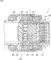
- FIG. 1 is a cross-sectional view schematically illustrating the connector assembly including the sealing element of the present disclosure.
- a connector assembly 1 includes, as main components: a first connector 200; a second connector 300 that matches with the first connector; and a sealing element 100 that is placed between the first connector 200 and the second connector 300.
- "assembly” corresponds to a composite article, a matching article, or the like including a plurality of components.
- the first connector 200 includes: an outer housing 220; and an inner housing 210 that is housed in the outer housing 220. Each of the outer housing 220 and the inner housing 210 opens in the direction of mating with the second connector 300. A contact (not illustrated) that can be electrically connected to a contact of the second connector 300 may be supported by the inner housing 210.
- the inner housing 210 may include a space around the inner housing 210, between the inner housing 210 and the outer housing 220. The first connector 200 and the second connector 300 may be mated with each other by introducing the housing 310 of the second connector 300 into such a space.
- the sealing element 100 of the present disclosure can be disposed between the first connector 200 and the second connector 300 in a state in which the first connector 200 and the second connector 300 are mated with each other. More specifically, the sealing element 100 of the present disclosure can be placed between the inner housing 210 of the first connector 200 and the housing 310 of the second connector 300 in the mating state to waterproof the contacts in the connectors.
- the sealing element 100 may be attached to surround the outer periphery of the inner housing 210 of the first connector 200.
- a groove may be formed around the outer side of the inner housing 210, and the sealing element 100 may be fitted into the groove.
- the sealing element 100 abuts on the housing 310 of the second connector 300 in a state in which the second connector 300 is introduced into the first connector 200. In such a state, the sealing element 100 is brought into intimate contact with both of the outer face of the inner housing 210 of the first connector 200 and the inner face of the housing 310 of the second connector 300, to achieve sealing between the first connector 200 and the second connector 300.
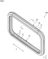
- FIG. 2 is an isometric view schematically illustrating the sealing element 100 of the present disclosure.
- the sealing element 100 may have a ring or frame shape in which the sealing element 100 can be brought into intimate contact with the outer periphery of the inner housing 210 of the first connector 200.
- the sealing element 100 may have another shape such as a long-length shape, a generally C-shape, or a generally U-shape.
- the sealing element 100 may be integrally molded by, for example, injection molding, using an elastic material (for example, silicon rubber). In the mating state, the sealing element 100 can achieve sealing between the first connector 200 and the second connector 300 in a fluid-tight manner by elastically deforming the sealing element 100 by pressing the sealing element 100 by the first connector 200 and the second connector 300.
- a feature of the present disclosure is the structure of the sealing element 100 applicable to such a connector as described above.
- the structure of the sealing element 100 of the present disclosure is described in detail below based on, as a presupposition, an aspect applied between such a first connector 200 and a second connector 300 as described above.
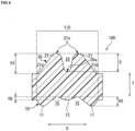
- Figure 3 is a cross-sectional view schematically illustrating a cross-section of the sealing element 100 of the present disclosure, taken along the line I-I illustrated in Figure 2 .
- the sealing element 100 of the present disclosure can be attached between the first connector 200 and the second connector 300 that match with each other.
- the sealing element 100 includes a raised region 110 including a plurality of ridges on two principal faces, reverse to each other, respectively.
- raised region refers to, in a broad sense, a region including or comprising or containing ridges or ribs in the sealing element 100, and means, in a narrow sense, a region including or comprising or containing a plurality of ridges or ribs on two principal faces, reverse to each other, in the sealing element 100, respectively.
- “raised region” is a region including ridges raised toward the first connector and ridges raised toward the second connector, and can be referred to as "ridge-containing region” and the like.
- the raised region 110 includes a first principal face 10 facing the first connector 200 and a second principal face 20 facing the second connector 300 that matches with the first connector 200.
- first principal face as used herein means a face of the raised region 110, facing the first connector 200 to which the sealing element 100 is attached before the first connector 200 and the second connector 300 are mated with each other.
- second principal face means a face of the raised region 110, facing the second connector 300 in a state in which the second connector 300 is introduced into the first connector 200, and corresponds to a face located on the reverse side of the first principal face 10.
- the first/second principal face 10, 20 is a face located in the direction of a load imposed on the sealing element 100 (that is, the thickness direction Y of the sealing element 100), and each face includes a portion that abuts on or comes into contact with the first connector 200 or the second connector 300 and can thus also be referred to as "first/second abutment face", or "first/second contact face” or "first/second face to be pressed”.
- the sealing element 100 preferably has a ring or frame shape in a case in which the sealing element 100 is disposed on the entire peripheries of the housings of the connectors.
- the first principal face 10 corresponds to the principal face of the inner peripheral side of the sealing element 100, and can thus also be regarded as the inner peripheral principal face of the sealing element 100.
- the second principal face 20 corresponds to the principal face of the outer peripheral side of the sealing element, and can thus also be regarded as the outer peripheral principal face of the sealing element.
- the sealing element 100 includes the plurality of ridges located on both the first principal face 10 and the second principal face 20 in the raised region 110.
- the sealing element 100 of the present disclosure includes a plurality of first ridges 11 present on the first principal face 10 facing the first connector 200 and a plurality of second ridges 21 present on the second principal face 20 facing the second connector 300 in the raised region 110.
- the plurality of first ridges 11 and the plurality of second ridges 21 are positioned in the raised region 110.
- “plurality of” means two or more. A description is given below with reference to the drawings, based on, as a presupposition, an exemplary aspect in which three ridges 11, 12 are included on the first principal face 10 and two second ridges 21 are included on the second principal face 20.
- the plurality of first ridges 11 and the plurality of second ridges 21 may be raised toward the first connector 200 and the second connector 300, respectively, to extend in the longitudinal direction Z of the sealing element 100 (see Figure 2 ).
- the first ridges 11 located on the first principal face 10 may be raised toward the first connector 200 to extend along the longitudinal direction Z of the sealing element 100.
- the second ridges 21 located on the second principal face 20 may be raised toward the second connector 300 to extend along the longitudinal direction Z of the sealing element 100 in a manner similar to that of the first ridges 11.
- first ridges 11 may extend along the inner periphery of the sealing element 100
- second ridges 21 may extend along the outer periphery of the sealing element 100.
- first ridges 11 and the second ridges 21 come into intimate contact with the first connector 200 and the second connector 300, respectively, to contribute to sealing between the connectors, and can thus also be referred to as first lips and second lips.
- the plurality of first ridges 11 may be arranged in lines in the lateral direction X of the sealing element 100, orthogonal to the longitudinal Z of the sealing element 100, on the first principal face 10.
- the plurality of second ridges 21 may be arranged in lines in the lateral direction X of the sealing element 100 on the second principal face 20.
- the lateral direction X of the sealing element 100 is a direction corresponding to the width direction of the sealing element, and can also be regarded as the width direction of the raised region 110.
- the width of the sealing element 100 may extend between two side faces 30 (see Fig. 3 ).
- Each of the first ridges 11 and the second ridges 21 may be raised at a similar height in the longitudinal Z of the sealing element 100.
- cross-sectional shapes of the sealing element 100 may be generally similar shapes in the longitudinal direction Z of the sealing element 100.
- a central trough 25 is formed in the center or middle of the second principal face 20, viewed in a cross-section.
- center means the center of the length of the raised region 110 in the width direction X.
- center of second principal face means the center of the width dimension of the second principal face 20.
- a center is not necessarily an exact center. Although the center can deviate depending on the size of the sealing element, for example, a deviation of around 2 mm from the exact center can be permitted.
- the central trough 25 may be formed between two second ridges 21 adjacent to each other on the second principal face 20. In other words, the two second ridges 21 adjacent to each other across the center of the second principal face may be raised to form the central trough 25 in the center of the second principal face 20.
- At least the first ridge 11 located in the most outer side of the plurality of first ridges 11 is positioned to be offset against the second ridges 21, viewed in a cross-section.
- outer side means a positional relationship based on, for example, the position of a central ridge 12 described below, in the width direction X of the raised region 110, and specifically means an end side of the raised region 110.
- Such "outer side” can also be regarded as an edge side of the sealing element 100, for example, in a case in which the whole of the sealing element 100 includes the raised region 110 as illustrated in Figure 3 .
- first ridge located in most outer side corresponds to a ridge located in the most end side of the first principal face 10, viewed in a cross-section.
- the first ridges 11 located in both the most outer sides of the first principal face 10 may be located in more outer sides than the second ridges 21, viewed in a cross-section.
- the second ridges 21 located in the most outer sides of the plurality of second ridges 21 are positioned at positions deviating toward more inner sides of the raised region 110 than the first ridges 11 located in the most outer sides of the plurality of first ridges, viewed in a cross-section.
- the first ridges 11 and the second ridges 21 are not positioned on the same line in the thickness direction Y of the sealing element.
- thickness direction of sealing element refers to a direction that is parallel to a cross-section of the sealing element 100 as illustrated in Figure 3 and orthogonal to the width direction X of the sealing element 100 (that is, a direction corresponding to a vertical direction in Figure 3 ).
- Figure 5A is a cross-sectional view schematically illustrating the sealing element of the present disclosure in a state in which a compressive load is applied to the sealing element.
- the sealing element of the present disclosure including the structure described above, the second ridges 21 are pressed by the second connector 300 when the second connector 300 is introduced into the first connector 200.
- a load imposed in the thickness direction Y of the sealing element 100 is applied to the sealing element 100 placed between the connectors.
- the second principal face 20 includes the central trough 25, and, in addition, the first ridges 11 are placed to be offset outward with respect to the second ridges 21, whereby the second ridges 21 can be elastically deformed to be bent toward the central trough 25 of the second principal face 20.
- portions just under the second ridges 21 do not abut on the first connector 200 but abut on the first ridges 11 at positions offset in the width direction X because the first ridges 11 and the second ridges 21 are not located on the same axis with respect to the thickness direction Y, and the first ridges 11 are positioned to deviate relatively outward. Therefore, when a compressive load is imposed on the second ridges 21, the second ridges 21 are compressed and deformed in a direction equivalent to the thickness direction Y, and the first ridges 11 located in an outer side, viewed in a cross-section, can be bent to lean toward the outer side. Further, the second ridges 21 can be deformed to lean toward the central trough 25 by bending the first ridges 11.
- the first ridges 11 and the second ridges 21 come into contact with the first connector 200 and second connector 300, respectively, whereby waterproofness between the connectors can be secured.
- the second ridges 21 are deformed to lean toward the central trough 25, to thereby facilitate elastic deformation of the raised region 110 in the width direction X in the case of applying a compressive load.
- Such elastic deformation in the width direction X causes a relative decrease in the heights of the second ridges 21, viewed in a cross-section, and therefore allows a reduction in the whole thickness of the sealing element 100 in the raised region 110. Therefore, the degree of the elastic deformation of the sealing element 100 in the thickness direction Y can be further reduced.
- the center of the second principal face 20 of the raised region 110 includes the central trough 25, whereby excessive repulsive force acting in the thickness direction Y of the sealing element 100 can be more preferably suppressed.
- the central trough 25 of the second principal face 20 can help the plurality of second ridges 21, located on the second principal face 20, to be preferably elastically deformed to be bent toward the center.
- the central ridge is elastically deformed to be compressed in a thickness direction Y without bending the central ridge when a load is applied in the thickness direction Y.
- the sealing element 100 of the present disclosure has the structure in which the center of the second principal face 20 includes the central trough 25, whereby the leading ends of the second ridges 21 located on both the sides of the central trough 25 can be bent toward the central trough 25 to approach each other.
- the sealing element 100 of the present disclosure can be elastically deformed not only in the thickness direction Y but also in the width direction X when a compressive load is applied to the raised region 110, and therefore, excessive repulsive force acting in the thickness direction Y of the sealing element 100 can be more preferably suppressed.
- the cross-sectional shape of the central trough 25 is not particularly limited as long as such bending of the second ridges 21 as described above is achieved.
- the cross-sectional shape may be a generally V-shape in which the central trough 25 is tapered down toward the bottom of the central trough 25 so that the width dimension of the central trough 25 is gradually reduced.
- such a cross-sectional shape allows the tip portions of the second ridges 21 to be preferably separated in a state in which a load is not applied to the second ridges 21 (that is, in which the second connector 300 is not introduced).
- the central trough 25 has a generally V-shape viewed in a cross-section, whereby application of a load from the second principal face 20 (that is, introduction of the second connector) enables the second ridges 21 to be preferably bend to lean toward the central trough 25, to more preferably elastically deform the second ridges 21 in the width direction X.
- the central trough 25 is more preferably formed to have a sufficiently great depth, viewed in a cross-section, so that the second ridges 21 can be preferably bent in the state of application of a compressive load.
- the central trough 25 is preferably a trough with a sufficient depth, formed between the two second ridges 21 independent from each other, rather than a recess formed in each second ridge 21.
- the depth D of the central trough 25, viewed in a cross-section may be equivalent to or more than the heights H1 of the second ridges 21 adjacent to the central trough 25.
- depth of central trough means a dimension between each vertex 21c of the second ridges 21 adjacent to the central trough 25 and the bottom 25a of the central trough 25, viewed in a cross-section (see Figure 4 ).
- height of second ridge means a dimension between the outer ridge start point 21d of the second ridge 21 and the vertex 21c of the second ridge 21.
- the depth D of the central trough 25 may be 50% to 120%, 60% to 115%, or 70% to 110% of the height H1 of each second ridges 21 adjacent to the central trough 25 although the depth D varies depending on the thickness, size, and the like of the sealing element 100.
- each of the plurality of second ridges 21 is bent toward the center, whereby the two second ridges 21 adjacent to each other across the central trough 25 are bent toward the central trough 25 to approach each other.
- water-stop performance can be preferably secured by the second ridge 21 in the other side.
- the second ridges 21 come into intimate contact with the second connector 300 while being bent, whereby not only the vertexes of the second ridges 21 but also the side face regions of the second ridges 21 can abut with the second connector 300. Therefore, a wider abutment region between each second ridges 21 and the second connector 300 can be secured in the sealing element 100 of the present disclosure.
- the first ridges 11 are bent in the width direction X in conjunction with the second ridges 21, whereby an abutment region between each first ridge 11 and the first connector 200 can also be further enlarged.
- the sealing element 100 and the first/second connector 200, 300 can come into intimate contact with each other in a wider region, and therefore, the sealing property of the sealing element 100 can be further improved. Accordingly, the more preferred sealing element in which both of a reduction in force of introducing a connector and the preferred sealing property are achieved can be provided in accordance with the present disclosure.
- Figure 5B is a cross-sectional view schematically illustrating an aspect in which a spacing W between the first connector 200 and the second connector 300 is less than that in Figure 5A .
- Figure 5B illustrates an aspect in which a compressive load that is larger than that in Figure 5A is imposed.
- the spacing W between the first connector 200 and the second connector 300 may be smaller depending on a dimensional tolerance between the first connector 200 and the second connector 300.
- a decrease in such a spacing W enables application of a large compressive load to the sealing element 100 in an operation of mating a connector, and an increase in repulsive force acting from the sealing element 100 onto a first connector 200 and/or a second connector 300.
- the repulsive force can result in an increase in force required in the mating operation and results in application of an excessive load on the first connector 200 and the second connector 300, causing deformation and/or breakage.
- the spacing W between the first/second connectors is small as illustrated in Figure 5B , and application of a larger load enables the second ridges 21 to be bent to further lean toward the center. It can be understood that this means that an increase in compressive load results in a further increase in the elastic deformation of the sealing element 100 in the width direction X.
- the sealing element 100 of the present disclosure is preferably elastically deformed in the width direction X, whereby the elastic deformation of the sealing element 100 in the thickness direction Y can be suppressed. Accordingly, an excessive increase in repulsive force acting in the thickness direction Y can be preferably suppressed in accordance with the structure of the sealing element 100 of the present disclosure.
- the second ridges 21 adjacent to each other across the central trough 25 may be bendable toward the center to abut on each other in a state in which a compressive load is applied to the second ridges 21 (see Figure 5B ).
- the second ridges 21 adjacent to each other may be formed so that in a state in which the second ridges 21 are bent toward the center to approach each other by a compressive load, the second ridges 21 are further bent to block the central trough 25 by a pressure applied from the outside to the sealing element, whereby the second ridges 21 can abut on each other.
- the second ridges 21 adjacent to each other may be further bent to be able to abut on each other in a case in which a load is further applied in the thickness direction Y of the sealing element 100, and/or in a case in which a pressure is applied from the end side in the width direction X of the raised region (that is, the inner and/or outer sides of the connector) to the sealing element 100.
- the second ridges 21 adjacent to each other abut on each other, whereby such two second ridges 21 come into intimate contact with the second connector 300 while supporting each other, and therefore, a sealing property offered by the sealing element 100 can be further improved.
- the plurality of first ridges 11 that are raised toward the first connector 200 may be raised at different heights, respectively.
- the first ridge 11 located in a side farther from the center of the raised region 110, viewed in a cross-section may be raised at a greater height than the first ridge 11 located in a side closer to the center.
- the central ridge 12 that is raised at a height different from the heights of the first ridges 11 is further included between any two first ridges 11 adjacent to each other, among the plurality of first ridges 11.
- the central ridge 12 is located in the center of the first principal face 10.
- the central ridge 12 is preferably raised so that the height H2 of central ridge 12 is less than the heights of the plurality of first ridges 11 (see Figure 4 ).
- the central ridge 12 may be raised so that the height H2 of the central ridge 12 located in the center, viewed in a cross-section, is the lowest, and the heights H3 of the plurality of first ridges 11 located outward from the central ridge 12 are greater than the height H2.
- the central ridge 12 is designed so that the height H2 of the central ridge 12 located in the center of the first principal face 10, viewed in a cross-section, is the lowest, whereby the central ridge 12 need not abut on the first connector 200 in a state in which a compressive load is not applied to the sealing element (that is, in a state in which the second connector is not introduced).
- Application of a compressive load to the sealing element 100 that is, introduction of the second connector 300
- the application of the compressive load from an area closer to the second principal face 20 by the introduction of the second connector 300 enables the sealing element 100 to be elastically deformed toward a lower part in the figure so that the center in the width direction X of the raised region is depressed toward the first connector 200.
- the central trough 25 of the second principal face 20 can also be deformed to be depressed toward the first connector 200 in conjunction with such deformation.
- the plurality of second ridges 21 located on both sides across the central trough 25 are elastically deformed so as to be pulled toward the central trough 25, and it becomes easy to bend the second ridges 21 toward the center.
- the above-described structure enables the sealing element 100 to be more preferably elastically deformed in the width direction X when the sealing element 100 receives a compressive load. Accordingly, the above-described structure in which the height of the raised portion of a first ridge 11 located at a position closer to the center is lower enables suppression of excessive repulsive force from the sealing element 100, and provision of a sealing element in which force required in an operation of mating a connector can be more preferably reduced.
- the central ridge 12 located in the center of the first principal face 10 and the central trough 25 of the second principal face 20 may be located in sides opposite to each other with respect to the thickness direction Y of the sealing element 100.
- the central ridge 12 of the first principal face 10 and the central trough 25 of the second principal face 20 may be located on the same line with respect to the thickness direction Y.
- the vertex 12c of the central ridge and the bottom 25a of the central trough may be located on the same imaginary line along the thickness direction Y. More preferably, the vertex 12c of the central ridge and the bottom 25a of the central trough may be located on a central line A that passes through the center of the raised region 110 and extends along the thickness direction Y, viewed in a cross-section.
- the central portion of the raised region 110 is more preferably easily elastically deformed toward the first connector 200 when a compressive load is applied in the thickness direction Y. Both the ends of the raised region 110 are relatively deformed toward the second connector 300 in conjugation with such elastic deformation. As a result, the second ridges 21 can be enabled to preferably lean toward the center. Further, the central ridge 12 and the central trough 25 are located on the central line A of the raised region 110, viewed in a cross-section, whereby both the ends of the raised region 110 can be elastically deformable to be symmetric with respect to the central line A.
- the first/second connectors 200, 300 and the sealing element 100 are more preferably brought into intimate contact with each other in both the ends of the raised region 110, and the repulsive force of the compressed and deformed sealing element 100 can be preferably inhibited from being biased in a local region.
- the repulsive force of the sealing element 100 is preferably dispersed, and repulsive force can be preferably inhibited from excessively acting on the first connector 200 and/or the second connector 300 abutting on the sealing element 100.
- force required in an operation of mating a connector can be more preferably reduced in accordance with the sealing element 100 of the present disclosure.
- the central ridge 12 and the plurality of first ridges 11 may be positioned to be offset in the width direction X of the raised region 110 with respect to the plurality of second ridges 21 located on the second principal face 20 reverse to the central ridge 12 and the plurality of first ridges 11. More specifically, the vertexes of the plurality of first ridges 11 and the central ridge 12 may be positioned to deviate in the width direction X with respect to the vertexes of the plurality of second ridges 21, viewed in a cross-section. In other words, the ridges of the first principal face, including the first ridges 11 and the central ridge 12, and the second ridges 21 need not be located on the same line with respect to the thickness direction Y of the sealing element 100.
- the ridges of the first principal face including the first ridges 11 and the central ridge 12, and the second ridges 21 may be placed on the first principal face 10 and the second principal face 20, respectively, so as to alternate, viewed in a cross-section.
- the ridges of the first principal face, including the first ridges 11 and the central ridge 12, and the second ridges 21 are positioned to be offset against each other, whereby an edge for deflection for elastic deformation in the thickness direction Y exists at a position opposite in the thickness direction of each ridge, viewed in a cross-section.
- the ridges of the first principal face, including the first ridges 11 and the central ridge 12, and the second ridge 21 are not located on the same line with respect to the thickness direction Y of the sealing element 100, viewed in a cross-section, and therefore, gaps 15 exist on a side opposite to the second ridges 21 between the first connector 200 and the sealing element 100 in a state in which no compressive load is applied.
- the ridges abutting on the connectors are pressed, and the sealing element 100 can be deformed so that the gaps 15 between the first connector 200 and the sealing element 100 become smaller.
- the ridges 11, 12 of the first principal face 10 and the second ridges 21 are positioned to be offset against each other, whereby application of a compressive load enables the sealing element 100 to be deformed so that the sealing element 100 is bent, and therefore, compressive deformation in the thickness direction Y of the ridges is reduced.
- excessive repulsive force from the sealing element 100 to the connectors, caused by the compressive deformation of the sealing element 100 can be preferably suppressed.
- the second ridges 21 adjacent to each other may be bent toward the center in a state in which a compressive load is applied, and the tip portions of the second ridges 21 may be able to abut on each other to support each other. Therefore, it is preferable to position an even number of second ridges 21 on the second principal face 20.
- two, four, or six second ridges 21 may be formed on the second principal face 20.
- a less number of (for example, two or four) second ridges 21 are preferably positioned on the second principal face 20 so that the cross-sectional area of each ridge becomes larger.
- two second ridges 21 may be placed to form the central trough 25 in the center of the second principal face 20 (see Figure 3 ).
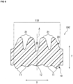
- the second principal face 20 may include four second ridges 21 (see Figure 6 ).
- the first ridges 11 more preferably include at least the central ridge 12 and first ridges 11 located on more outer both sides than the second ridges 21, viewed in a cross-section.
- the first principal face 10 preferably includes at least three first ridges 11.
- an odd number of ridges 11, 12 are positioned to be offset against each other on the first principal face 10.
- the first principal face 10 may include an odd number of ridges including an even number of first ridges 11 and one central ridge 12.
- the sealing element 100 of the present disclosure may include an even number of first ridges 11 and an even number of second ridges 21.
- the sealing element 100 may include two first ridges 11, one central ridge 12 located between the two first ridges 11, and two second ridges 21, as illustrated in Figure 3 .
- the sealing element 100 may include four first ridges 11, one central ridge 12, and four second ridges 21 so that the first ridges 11, the central ridge 12, and the second ridges 21 are positioned to be offset against each other, viewed in a cross-section.
- the cross-sectional shapes of the first ridges 11 and the second ridges 21 may have mountain shapes of which the width dimensions gradually decrease with approach to the vertexes of the ridges.
- each second ridge 21 may have an outer contour in which the slope angles of a sloped or inclined face 21b closer to the center of the second principal face and an outer sloped or inclined face 21a opposite to the sloped face 21b closer to the center, viewed in a cross-section, are different from each other.
- the cross-sectional shape of each second ridges 21 is not symmetrical, and a portion closer to the center and an outer portion in each second ridge 21 may slope at different angles.
- each second ridge 21 is line-asymmetrical with respect to an imaginary line B that passes through the vertex of each second ridge 21 and is parallel to the thickness direction Y of the sealing element (see Figure 3 ).
- the slope angle of the sloped face 21b closer to the center may be greater than the slope angle of the outer sloped face 21a.
- the angle of the outer slope may be less than the angle of the slope closer to the center.
- an outer portion may more gently slope than a portion closer to the center, viewed in a cross-section.
- each second ridge 21 includes a gentle slope in a side into which the second connector 300 is introduced, and therefore interference between the second connector 300 and the sealing element 100 in an operation of introducing the second connector 300 can be reduced. Accordingly, the second connector 300 can be more easily introduced, and force required in an operation of mating a connector can be more preferably reduced.
- each first ridge 11 may more gently slope in a portion closer to the center than in an outer portion, viewed in a cross-section.
- each first ridge 11 may have an asymmetric shape, viewed in a cross-section.
- the cross-sectional shape of each first ridge 11 is line-asymmetrical with respect to an imaginary line C that passes through the vertex of each first ridge 11 and is parallel to the thickness direction Y of the sealing element (see Figure 3 ).
- the slope angle of the sloped face 11b closer to the center may be less than the slope angle of the outer sloped face 11a.
- the cross-sectional shape of the central ridge 12 is line-symmetrical with respect to an imaginary line (corresponding to the central line A in Figure 3 ) that passes through the vertex of the central ridge 12 and is parallel to the thickness direction Y of the sealing element.
- the second connector 300 is introduced into the first connector 200 to which the sealing element 100 is attached.
- the second connector 300 is introduced into a portion closer to the second principal face 20 in a state in which a portion closer to the first principal face 10 including the first ridges 11 abuts on the first connector 200.
- each first ridge 11 has a shape in which the outer side of each first ridge 11 more steeply slopes, whereby bending of each first ridge 11 toward the center is suppressed.
- each first ridge 11 has such a cross-sectional shape as described above, whereby inhibition of unintentional movement of the sealing element 100 due to an operation of introducing or removing the second connector 300 can be enabled.
- the sealing element 100 is preferably retained on the first connector 200 by the first ridges 11, whereby easier introduction or removal of the second connector 300 can be enabled.
- the raised region 110 includes a line-symmetrical portion, viewed in a cross-section.
- the cross-sectional shape of the raised region 110 may be line-symmetrical with respect to the central line A that passes through the center of the sealing element 100 and extends in the thickness direction Y (see Figure 3 ).
- the positioning and form of the first ridges 11 and the second ridges 21 in the raised region 110, viewed in a cross-section, may be symmetrical with respect to the central line A.
- the cross-sectional shape of the raised region 110 is line-symmetrical, whereby horizontally evenly elastic deformation of the sealing element 100 in the raised region 110 in application of a compressive load is further facilitated, and local concentration of repulsive force acting due to the elastic deformation can be preferably inhibited.
- line-symmetrical is not necessarily limited to "completely line-symmetrical” but encompasses form and/or positioning that are approximately line-symmetrical.
- the sealing element 100 including the raised region 110 may be line-symmetrical as a whole, viewed in a cross-section.
- the cross-sectional shape of the sealing element 100 may have a shape that is line-symmetrical with respect to the central line A, as illustrated in Figure 3 or 4 .
- the sealing element 100 further includes an extension region 120 contiguous to the raised region 110 (see Figures 7A and 7B ).
- the extension region 120 may extend from the at least one end of the raised region 110, viewed in a cross-section.
- Such an extension region 120 is a region that does not include a ridge extending from the raised region 110, and can thus also be referred to as "non-raised region", “ridge-free region”, and the like.
- the extension region 120 is included, whereby a region in which the sealing element 100, and the first connector 200 and/or the second connector 300 can come into contact with each other is enlarged, and therefore, it is possible to achieve improvement in sealing property and to more preferably prevent the deviation of the sealing element 100 due to introduction or removal of the connectors.
- the sealing element of the present disclosure including a structure further including the extension region 120 as well as the raised region 110, can be preferred in view of a sealing property, and prevention of the deviation of the sealing element, as well as a reduction in force required in an operation of mating a connector.
- the extension region 120 may extend in an area closer to the interiors of the connectors along the shape of a gap between the first connector 200 and the second connector 300.
- the sealing element 100 including the raised region 110 may be line-asymmetrical as a whole.
- at least a portion of the extension region 120 may extend in a direction different from the direction of the raised region 110.
- at least a portion copy of the extension region 120 may extend in a direction different from the width direction X of the raised region 110.
- the extension region 120 includes a generally L-shaped portion along the shape of the gap between the first connector and the second connector, viewed in a cross-section (see Figure 7B ).
- the extension region 120 may have a generally L-shape so that the extension region 120 can be located between the first connector and the leading end of the housing of the second connector.
- the sealing element 100 can be preferably brought into face contact with the first connector and/or the second connector in the extension region 120. Therefore, the sealing element 100 includes portions that can come into intimate contact with the first connector 200 and/or the second connector 300, in both the raised region 110 and the extension region 120, to be able to achieve a further preferred sealing property.
- a sealing element and connector assembly of the present disclosure encompass the following preferred aspects:
- the invention is not limited to the connectors but can also be similarly applied to another element, such as, for example, a housing, requiring a reliable waterproofing structure with a sealing element.
Landscapes
- Engineering & Computer Science (AREA)
- General Engineering & Computer Science (AREA)
- Mechanical Engineering (AREA)
- Connector Housings Or Holding Contact Members (AREA)
- Gasket Seals (AREA)
Applications Claiming Priority (1)
| Application Number | Priority Date | Filing Date | Title |
|---|---|---|---|
| JP2022160369A JP2024053883A (ja) | 2022-10-04 | 2022-10-04 | シール部材およびコネクタ組立体 |
Publications (1)
| Publication Number | Publication Date |
|---|---|
| EP4350179A1 true EP4350179A1 (fr) | 2024-04-10 |
Family
ID=88241109
Family Applications (1)
| Application Number | Title | Priority Date | Filing Date |
|---|---|---|---|
| EP23201268.2A Pending EP4350179A1 (fr) | 2022-10-04 | 2023-10-02 | Élément d'étanchéité et ensemble connecteur |
Country Status (5)
| Country | Link |
|---|---|
| US (1) | US20240113471A1 (fr) |
| EP (1) | EP4350179A1 (fr) |
| JP (1) | JP2024053883A (fr) |
| KR (1) | KR20240047311A (fr) |
| CN (1) | CN117855930A (fr) |
Families Citing this family (1)
| Publication number | Priority date | Publication date | Assignee | Title |
|---|---|---|---|---|
| JP2024104768A (ja) * | 2023-01-25 | 2024-08-06 | 矢崎総業株式会社 | コネクタ |
Citations (5)
| Publication number | Priority date | Publication date | Assignee | Title |
|---|---|---|---|---|
| JPH09306585A (ja) | 1996-05-17 | 1997-11-28 | Amp Japan Ltd | 防水コネクタ用シール部材 |
| US20010041470A1 (en) * | 2000-05-11 | 2001-11-15 | Yasumitsu Makita | Watertight connector, a connector housing and a waterproof member therefor |
| US20050179209A1 (en) * | 2004-02-04 | 2005-08-18 | Sumitomo Wiring Systems, Ltd. | Sealing member for watertight connector and a molding method therefor |
| WO2015060025A1 (fr) * | 2013-10-22 | 2015-04-30 | Nok株式会社 | Joint d'étanchéité |
| EP3629426A1 (fr) * | 2018-09-27 | 2020-04-01 | Tyco Electronics Japan G.K. | Élément d'étanchéité et ensemble connecteur |
Family Cites Families (27)
| Publication number | Priority date | Publication date | Assignee | Title |
|---|---|---|---|---|
| US3937478A (en) * | 1974-11-18 | 1976-02-10 | Lloyd Mancebo | Coining seal |
| US4944688A (en) * | 1989-09-25 | 1990-07-31 | Amp Incorporated | Programmable sealed connector |
| US5100335A (en) * | 1991-01-28 | 1992-03-31 | Thomas & Betts Corporation | Sealed electrical connector and seal ring therefor |
| JPH08222312A (ja) * | 1995-02-17 | 1996-08-30 | Sumitomo Wiring Syst Ltd | コネクタ |
| JPH08298151A (ja) * | 1995-04-26 | 1996-11-12 | Sumitomo Wiring Syst Ltd | 筒体保持構造 |
| US6045383A (en) * | 1996-05-17 | 2000-04-04 | The Whitaker Corporation | Sealing member for waterproof connector |
| JP3691291B2 (ja) * | 1999-06-28 | 2005-09-07 | 矢崎総業株式会社 | 防水コネクタ |
| US6244886B1 (en) * | 2000-01-24 | 2001-06-12 | Delphi Technologies, Inc. | Electrical connection system having force distribution seal |
| JP2001351716A (ja) * | 2000-06-02 | 2001-12-21 | Sumitomo Wiring Syst Ltd | コネクタ |
| JP2002008769A (ja) * | 2000-06-27 | 2002-01-11 | Yazaki Corp | コネクタ |
| JP2004185918A (ja) * | 2002-12-02 | 2004-07-02 | Sumitomo Wiring Syst Ltd | 防水コネクタ |
| JP4324607B2 (ja) * | 2006-08-11 | 2009-09-02 | 日本ピラー工業株式会社 | 非石綿ガスケット |
| US7611369B2 (en) * | 2007-08-01 | 2009-11-03 | Sumitomo Wiring Systems, Ltd | Connector |
| US7926819B2 (en) * | 2008-08-25 | 2011-04-19 | GM Global Technology Operations LLC | Seals for transmission drive motors |
| JP5264604B2 (ja) * | 2009-04-17 | 2013-08-14 | 矢崎総業株式会社 | 防水コネクタ |
| CN103208698B (zh) * | 2012-01-12 | 2015-05-27 | 富士康(昆山)电脑接插件有限公司 | 电连接器 |
| JP6106443B2 (ja) * | 2013-01-28 | 2017-03-29 | 矢崎総業株式会社 | シール部材及びシール構造 |
| JP6464126B2 (ja) * | 2016-09-15 | 2019-02-06 | 矢崎総業株式会社 | パッキンおよびシールドコネクタ |
| JP2019040687A (ja) * | 2017-08-23 | 2019-03-14 | 住友電装株式会社 | ゴム栓及び防水コネクタ |
| JP7118563B2 (ja) * | 2019-07-29 | 2022-08-16 | 矢崎総業株式会社 | シール部材および防水構造 |
| US11735858B2 (en) * | 2020-07-14 | 2023-08-22 | J.S.T. Corporation | Elastomer seal spring |
| JP7410073B2 (ja) * | 2021-03-24 | 2024-01-09 | 矢崎総業株式会社 | コネクタユニット |
| JP7533396B2 (ja) * | 2021-08-20 | 2024-08-14 | 住友電装株式会社 | コネクタ |
| JP7563397B2 (ja) * | 2022-01-24 | 2024-10-08 | 住友電装株式会社 | コネクタ装置 |
| US12431642B2 (en) * | 2022-10-10 | 2025-09-30 | Te Connectivity Solutions Gmbh | Flat flexible cable seal and method |
| JP2025082120A (ja) * | 2023-11-16 | 2025-05-28 | 住友電装株式会社 | コネクタ |
| US12152491B1 (en) * | 2024-02-28 | 2024-11-26 | Pratt & Whitney Canada Corp. | Ribbed seal element for aircraft powerplant |
-
2022
- 2022-10-04 JP JP2022160369A patent/JP2024053883A/ja active Pending
-
2023
- 2023-09-26 KR KR1020230129003A patent/KR20240047311A/ko active Pending
- 2023-09-26 CN CN202311245405.7A patent/CN117855930A/zh active Pending
- 2023-10-02 EP EP23201268.2A patent/EP4350179A1/fr active Pending
- 2023-10-04 US US18/480,556 patent/US20240113471A1/en active Pending
Patent Citations (5)
| Publication number | Priority date | Publication date | Assignee | Title |
|---|---|---|---|---|
| JPH09306585A (ja) | 1996-05-17 | 1997-11-28 | Amp Japan Ltd | 防水コネクタ用シール部材 |
| US20010041470A1 (en) * | 2000-05-11 | 2001-11-15 | Yasumitsu Makita | Watertight connector, a connector housing and a waterproof member therefor |
| US20050179209A1 (en) * | 2004-02-04 | 2005-08-18 | Sumitomo Wiring Systems, Ltd. | Sealing member for watertight connector and a molding method therefor |
| WO2015060025A1 (fr) * | 2013-10-22 | 2015-04-30 | Nok株式会社 | Joint d'étanchéité |
| EP3629426A1 (fr) * | 2018-09-27 | 2020-04-01 | Tyco Electronics Japan G.K. | Élément d'étanchéité et ensemble connecteur |
Also Published As
| Publication number | Publication date |
|---|---|
| JP2024053883A (ja) | 2024-04-16 |
| CN117855930A (zh) | 2024-04-09 |
| US20240113471A1 (en) | 2024-04-04 |
| KR20240047311A (ko) | 2024-04-12 |
Similar Documents
| Publication | Publication Date | Title |
|---|---|---|
| US10283886B2 (en) | Electrical connector for circuit boards and method of manufacture thereof | |
| US7682193B2 (en) | Retention member | |
| US8540534B2 (en) | Connector | |
| EP2701238B1 (fr) | Connecteur électrique | |
| US6375517B1 (en) | Joining connector system | |
| US11605911B2 (en) | Electrical connector including plug connector and receptacle connector detachably fitting to each other | |
| US10833443B2 (en) | Connector | |
| US8702454B2 (en) | Contact and connector with contacts | |
| EP2522054B1 (fr) | Joint d'étanchéité, système et ensemble de connecteur comprenant un tel joint, procédés d'assemblage et de fabrication | |
| CN1123960A (zh) | 印刷电路板连接器 | |
| US20120214353A1 (en) | Electrical connector | |
| KR102186662B1 (ko) | 회로 기판용 전기 커넥터 | |
| EP4350179A1 (fr) | Élément d'étanchéité et ensemble connecteur | |
| EP0986141A2 (fr) | Borne femelle pour un connecteur et sa carcasse | |
| KR20180025188A (ko) | 회로 기판용 전기 커넥터를 위한 규제 금구 | |
| EP0742605B1 (fr) | Connecteur pour des câbles plats | |
| US8500460B2 (en) | Board to board connectors and assembly thereof with contact-mounting wall having variable thickness | |
| US12494604B2 (en) | Connector assembly | |
| JP2009245655A (ja) | 雌端子構造及びその連鎖端子 | |
| JP7795350B2 (ja) | コネクタ及びコネクタ組立体 | |
| JP2009059672A (ja) | 電気コネクタ | |
| US20200106209A1 (en) | Seal Member And Connector Assembly | |
| US7201606B2 (en) | Wire connection structure and connector | |
| JP2018116825A (ja) | コネクタ | |
| JP2019061770A (ja) | 電気コネクタ及び端子 |
Legal Events
| Date | Code | Title | Description |
|---|---|---|---|
| PUAI | Public reference made under article 153(3) epc to a published international application that has entered the european phase |
Free format text: ORIGINAL CODE: 0009012 |
|
| STAA | Information on the status of an ep patent application or granted ep patent |
Free format text: STATUS: THE APPLICATION HAS BEEN PUBLISHED |
|
| AK | Designated contracting states |
Kind code of ref document: A1 Designated state(s): AL AT BE BG CH CY CZ DE DK EE ES FI FR GB GR HR HU IE IS IT LI LT LU LV MC ME MK MT NL NO PL PT RO RS SE SI SK SM TR |
|
| STAA | Information on the status of an ep patent application or granted ep patent |
Free format text: STATUS: REQUEST FOR EXAMINATION WAS MADE |
|
| 17P | Request for examination filed |
Effective date: 20240718 |
|
| RBV | Designated contracting states (corrected) |
Designated state(s): AL AT BE BG CH CY CZ DE DK EE ES FI FR GB GR HR HU IE IS IT LI LT LU LV MC ME MK MT NL NO PL PT RO RS SE SI SK SM TR |
|
| RAP3 | Party data changed (applicant data changed or rights of an application transferred) |
Owner name: TE CONNECTIVITY JAPAN G.K. |