EP4351945B1 - Procédé de limitation de la vitesse d'un véhicule lors du passage d'un virage - Google Patents
Procédé de limitation de la vitesse d'un véhicule lors du passage d'un virage Download PDFInfo
- Publication number
- EP4351945B1 EP4351945B1 EP22734612.9A EP22734612A EP4351945B1 EP 4351945 B1 EP4351945 B1 EP 4351945B1 EP 22734612 A EP22734612 A EP 22734612A EP 4351945 B1 EP4351945 B1 EP 4351945B1
- Authority
- EP
- European Patent Office
- Prior art keywords
- curvature
- permissible
- curve
- speed
- determined
- Prior art date
- Legal status (The legal status is an assumption and is not a legal conclusion. Google has not performed a legal analysis and makes no representation as to the accuracy of the status listed.)
- Active
Links
Images


Classifications
-
- B—PERFORMING OPERATIONS; TRANSPORTING
- B60—VEHICLES IN GENERAL
- B60W—CONJOINT CONTROL OF VEHICLE SUB-UNITS OF DIFFERENT TYPE OR DIFFERENT FUNCTION; CONTROL SYSTEMS SPECIALLY ADAPTED FOR HYBRID VEHICLES; ROAD VEHICLE DRIVE CONTROL SYSTEMS FOR PURPOSES NOT RELATED TO THE CONTROL OF A PARTICULAR SUB-UNIT
- B60W30/00—Purposes of road vehicle drive control systems not related to the control of a particular sub-unit, e.g. of systems using conjoint control of vehicle sub-units
- B60W30/14—Adaptive cruise control
- B60W30/143—Speed control
- B60W30/146—Speed limiting
-
- B—PERFORMING OPERATIONS; TRANSPORTING
- B60—VEHICLES IN GENERAL
- B60W—CONJOINT CONTROL OF VEHICLE SUB-UNITS OF DIFFERENT TYPE OR DIFFERENT FUNCTION; CONTROL SYSTEMS SPECIALLY ADAPTED FOR HYBRID VEHICLES; ROAD VEHICLE DRIVE CONTROL SYSTEMS FOR PURPOSES NOT RELATED TO THE CONTROL OF A PARTICULAR SUB-UNIT
- B60W30/00—Purposes of road vehicle drive control systems not related to the control of a particular sub-unit, e.g. of systems using conjoint control of vehicle sub-units
- B60W30/18—Propelling the vehicle
- B60W30/18009—Propelling the vehicle related to particular drive situations
- B60W30/18145—Cornering
-
- B—PERFORMING OPERATIONS; TRANSPORTING
- B60—VEHICLES IN GENERAL
- B60W—CONJOINT CONTROL OF VEHICLE SUB-UNITS OF DIFFERENT TYPE OR DIFFERENT FUNCTION; CONTROL SYSTEMS SPECIALLY ADAPTED FOR HYBRID VEHICLES; ROAD VEHICLE DRIVE CONTROL SYSTEMS FOR PURPOSES NOT RELATED TO THE CONTROL OF A PARTICULAR SUB-UNIT
- B60W50/00—Details of control systems for road vehicle drive control not related to the control of a particular sub-unit, e.g. process diagnostic or vehicle driver interfaces
- B60W2050/0001—Details of the control system
- B60W2050/0019—Control system elements or transfer functions
- B60W2050/0026—Lookup tables or parameter maps
-
- B—PERFORMING OPERATIONS; TRANSPORTING
- B60—VEHICLES IN GENERAL
- B60W—CONJOINT CONTROL OF VEHICLE SUB-UNITS OF DIFFERENT TYPE OR DIFFERENT FUNCTION; CONTROL SYSTEMS SPECIALLY ADAPTED FOR HYBRID VEHICLES; ROAD VEHICLE DRIVE CONTROL SYSTEMS FOR PURPOSES NOT RELATED TO THE CONTROL OF A PARTICULAR SUB-UNIT
- B60W2552/00—Input parameters relating to infrastructure
- B60W2552/20—Road profile, i.e. the change in elevation or curvature of a plurality of continuous road segments
-
- B—PERFORMING OPERATIONS; TRANSPORTING
- B60—VEHICLES IN GENERAL
- B60W—CONJOINT CONTROL OF VEHICLE SUB-UNITS OF DIFFERENT TYPE OR DIFFERENT FUNCTION; CONTROL SYSTEMS SPECIALLY ADAPTED FOR HYBRID VEHICLES; ROAD VEHICLE DRIVE CONTROL SYSTEMS FOR PURPOSES NOT RELATED TO THE CONTROL OF A PARTICULAR SUB-UNIT
- B60W2552/00—Input parameters relating to infrastructure
- B60W2552/30—Road curve radius
-
- B—PERFORMING OPERATIONS; TRANSPORTING
- B60—VEHICLES IN GENERAL
- B60W—CONJOINT CONTROL OF VEHICLE SUB-UNITS OF DIFFERENT TYPE OR DIFFERENT FUNCTION; CONTROL SYSTEMS SPECIALLY ADAPTED FOR HYBRID VEHICLES; ROAD VEHICLE DRIVE CONTROL SYSTEMS FOR PURPOSES NOT RELATED TO THE CONTROL OF A PARTICULAR SUB-UNIT
- B60W2556/00—Input parameters relating to data
- B60W2556/40—High definition maps
-
- B—PERFORMING OPERATIONS; TRANSPORTING
- B60—VEHICLES IN GENERAL
- B60W—CONJOINT CONTROL OF VEHICLE SUB-UNITS OF DIFFERENT TYPE OR DIFFERENT FUNCTION; CONTROL SYSTEMS SPECIALLY ADAPTED FOR HYBRID VEHICLES; ROAD VEHICLE DRIVE CONTROL SYSTEMS FOR PURPOSES NOT RELATED TO THE CONTROL OF A PARTICULAR SUB-UNIT
- B60W2720/00—Output or target parameters relating to overall vehicle dynamics
- B60W2720/10—Longitudinal speed
-
- B—PERFORMING OPERATIONS; TRANSPORTING
- B60—VEHICLES IN GENERAL
- B60W—CONJOINT CONTROL OF VEHICLE SUB-UNITS OF DIFFERENT TYPE OR DIFFERENT FUNCTION; CONTROL SYSTEMS SPECIALLY ADAPTED FOR HYBRID VEHICLES; ROAD VEHICLE DRIVE CONTROL SYSTEMS FOR PURPOSES NOT RELATED TO THE CONTROL OF A PARTICULAR SUB-UNIT
- B60W2720/00—Output or target parameters relating to overall vehicle dynamics
- B60W2720/10—Longitudinal speed
- B60W2720/103—Speed profile
Definitions
- the invention relates to a method for limiting a driving speed of a vehicle when driving through a curve according to the preamble of claim 1.
- DE 10 2006 006 365 A1 describes a device and a method for controlling the longitudinal movement of a vehicle, in which environmental data and/or route data are recorded and used as a basis for influencing the vehicle on a route depending on its position.
- a curvature of the route and a maximum speed curve dependent on this are determined in advance, the maximum speed curve is corrected to adapt to the physical load limits of the vehicle and a speed limit is implemented based on the corrected maximum speed curve.
- DE 10 2009 023 489 A1 describes a method and a device for controlling the speed of a vehicle.
- a maximum speed curve is determined based on the section of road ahead using digital map data.
- the speed of the vehicle is limited depending on the maximum speed curve determined in such a way that a the specified limit speed is not undercut, even if this is greater than a speed of the maximum speed curve.
- the invention is based on the object of specifying an improved method for limiting a driving speed of a vehicle when driving through a curve.
- the object is achieved according to the invention by a method for limiting a driving speed of a vehicle when driving through a curve according to claim 1.
- Advantageous embodiments of the invention are the subject of the subclaims.
- a curve of a section of road ahead of the vehicle is determined, in particular by means of a digital map and/or using data from a sensor system for detecting the surroundings, wherein a curve of a permissible curve speed is determined depending on the curve of the curve and the physical load limits of the vehicle and the vehicle is controlled in such a way that the determined permissible curve speeds are not exceeded when driving around the curve.
- a section of road on which the curvature is greater than a predetermined curvature limit is identified as a curve section, wherein local curvature maxima are identified on the identified curve section, and wherein, if several local curvature maxima are identified on the curve section, a permissible curve speed is determined for each local curvature maximum depending on the curvature and a permissible lateral acceleration.
- the invention described here sets the relevant cornering speed at the relevant position within the curve, and if necessary also several speed limits. This allows speed control systems to function precisely and reliably.
- the permissible lateral acceleration is specified as a function of the curvature, in particular as a characteristic curve or look-up table.
- the identified curve section is divided into several adjacent curve sections, wherein boundaries between adjacent curve sections are formed by the local curvature maxima.
- deviations between the permissible cornering speeds at the beginning and end of a respective curve section are determined, wherein, if the determined deviation exceeds a predetermined speed threshold, at least one further permissible cornering speed is determined on the respective curve section by interpolation, in particular linear interpolation, based on the permissible cornering speeds at the beginning and end of the respective curve section.
- the number of additional permissible curve speeds determined is chosen to be greater the greater the determined deviation between the permissible curve speeds at the beginning and end of the respective curve section.
- a respective position of the at least one additional permissible curve speed is determined by determining the associated curvature and determining an exact position of the additional speed limit by linear interpolation between two curvature values.
- a characteristic curve or look-up table is used to determine the permissible lateral acceleration as a function of the speed.
- a subsequent investigation is carried out for the additional speed limit to determine its necessity on the basis of the acceleration process, wherein the additional speed limit is omitted if the acceleration required to reach the speed limit at a subsequent curvature maximum exceeds a predetermined or predefinable, adjustable acceleration limit.
- the invention relates to a method for limiting a driving speed of a vehicle when driving through a curve K.
- a curvature of a section of road ahead of the vehicle is determined, in particular using a digital map.
- a section of road on which a curvature ⁇ also referred to as curve curvature x, is greater than a predetermined curvature limit value ⁇ lim , is identified as a curve section.
- Curvature x is understood here to be the amount of the curvature, i.e. any sign that indicates the direction of the curvature, i.e. whether the curvature is a curvature to the left or right, is not taken into account.
- Local curvature maxima k2, k6, k8, k12 are identified on the identified curve section.
- a permissible cornering speed v is determined as a function of the curvature ⁇ and as a function of a permissible lateral acceleration.
- the vehicle is controlled in such a way that the determined permissible cornering speeds v are not exceeded when driving through curve K.
- Figure 1 is a schematic view of a curve K.
- the curve K is divided into areas k1 to k16 with curve input KE and curve output KA, which have a curvature ⁇ greater than a
- Curvature threshold ⁇ lim in one curvature direction.
- the curve input KE is the area k0 in front of a curve K with a smaller curvature ⁇ than the curvature threshold ⁇ lim .
- the curve output KA is in Figure 1 the region k14 after the curve K with a smaller curvature ⁇ than the curvature threshold ⁇ lim .
- Figure 2 is a schematic view of curve K, which is divided into curve sections KS1 to KS5.
- curve K can be further divided into curve sections KS1 to KS5, each of which has a section start and a section end.
- a start section KS1 begins at the curve entrance KE, in Figure 2 the area k0, and extends to a following curve curvature maximum, in Figure 2 the area k2.
- An end section KS5 ends at the curve exit, in Figure 2 the area k14, and starts at the last curve curvature maximum, in Figure 2 the area k12.
- One or more middle sections KS2 to KS4 can be located between the start section KS1 and the end section KS5.
- the middle sections KS2 to KS4 each start at a maximum curve curvature, in Figure 2 at the range k2, k6 and k8, respectively, and extend to a following curve curvature maximum, in Figure 2 the areas k6, k8 and k12.
- a different number of curve sections KS1 to KSn may be provided.
- the curve entrance KE is not given a speed limit v zul .
- the first speed limit within the first curve section KS1 (areas k0 to k2) can be at the position of the first curvature maximum (area k2) or at a position of additional speed limits v zul .
- At least one curvature maximum but a maximum of two curvature maxima, can be contained.
- a permissible lateral acceleration a quer zul ( ⁇ ) can be provided as a characteristic curve KL1 depending on a curve curvature ⁇ .
- Figure 3 is a schematic view of the characteristic curve KL1.
- the characteristic curve KL1 can have the following support points: ⁇ 1 m a across zul ⁇ m s 2 1 5 0.1 5 0.06 4.9 0.05 4.6 0.0 3 4.3 0.025 4.1 0.02 4 0.01 3 3.7 0.01 3.5 0.006 3.3 0.005 3.25 0.00 3 3.2 0.0025 3.2 0.002 3.2
- the speed limits v zul at the curvature maxima can be determined as follows.
- a possibly following curvature maximum should be omitted if the required acceleration falls below a predetermined or predefinable, adjustable limit (ie the speed limit v zul of the following maximum is close in magnitude to the preceding maximum).
- ⁇ s s 14 ⁇ s 13 ⁇ ⁇ ⁇ ⁇ 13 ⁇ 14 ⁇ ⁇ 13
- the end of the curve KE is marked in the application with the highest value, for example 255, of a number range of a certain bit width, for example 8 bits, which can indicate a state in which no data is available.
- the legal speed limit v can be driven legally again for the first time.
- Figure 4 is a schematic view of a curve K divided into curve sections KS1 to KS3.
- a start section KS1 begins at the curve entrance KE, in Figure 4 the area k0, and extends to a following curve curvature maximum, in Figure 4 the area k8.
- An end section KS3 ends at the curve exit KA, in Figure 4 the area k14, and starts at the last curve curvature maximum, in Figure 4 the area k12.
- a middle section KS2 is located between the start section KS1 and the end section KS3.
- the middle section KS2 begins at a maximum curve curvature, in Figure 4 at the area k8, and extends to a following curve curvature maximum, in Figure 4 the area k12.
- a speed limit of 100 km/h is set.
- a speed limit of 67 km/h is set.
- the absolute speed difference ⁇ v between the beginning of the start section KS1 and the end of the start section KS1 is 33 km/h.
- the corresponding positions for the additional speed limits can be determined.
- the corresponding curve curvatures can be determined for the additional speed limits.
- the exact position of the additional speed limit is determined, for example, by linear interpolation between two curvature values.
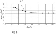
- a characteristic curve can be used to determine the permissible lateral acceleration a quer zul depending on the speed v .
- Figure 5 is a schematic view of the characteristic curve KL2.
- the additional speed limit For the additional speed limit, a subsequent investigation can be carried out to determine its necessity based on the acceleration process.
- the additional speed limit is not required, for example, if the acceleration required to reach the speed limit v zul at the subsequent curvature maximum exceeds a specified or specifiable, adjustable acceleration limit (i.e. the additional speed limit differs too much from the following maximum and is therefore obsolete).
- the acceleration limits a Limit 1 and a Limit 1 can be different or the same.
Landscapes
- Engineering & Computer Science (AREA)
- Automation & Control Theory (AREA)
- Transportation (AREA)
- Mechanical Engineering (AREA)
- Traffic Control Systems (AREA)
- Control Of Driving Devices And Active Controlling Of Vehicle (AREA)
- Complex Calculations (AREA)
Claims (10)
- Procédé pour la limitation d'une vitesse de déplacement (v) d'un véhicule lors du passage d'un virage (K), dans lequel un tracé d'une courbure (κ) d'un tronçon de route précédant le véhicule est déterminé et, en fonction du tracé de la courbure (κ) et de limites de charge physiques du véhicule, un tracé d'une vitesse de virage admissible (v) est déterminé et le véhicule est commandé de telle sorte que les vitesses de virage admissibles (v) déterminées ne sont pas dépassées lors du passage du virage (K), dans lequel- en évaluant le tracé de la courbure (κ), un tronçon de route sur lequel la courbure (κ) est supérieure à une valeur limite de courbure (κlim ) prédéfinie est identifié comme tronçon de virage, caractérisé en ce que- sur le tronçon de virage identifié, des maxima locaux de courbure sont identifiés, et dans lequel- en cas d'identification de plusieurs maxima locaux de courbure sur le tronçon de virage, une vitesse de virage admissible (v) est déterminée pour chaque maximum local de courbure en fonction de la courbure (κ) et d'une accélération transversale admissible (aquer
zul ). - Procédé selon la revendication 1,
caractérisé en ce que l'accélération transversale admissible (aquerzul ) est prédéfinie en fonction de la courbure (κ). - Procédé selon la revendication 2,
caractérisé en ce que l'accélération transversale admissible (aquerzul ) est prédéfinie en fonction de la courbure (κ) sous la forme d'une courbe caractéristique (KL1) ou d'une table de consultation. - Procédé selon l'une des revendications précédentes,
caractérisé en ce que le tronçon de virage identifié est divisé en plusieurs sections de virage adjacentes (KS1 à KSn), dans lequel des limites entre des sections de courbe adjacentes (KS1 à KSn) sont formées par les maxima locaux de courbure. - Procédé selon l'une des revendications précédentes,
caractérisé en ce que des écarts entre les vitesses de virage admissibles (v) sont déterminés au début et à la fin d'une section de virage (KS1 à KSn) respective, dans lequel au moins une autre vitesse de virage admissible (v) est déterminée sur la section de virage (KS1 à KSn) respective par interpolation, sur la base des vitesses de virage admissibles (v) au début et à la fin de la section de courbe (KS1 à KSn) respective, lorsque l'écart déterminé dépasse un seuil de vitesse prédéfini. - Procédé selon la revendication 5,
caractérisé en ce que l'interpolation est réalisée sous la forme d'une interpolation linéaire. - Procédé selon la revendication 5 ou 6,
caractérisé en ce qu'un nombre des autres vitesses de virage admissibles (v) déterminées est choisi d'autant plus grand que l'écart déterminé entre les vitesses de virage admissibles (v) au début et à la fin de la section de virage (KS1 à KSn) respective est grand. - Procédé selon l'une des revendications 5 à 7,
caractérisé en ce qu'une position respective par rapport à l'au moins une autre vitesse de virage admissible (v) est déterminée en établissant la courbure (κ) associée et en déterminant une position exacte de la limitation de vitesse supplémentaire par interpolation linéaire entre deux valeurs de courbure. - Procédé selon la revendication 8,
caractérisé en ce qu'une courbe caractéristique (KL2) ou une table de consultation est utilisée pour la détermination de l'accélération transversale admissible (aquerzul ) en fonction de la vitesse (v). - Procédé selon l'une des revendications 5 à 9,
caractérisé en ce que, pour la limitation de vitesse supplémentaire, un examen ultérieur de sa nécessité est réalisé sur la base du processus d'accélération, dans lequel la limitation de vitesse supplémentaire est supprimée lorsque l'accélération nécessaire pour atteindre la limitation de vitesse à un maximum de courbure consécutif dépasse une limite d'accélération réglable prédéfinie ou pouvant être prédéfinie.
Applications Claiming Priority (2)
| Application Number | Priority Date | Filing Date | Title |
|---|---|---|---|
| DE102021003873.8A DE102021003873A1 (de) | 2021-07-27 | 2021-07-27 | Verfahren zur Begrenzung einer Fahrgeschwindigkeit eines Fahrzeugs beim Durchfahren einer Kurve |
| PCT/EP2022/067043 WO2023006306A1 (fr) | 2021-07-27 | 2022-06-22 | Procédé de limitation de la vitesse d'un véhicule lors du passage d'un virage |
Publications (3)
| Publication Number | Publication Date |
|---|---|
| EP4351945A1 EP4351945A1 (fr) | 2024-04-17 |
| EP4351945C0 EP4351945C0 (fr) | 2024-10-09 |
| EP4351945B1 true EP4351945B1 (fr) | 2024-10-09 |
Family
ID=82270628
Family Applications (1)
| Application Number | Title | Priority Date | Filing Date |
|---|---|---|---|
| EP22734612.9A Active EP4351945B1 (fr) | 2021-07-27 | 2022-06-22 | Procédé de limitation de la vitesse d'un véhicule lors du passage d'un virage |
Country Status (7)
| Country | Link |
|---|---|
| US (1) | US12139138B2 (fr) |
| EP (1) | EP4351945B1 (fr) |
| JP (1) | JP7637314B2 (fr) |
| KR (1) | KR102690153B1 (fr) |
| CN (1) | CN117730024B (fr) |
| DE (1) | DE102021003873A1 (fr) |
| WO (1) | WO2023006306A1 (fr) |
Families Citing this family (2)
| Publication number | Priority date | Publication date | Assignee | Title |
|---|---|---|---|---|
| JP7661389B2 (ja) * | 2023-03-30 | 2025-04-14 | 本田技研工業株式会社 | 車両用制御装置、車両制御方法、およびプログラム |
| CN119190034B (zh) * | 2024-10-31 | 2025-09-30 | 广州海珀特科技有限公司 | 一种提前识别弯道的方法 |
Family Cites Families (31)
| Publication number | Priority date | Publication date | Assignee | Title |
|---|---|---|---|---|
| JPH10269495A (ja) * | 1997-03-26 | 1998-10-09 | Mitsubishi Motors Corp | 車両の走行補助装置 |
| JP3388132B2 (ja) | 1997-04-09 | 2003-03-17 | 本田技研工業株式会社 | 車両制御装置 |
| US6212465B1 (en) | 1999-12-22 | 2001-04-03 | Visteon Global Technologies Inc. | Method and system for controlling vehicle speed based on vehicle yaw rate and yaw acceleration |
| JP3979400B2 (ja) | 2004-04-23 | 2007-09-19 | 日産自動車株式会社 | 前方道路対応制御装置 |
| DE102004040351A1 (de) | 2004-08-20 | 2006-03-09 | Daimlerchrysler Ag | Verfahren zum Klassifizieren von Streckenabschnitten, zugehöriges Verfahren und Vorrichtung zur Getriebesteuerung für ein Fahrzeug |
| JP4654692B2 (ja) * | 2005-01-18 | 2011-03-23 | トヨタ自動車株式会社 | 旋回車速設定装置 |
| DE102006006365A1 (de) | 2006-02-11 | 2007-08-16 | Daimlerchrysler Ag | Verfahren und Vorrichtung zur Längsbewegungssteuerung eines Fahrzeugs |
| JP5257923B2 (ja) * | 2008-01-31 | 2013-08-07 | 株式会社アドヴィックス | 車両の運動制御装置 |
| DE102009000397A1 (de) | 2009-01-23 | 2010-07-29 | Robert Bosch Gmbh | Verfahren zum Auslösen eines automatischen Bremseingriffs vor Kurven |
| DE102009023489A1 (de) | 2009-05-30 | 2010-12-16 | Daimler Ag | Verfahren und Vorrichtung zur Geschwindigkeitsregelung eines Fahrzeugs |
| DE102011006741B4 (de) | 2011-04-04 | 2024-01-18 | Bayerische Motoren Werke Aktiengesellschaft | Vorausschauende Steuerung eines Automatikgetriebes |
| JP5673597B2 (ja) | 2011-11-18 | 2015-02-18 | 株式会社デンソー | 車両用挙動制御装置 |
| KR101338592B1 (ko) * | 2012-06-12 | 2013-12-06 | 기아자동차주식회사 | 스마트 크루즈 컨트롤 시스템의 곡선로 속도 제어 장치 및 방법 |
| JP6161942B2 (ja) | 2013-04-19 | 2017-07-12 | 株式会社デンソーアイティーラボラトリ | カーブ形状モデル化装置、車両情報処理システム、カーブ形状モデル化方法、及びカーブ形状モデル化プログラム |
| KR20150062490A (ko) | 2013-11-29 | 2015-06-08 | 주식회사 만도 | 차량의 차속 제어 장치 및 방법 |
| SE539599C2 (sv) | 2014-05-21 | 2017-10-17 | Scania Cv Ab | Förfarande och system för att anpassa ett fordons acceleration vid framförande av fordonet utmed en färdväg |
| DE102015116877B4 (de) | 2014-10-06 | 2025-03-13 | Hl Klemove Corp. | Geschwindigkeitssteuersystem und geschwindigkeitssteuerverfahren für gekrümmte strassenabschnitte |
| DE102015013143A1 (de) | 2015-10-13 | 2017-04-13 | Knorr-Bremse Systeme für Nutzfahrzeuge GmbH | Verfahren zur vorausschauenden Umkippverhinderung eines Fahrzeugs |
| DE102016216156B3 (de) | 2016-08-29 | 2018-02-22 | Audi Ag | Verfahren und Steuervorrichtung zum Betreiben eines Kraftfahrzeugs |
| AT520320B1 (de) | 2017-09-26 | 2019-03-15 | Avl List Gmbh | Verfahren und eine Vorrichtung zum Erzeugen eines dynamischen Geschwindigkeitsprofils eines Kraftfahrzeugs |
| DE102018210495A1 (de) | 2018-06-27 | 2020-01-02 | Bayerische Motoren Werke Aktiengesellschaft | Verfahren zum Bereitstellen von Radien eines Kurvenabschnitts einer Strecke mittels geometrischer Navigationsdaten einer digitalen Navigationskarte eines Fahrzeugs, computerlesbares Medium, System, und Fahrzeug umfassend das System |
| EP3647143B1 (fr) * | 2018-11-01 | 2023-08-16 | Zenuity AB | Procédé et agencement de réglage de vitesse de courbe continue pour un véhicule routier |
| FR3088882B1 (fr) * | 2018-11-23 | 2020-10-30 | Psa Automobiles Sa | Régulation de la vitesse d’un véhicule en virage en fonction de la consigne de vitesse |
| JP7147524B2 (ja) * | 2018-12-07 | 2022-10-05 | トヨタ自動車株式会社 | 車両制御装置 |
| DE102018222227A1 (de) | 2018-12-19 | 2020-06-25 | Zf Friedrichshafen Ag | Verfahren zum Anpassen einer Fahrzeuggeschwindigkeit |
| DE102019200541A1 (de) | 2019-01-17 | 2020-07-23 | Ford Global Technologies, Llc | Verfahren zur adaptiven Geschwindigkeitsregelung eines Fahrzeugs, System zur Datenverarbeitung, Computerprogrammprodukt und computerlesbarer Datenträger |
| EP3747718B1 (fr) * | 2019-06-04 | 2021-11-03 | Zenuity AB | Procédé d'adaptation de réglages de paramètres de mise au point d'une fonctionnalité système de commande du réglage de la vitesse d'un véhicule routier |
| CN110155059B (zh) * | 2019-06-04 | 2020-08-07 | 吉林大学 | 一种弯道优化控制方法及系统 |
| KR102712068B1 (ko) * | 2019-08-16 | 2024-10-02 | 현대자동차주식회사 | 가속도 프로파일 생성 장치 및 이를 이용한 곡선 도로의 자율주행 방법 |
| CN110667576B (zh) * | 2019-10-18 | 2021-04-20 | 北京百度网讯科技有限公司 | 自动驾驶车辆的弯道通行控制方法、装置、设备和介质 |
| IT202000002746A1 (it) * | 2020-02-12 | 2021-08-12 | Ferrari Spa | Metodo di controllo durante la percorrenza di una curva di un veicolo stradale con rigidezza variabile e ruote posteriori sterzanti |
-
2021
- 2021-07-27 DE DE102021003873.8A patent/DE102021003873A1/de active Pending
-
2022
- 2022-06-22 US US18/292,394 patent/US12139138B2/en active Active
- 2022-06-22 JP JP2024504923A patent/JP7637314B2/ja active Active
- 2022-06-22 EP EP22734612.9A patent/EP4351945B1/fr active Active
- 2022-06-22 CN CN202280052007.0A patent/CN117730024B/zh active Active
- 2022-06-22 WO PCT/EP2022/067043 patent/WO2023006306A1/fr not_active Ceased
- 2022-06-22 KR KR1020247002519A patent/KR102690153B1/ko active Active
Also Published As
| Publication number | Publication date |
|---|---|
| KR102690153B1 (ko) | 2024-07-30 |
| WO2023006306A1 (fr) | 2023-02-02 |
| US20240278779A1 (en) | 2024-08-22 |
| DE102021003873A1 (de) | 2023-02-02 |
| EP4351945C0 (fr) | 2024-10-09 |
| US12139138B2 (en) | 2024-11-12 |
| JP7637314B2 (ja) | 2025-02-27 |
| EP4351945A1 (fr) | 2024-04-17 |
| KR20240027020A (ko) | 2024-02-29 |
| JP2024527958A (ja) | 2024-07-26 |
| CN117730024B (zh) | 2024-08-13 |
| CN117730024A (zh) | 2024-03-19 |
Similar Documents
| Publication | Publication Date | Title |
|---|---|---|
| EP4351945B1 (fr) | Procédé de limitation de la vitesse d'un véhicule lors du passage d'un virage | |
| EP3431355B1 (fr) | Procédé de détection et de caractérisation d'un comportement routier d'un conducteur ou d'un pilote automatique dans un véhicule automobile, unité de commande et véhicule automobile | |
| DE112017000401B4 (de) | Spurwechsel-Unterstützvorrichtung und Spurwechsel-Unterstützverfahren | |
| EP4298001B1 (fr) | Procédé et système d'aide à la conduite pour assister un véhicule automobile lors d'une prise de virage | |
| EP3279050B1 (fr) | Système de commande et procédé de commande destiné à sélectionner et à suivre un véhicule automobile | |
| WO2018068917A1 (fr) | Catégorisation de véhicules dans l'environnement d'un véhicule automobile | |
| DE102016109852A1 (de) | Verfahren zum Manövrieren eines Kraftfahrzeugs in eine Parklücke mit Bestimmung einer Einparktrajektorie, Fahrerassistenzsystem sowie Kraftfahrzeug | |
| DE102010062129B4 (de) | Verfahren und Vorrichtung zum Bereitstellen einer virtuellen Begrenzung eines Fahrstreifens | |
| DE19932200A1 (de) | Fahrzeug-Fahrsteuerungs-/Regelungseinrichtung | |
| DE102009021019B4 (de) | Verfahren zum Generieren einer Fahrstrategie | |
| DE102012011301A1 (de) | Die Erfindung bezieht sich auf ein Verfahren zur Steuerung eines Spurhalteassistenten für ein Kraftfahrzeug | |
| DE19502954B4 (de) | Verfahren zur Geschwindigkeitsregelung eines Kraftfahrzeuges | |
| EP3279051B1 (fr) | Système de commande et procédé de commande destiné à sélectionner et à suivre un véhicule automobile | |
| DE102017220486A1 (de) | Verfahren zur Adaption einer vorbestimmten Referenzlinie für ein Kraftfahrzeug und Vorrichtung | |
| DE102022116267A1 (de) | Verfahren zum Betreiben eines Spurwechselassistenzsystems eines Fahrzeugs mit Berücksichtigung einer Verkehrsdichte in einer Umgebung des Fahrzeugs, Spurwechselassistenzsystem sowie Fahrzeug | |
| DE102025102707A1 (de) | Fahrzeug, steuergerät und verfahren zur vorausschauenden wahl eines gangs eines automatikgetriebes des fahrzeugs | |
| DE102023211070B4 (de) | Verfahren zur Längsführung eines Fahrzeugs in Bezug zu einem vorausfahrenden Vorderfahrzeug mittels eines elektronischen Abstandshaltesystems sowie ein Abstandshaltesystem für ein Fahrzeug | |
| EP2319730B1 (fr) | Procédé de fonctionnement d'un système d'éclairage adaptatif prédictif dans un véhicule automobile et véhicule automobile | |
| DE102022203133A1 (de) | Verfahren zum Manövrieren eines Fahrzeugs in eine Parklücke | |
| EP0813986A2 (fr) | Méthode de commande de distance d'un véhicule | |
| DE112020001547T5 (de) | Fahrunterstützungsvorrichtung für ein Fahrzeug | |
| EP4251488A1 (fr) | Optimisation d'un système d'assistance au guidage latéral | |
| EP4341141B1 (fr) | Système d'aide à la conduite | |
| DE102019125817A1 (de) | Verfahren zur Planung einer oder mehrerer Trajektorien eines Fahrzeugs und System zum Durchführen des Verfahrens | |
| DE102024001929A1 (de) | Verfahren zur Erkennung eines Spurwechsels |
Legal Events
| Date | Code | Title | Description |
|---|---|---|---|
| STAA | Information on the status of an ep patent application or granted ep patent |
Free format text: STATUS: UNKNOWN |
|
| STAA | Information on the status of an ep patent application or granted ep patent |
Free format text: STATUS: THE INTERNATIONAL PUBLICATION HAS BEEN MADE |
|
| PUAI | Public reference made under article 153(3) epc to a published international application that has entered the european phase |
Free format text: ORIGINAL CODE: 0009012 |
|
| STAA | Information on the status of an ep patent application or granted ep patent |
Free format text: STATUS: REQUEST FOR EXAMINATION WAS MADE |
|
| 17P | Request for examination filed |
Effective date: 20240110 |
|
| AK | Designated contracting states |
Kind code of ref document: A1 Designated state(s): AL AT BE BG CH CY CZ DE DK EE ES FI FR GB GR HR HU IE IS IT LI LT LU LV MC MK MT NL NO PL PT RO RS SE SI SK SM TR |
|
| GRAP | Despatch of communication of intention to grant a patent |
Free format text: ORIGINAL CODE: EPIDOSNIGR1 |
|
| STAA | Information on the status of an ep patent application or granted ep patent |
Free format text: STATUS: GRANT OF PATENT IS INTENDED |
|
| DAV | Request for validation of the european patent (deleted) | ||
| DAX | Request for extension of the european patent (deleted) | ||
| INTG | Intention to grant announced |
Effective date: 20240701 |
|
| GRAS | Grant fee paid |
Free format text: ORIGINAL CODE: EPIDOSNIGR3 |
|
| GRAA | (expected) grant |
Free format text: ORIGINAL CODE: 0009210 |
|
| STAA | Information on the status of an ep patent application or granted ep patent |
Free format text: STATUS: THE PATENT HAS BEEN GRANTED |
|
| AK | Designated contracting states |
Kind code of ref document: B1 Designated state(s): AL AT BE BG CH CY CZ DE DK EE ES FI FR GB GR HR HU IE IS IT LI LT LU LV MC MK MT NL NO PL PT RO RS SE SI SK SM TR |
|
| REG | Reference to a national code |
Ref country code: CH Ref legal event code: EP |
|
| REG | Reference to a national code |
Ref country code: DE Ref legal event code: R096 Ref document number: 502022001868 Country of ref document: DE |
|
| REG | Reference to a national code |
Ref country code: IE Ref legal event code: FG4D Free format text: LANGUAGE OF EP DOCUMENT: GERMAN |
|
| U01 | Request for unitary effect filed |
Effective date: 20241031 |
|
| U07 | Unitary effect registered |
Designated state(s): AT BE BG DE DK EE FI FR IT LT LU LV MT NL PT RO SE SI Effective date: 20241112 |
|
| PG25 | Lapsed in a contracting state [announced via postgrant information from national office to epo] |
Ref country code: IS Free format text: LAPSE BECAUSE OF FAILURE TO SUBMIT A TRANSLATION OF THE DESCRIPTION OR TO PAY THE FEE WITHIN THE PRESCRIBED TIME-LIMIT Effective date: 20250209 Ref country code: HR Free format text: LAPSE BECAUSE OF FAILURE TO SUBMIT A TRANSLATION OF THE DESCRIPTION OR TO PAY THE FEE WITHIN THE PRESCRIBED TIME-LIMIT Effective date: 20241009 |
|
| PG25 | Lapsed in a contracting state [announced via postgrant information from national office to epo] |
Ref country code: ES Free format text: LAPSE BECAUSE OF FAILURE TO SUBMIT A TRANSLATION OF THE DESCRIPTION OR TO PAY THE FEE WITHIN THE PRESCRIBED TIME-LIMIT Effective date: 20241009 |
|
| PG25 | Lapsed in a contracting state [announced via postgrant information from national office to epo] |
Ref country code: NO Free format text: LAPSE BECAUSE OF FAILURE TO SUBMIT A TRANSLATION OF THE DESCRIPTION OR TO PAY THE FEE WITHIN THE PRESCRIBED TIME-LIMIT Effective date: 20250109 |
|
| PG25 | Lapsed in a contracting state [announced via postgrant information from national office to epo] |
Ref country code: GR Free format text: LAPSE BECAUSE OF FAILURE TO SUBMIT A TRANSLATION OF THE DESCRIPTION OR TO PAY THE FEE WITHIN THE PRESCRIBED TIME-LIMIT Effective date: 20250110 |
|
| PG25 | Lapsed in a contracting state [announced via postgrant information from national office to epo] |
Ref country code: PL Free format text: LAPSE BECAUSE OF FAILURE TO SUBMIT A TRANSLATION OF THE DESCRIPTION OR TO PAY THE FEE WITHIN THE PRESCRIBED TIME-LIMIT Effective date: 20241009 |
|
| PG25 | Lapsed in a contracting state [announced via postgrant information from national office to epo] |
Ref country code: RS Free format text: LAPSE BECAUSE OF FAILURE TO SUBMIT A TRANSLATION OF THE DESCRIPTION OR TO PAY THE FEE WITHIN THE PRESCRIBED TIME-LIMIT Effective date: 20250109 |
|
| PG25 | Lapsed in a contracting state [announced via postgrant information from national office to epo] |
Ref country code: SM Free format text: LAPSE BECAUSE OF FAILURE TO SUBMIT A TRANSLATION OF THE DESCRIPTION OR TO PAY THE FEE WITHIN THE PRESCRIBED TIME-LIMIT Effective date: 20241009 |
|
| PG25 | Lapsed in a contracting state [announced via postgrant information from national office to epo] |
Ref country code: SK Free format text: LAPSE BECAUSE OF FAILURE TO SUBMIT A TRANSLATION OF THE DESCRIPTION OR TO PAY THE FEE WITHIN THE PRESCRIBED TIME-LIMIT Effective date: 20241009 |
|
| PG25 | Lapsed in a contracting state [announced via postgrant information from national office to epo] |
Ref country code: CZ Free format text: LAPSE BECAUSE OF FAILURE TO SUBMIT A TRANSLATION OF THE DESCRIPTION OR TO PAY THE FEE WITHIN THE PRESCRIBED TIME-LIMIT Effective date: 20241009 |
|
| U20 | Renewal fee for the european patent with unitary effect paid |
Year of fee payment: 4 Effective date: 20250624 |
|
| PLBE | No opposition filed within time limit |
Free format text: ORIGINAL CODE: 0009261 |
|
| STAA | Information on the status of an ep patent application or granted ep patent |
Free format text: STATUS: NO OPPOSITION FILED WITHIN TIME LIMIT |
|
| 26N | No opposition filed |
Effective date: 20250710 |
|
| REG | Reference to a national code |
Ref country code: CH Ref legal event code: H13 Free format text: ST27 STATUS EVENT CODE: U-0-0-H10-H13 (AS PROVIDED BY THE NATIONAL OFFICE) Effective date: 20260127 |
|
| PG25 | Lapsed in a contracting state [announced via postgrant information from national office to epo] |
Ref country code: MC Free format text: LAPSE BECAUSE OF FAILURE TO SUBMIT A TRANSLATION OF THE DESCRIPTION OR TO PAY THE FEE WITHIN THE PRESCRIBED TIME-LIMIT Effective date: 20241009 |
|
| PG25 | Lapsed in a contracting state [announced via postgrant information from national office to epo] |
Ref country code: IE Free format text: LAPSE BECAUSE OF NON-PAYMENT OF DUE FEES Effective date: 20250622 |
|
| PG25 | Lapsed in a contracting state [announced via postgrant information from national office to epo] |
Ref country code: CH Free format text: LAPSE BECAUSE OF NON-PAYMENT OF DUE FEES Effective date: 20250630 |