EP4352854B1 - Procédé de transfert d'énergie par induction - Google Patents
Procédé de transfert d'énergie par induction Download PDFInfo
- Publication number
- EP4352854B1 EP4352854B1 EP22734873.7A EP22734873A EP4352854B1 EP 4352854 B1 EP4352854 B1 EP 4352854B1 EP 22734873 A EP22734873 A EP 22734873A EP 4352854 B1 EP4352854 B1 EP 4352854B1
- Authority
- EP
- European Patent Office
- Prior art keywords
- primary
- transmitting coil
- current
- voltage
- coil
- Prior art date
- Legal status (The legal status is an assumption and is not a legal conclusion. Google has not performed a legal analysis and makes no representation as to the accuracy of the status listed.)
- Active
Links
Images


Classifications
-
- H—ELECTRICITY
- H02—GENERATION; CONVERSION OR DISTRIBUTION OF ELECTRIC POWER
- H02J—ELECTRIC POWER NETWORKS; CIRCUIT ARRANGEMENTS OR SYSTEMS FOR SUPPLYING OR DISTRIBUTING ELECTRIC POWER; SYSTEMS FOR STORING ELECTRIC ENERGY
- H02J50/00—Circuit arrangements or systems for wireless supply or distribution of electric power
- H02J50/10—Circuit arrangements or systems for wireless supply or distribution of electric power using inductive coupling
- H02J50/12—Circuit arrangements or systems for wireless supply or distribution of electric power using inductive coupling of the resonant type
-
- B—PERFORMING OPERATIONS; TRANSPORTING
- B60—VEHICLES IN GENERAL
- B60L—PROPULSION OF ELECTRICALLY-PROPELLED VEHICLES; SUPPLYING ELECTRIC POWER FOR AUXILIARY EQUIPMENT OF ELECTRICALLY-PROPELLED VEHICLES; ELECTRODYNAMIC BRAKE SYSTEMS FOR VEHICLES IN GENERAL; MAGNETIC SUSPENSION OR LEVITATION FOR VEHICLES; MONITORING OPERATING VARIABLES OF ELECTRICALLY-PROPELLED VEHICLES; ELECTRIC SAFETY DEVICES FOR ELECTRICALLY-PROPELLED VEHICLES
- B60L53/00—Methods of charging batteries, specially adapted for electric vehicles; Charging stations or on-board charging equipment therefor; Exchange of energy storage elements in electric vehicles
- B60L53/60—Monitoring or controlling charging stations
- B60L53/66—Data transfer between charging stations and vehicles
-
- H—ELECTRICITY
- H01—ELECTRIC ELEMENTS
- H01F—MAGNETS; INDUCTANCES; TRANSFORMERS; SELECTION OF MATERIALS FOR THEIR MAGNETIC PROPERTIES
- H01F38/00—Adaptations of transformers or inductances for specific applications or functions
- H01F38/14—Inductive couplings
-
- H—ELECTRICITY
- H02—GENERATION; CONVERSION OR DISTRIBUTION OF ELECTRIC POWER
- H02J—ELECTRIC POWER NETWORKS; CIRCUIT ARRANGEMENTS OR SYSTEMS FOR SUPPLYING OR DISTRIBUTING ELECTRIC POWER; SYSTEMS FOR STORING ELECTRIC ENERGY
- H02J50/00—Circuit arrangements or systems for wireless supply or distribution of electric power
- H02J50/80—Circuit arrangements or systems for wireless supply or distribution of electric power involving the exchange of data, concerning supply or distribution of electric power, between transmitting devices and receiving devices
-
- B—PERFORMING OPERATIONS; TRANSPORTING
- B60—VEHICLES IN GENERAL
- B60L—PROPULSION OF ELECTRICALLY-PROPELLED VEHICLES; SUPPLYING ELECTRIC POWER FOR AUXILIARY EQUIPMENT OF ELECTRICALLY-PROPELLED VEHICLES; ELECTRODYNAMIC BRAKE SYSTEMS FOR VEHICLES IN GENERAL; MAGNETIC SUSPENSION OR LEVITATION FOR VEHICLES; MONITORING OPERATING VARIABLES OF ELECTRICALLY-PROPELLED VEHICLES; ELECTRIC SAFETY DEVICES FOR ELECTRICALLY-PROPELLED VEHICLES
- B60L53/00—Methods of charging batteries, specially adapted for electric vehicles; Charging stations or on-board charging equipment therefor; Exchange of energy storage elements in electric vehicles
- B60L53/10—Methods of charging batteries, specially adapted for electric vehicles; Charging stations or on-board charging equipment therefor; Exchange of energy storage elements in electric vehicles characterised by the energy transfer between the charging station and the vehicle
- B60L53/12—Inductive energy transfer
- B60L53/122—Circuits or methods for driving the primary coil, e.g. supplying electric power to the coil
-
- H—ELECTRICITY
- H02—GENERATION; CONVERSION OR DISTRIBUTION OF ELECTRIC POWER
- H02K—DYNAMO-ELECTRIC MACHINES
- H02K11/00—Structural association of dynamo-electric machines with electric components or with devices for shielding, monitoring or protection
- H02K11/0094—Structural association with other electrical or electronic devices
-
- H—ELECTRICITY
- H02—GENERATION; CONVERSION OR DISTRIBUTION OF ELECTRIC POWER
- H02K—DYNAMO-ELECTRIC MACHINES
- H02K41/00—Propulsion systems in which a rigid body is moved along a path due to dynamo-electric interaction between the body and a magnetic field travelling along the path
- H02K41/02—Linear motors; Sectional motors
- H02K41/03—Synchronous motors; Motors moving step by step; Reluctance motors
- H02K41/031—Synchronous motors; Motors moving step by step; Reluctance motors of the permanent magnet type
Definitions
- the present invention relates to a method for inductive energy transmission between a primary part and a secondary part, wherein the primary part and the secondary part are parts of a transport system, preferably a linear motor system, a planar motor system or a magnetic levitation train, wherein the primary part corresponds to a fixed part of the transport system and the secondary part to a part of the transport system that is movable relative to this part, wherein the secondary part is moved relative to the primary part, wherein an electrical primary current is introduced from a supply unit into a transmitting coil arranged on the primary part to build up a first alternating magnetic field for energy transmission, whereby an electrical alternating voltage is induced in a receiving coil arranged on the secondary part, which brings about an electrical secondary current at the secondary part and thus a power flow comprising uncompensated active power to at least one consumer connected to the receiving coil.
- a transport system preferably a linear motor system, a planar motor system or a magnetic levitation train
- the primary part corresponds to a fixed part of
- Feed-in and transmission limitations often arise from the physical limitations of power electronic devices, particularly when these are located in supply units for the electrical supply of energy transmission systems.
- Examples of physical limitations in this regard include limited DC link voltages and thus limited supply voltages, limited electrical currents due to often limited thermal load capacity, and electromagnetic effects such as the skin or proximity effect.
- a direct consequence of a limited supply voltage in combination with a limited permissible current is a limitation of the available electrical (supply) power, which can severely impair the delivery of electrical energy from a supply unit to a power supply system.
- resonant coupling In the case of inductive energy transfer, capacitive energy storage devices in the form of capacitors are connected to the commonly provided transmitting and receiving coils. Connecting the transmitting and receiving coils with capacitors creates resonant circuits, while the combination of the resonant circuits results in a resonant electrical circuit.
- the usual goal of resonant coupling at this point is to select the frequency of the supply voltage applied to the transmitting coil, often referred to as the excitation frequency, as close as possible to a resonant frequency of the resonant electrical circuit. This primarily increases the magnetic coupling between the transmitting and receiving coils, which can often result in efficient and low-loss energy transfer.
- resonant coupling is often significantly complicated, particularly due to the fact that relative movements between the components involved in energy transfer during operation are not only possible, but are usually the norm. Such relative movements often significantly influence the resonance frequencies of an energy transfer system. Due to the fact that resonant coupling typically requires precise and highly accurate matching between the excitation frequency and the resonance frequency, shifts in resonance frequencies can in many cases have a very negative impact on the amount of energy ultimately transferred.
- stationary components of a transport system are often referred to as “primary parts,” whereas components of a transport system that are movable relative to a primary part are usually referred to as “secondary parts.”
- secondary parts Particularly in linear motor technology, electrical and/or electronic components are increasingly arranged on the movable secondary parts, for which an appropriate electrical power supply must be provided. Since, on the one hand, batteries on and in the secondary parts are often not desired, and on the other hand, conductive energy transmission for supply is often not feasible, the question of contactless energy transmission, which should be low-loss and efficient, is particularly important for linear and planar motor systems, despite the difficult conditions caused by possible Relative movements between the primary and secondary parts are of great importance. This fact is also reflected in the current state of the art.
- the EP 2793356 B1 and the EP 2903407 A1 disclose a capacitive energy transfer from a static primary part to a relatively movable secondary part, for which both the primary and secondary parts are equipped with electrode plates.
- the electrode plates serve to create an electric field between the primary and secondary parts, through which the desired energy transfer takes place.
- Similar to the US 7958830 B2 describes the EP 2793356 B1 a tuning of the electrical components involved in the energy transfer to achieve a minimum impedance of the electrical circuit formed by the electrical components involved, although here, too, no details are given on how this adjustment is carried out.
- US 2012/217111 A1 also shows a system for supplying power to electric vehicles on the road, in which several modules arranged in or under a roadway are provided to provide inductive power to electric vehicles.
- the components of the US 2012/217111 A1 However, they must stand still.
- a further disadvantage of known methods for both capacitive and inductive energy transmission in transport systems arises, as mentioned, from the fact that relative movements usually occur between a supplying primary part and a supplied secondary part. This can lead to changes in the transmission and coupling conditions between the components of an energy transmission system. change, which can, among other things, result in a shift in the electrical resonance frequencies of the energy transmission system. If the contactless energy transmission in this context is based on resonant coupling, the excitation frequency must, for obvious reasons, be adapted to any changing resonance frequencies. Such adaptation is not disclosed in the prior art. In addition to relative movements between the primary and secondary parts, heating, aging, wear, and nonlinear properties of electrical components can also cause changes in the transmission conditions, which further increases the need for a suitable adaptation mechanism.
- main inductance represents that portion of both coils that generates a magnetic flux passing through both coils, thus having both self- and mutual induction effects and thus bringing about the coupling of primary and secondary parts necessary for inductive energy transfer.
- large stray inductances are disadvantageous for several reasons. In particular, they increase the reactive power that occurs, which Especially when the supply voltage or supply power is only available to a limited extent, the transferable active power is directly reduced.
- a transmitting coil is to simultaneously transmit energy and generate propulsive force, this is usually achieved by superimposing low-frequency currents, which are introduced into the drive coils to generate propulsive force and are therefore also referred to as drive currents, with higher-frequency currents, which in turn bring about the desired energy transfer. If, in such a case, the available supply voltage is limited and a large portion of this limited supply voltage is already used to generate currents for force generation, it is clear that the remaining voltage reserve must be optimally utilized to transmit active power.
- the system is based on a system for inductive energy transmission between a primary and a secondary part, wherein the primary part and the secondary part are parts of a transport system, preferably a linear motor system, a planar motor system, or a magnetic levitation train, wherein the primary part corresponds to a stationary part of the transport system and the secondary part to a part of the transport system that is movable relative to the primary part.
- a transport system preferably a linear motor system, a planar motor system, or a magnetic levitation train
- the secondary part is moved relative to the primary part by introducing an electrical primary current into a transmitting coil arranged on the primary part by means of a supply unit, which primary current creates a first alternating magnetic field for energy transmission, which induces an electrical alternating voltage in a receiving coil arranged on the secondary part and thereby creates a current and thus a first power flow to at least one consumer connected to the receiving coil.
- first power flow it applies that this would also occur without application of the method according to the invention described below, but would only transport a so-called nominal active power.
- Such nominal active power is also referred to below as "uncompensated" active power.
- the present invention provides for such a system, by means of a compensation unit arranged on the secondary part, which is moved relative to the primary part, a secondary-side compensation current into the secondary-side receiving coil or, if necessary, into another coil arranged on the secondary part.
- the purpose of the secondary-side introduction of compensation current is to generate a second alternating magnetic field, which induces a compensation voltage in the transmitting coil on the primary part, which changes the phase shift between the total voltage drop across the transmitting coil and the current flowing through the transmitting coil.
- the change in this phase shift takes place in such a way that the active power transferred from the primary to the secondary part during the energy transfer is increased. This procedure takes into account the fact that the active power transferred to a consumer located on the secondary side is of particular importance for supplying this consumer.
- no element which changes the phase shift between the electrical primary voltage dropping across the transmitting coil and the primary current flowing through the transmitting coil is incorporated into the transmitting coil arranged on the primary part.
- a primary-side compensation current is introduced, which is provided by an electrical storage element connected in series with the transmitting coil and between the supply unit and the transmitting coil. Capacitors are preferred as electrical storage elements for providing a compensation current. However, a capacitor connected in series with the transmitting coil would prevent the introduction of a direct current into the transmitting coil. For this reason, the omission of storage elements connected in series with the transmitting coil also allows DC electrical quantities, such as a direct electrical current, to be set in the transmitting coil.
- the phase shift between the primary voltage drop across the transmitting coil and the primary current flowing through the transmitting coil is changed only, i.e., exclusively, by the primary-side compensation voltage caused by the secondary-side compensation current and induced in the transmitting coil.
- electrical storage elements for providing a compensation current are completely dispensed with on the primary side, which includes the dispensing with storage elements connected both in series and in parallel with the transmitting coil.
- the ability to supply a transmitting coil with direct current via the supply unit is particularly crucial when using the energy transmission system in transport systems, such as linear motor systems, planar motor systems, or magnetic levitation trains.
- transmitting coils are often also used to generate a driving force, which in many cases also requires direct currents to be introduced into the transmitting coils.
- additional storage elements provided on the primary part for providing a primary-side compensation current are completely dispensed with.
- no storage elements connected in series or parallel to the transmitting coil such as capacitors or other storage elements, are provided.
- storage elements connected in parallel to the transmitting coil would not fundamentally preclude the use of the energy transmission system in question in one of the aforementioned transport systems, in many cases the use of storage elements connected in parallel to transmitting coils is associated with considerable effort, particularly since linear motor systems have a large number of transmitting coils, so that in such a case a large total number of storage elements would have to be provided.
- Reactive power transmitted during inductive energy transmission is known to oscillate back and forth between electrical storage elements and therefore does not make a lasting contribution to the supply of secondary consumers.
- the present invention takes this circumstance into account and therefore, as described the focus on the transmitted active power. It has been shown that the phase position between the voltage drop across the transmitting coil and the current flowing through the transmitting coil is particularly important for increasing the transmitted active power. Maximum transmitted active power is achieved when the aforementioned phase position is either zero or plus/minus 180 degrees. By introducing a secondary-side compensation current, this very phase position is modified in such a way that the transmitted active power is increased compared to operation without the introduction of compensation current.
- the (paradoxical) case can even occur that the total apparent power transmitted is lower compared to operation of an inductive energy transmission system without the introduction of compensation current according to the invention.
- Resonant coupling is not explicitly sought and, in particular, does not represent a necessary prerequisite for the use of the method according to the invention.
- the secondary side supports the primary side with an additional voltage induced in the main inductance of the energy transmission system during the recharging of the main inductance.
- the power introduced with the secondary-side compensation current itself represents a mostly capacitive reactive power.
- this mostly capacitive reactive power is deliberately transferred from the secondary side to the primary side.
- this often results in the reactive power occurring in the main inductance and often also in the primary-side stray inductances no longer having to be provided exclusively by the supply unit.
- the advantageous side effect of at least partial secondary-side compensation of primary-side reactive power can often contribute to a further improvement in energy transmission.
- At least 50% of the reactive power of the main inductance is provided on the secondary side, i.e., by the secondary part.
- at least 75% of the reactive power of the main inductance can also be provided by the secondary part, or at least 90% of the reactive power of the main inductance can be provided by the Secondary part.
- the entire reactive power of the main inductance is provided by the secondary part.
- less than 20% of the reactive power of the primary-side stray inductances is always provided on the secondary side, i.e., by the secondary part.
- less than 15% of the reactive power of the primary-side stray inductances can also be provided by the secondary part, or less than 10% of the reactive power of the primary-side stray inductances can also be provided by the secondary part.
- a significantly larger portion of the reactive power of the main inductance is typically compensated than by the reactive power of the primary-side stray inductances.
- primary-side reactive power compensation can also be dispensed with if the secondary part does not fully compensate the reactive power of the main inductance, e.g., if complete compensation of the reactive power of the main inductance is not desired.
- this makes it possible to dispense with components for reactive power compensation on the primary part, such as capacitors connected in parallel or series with the primary-side transmitting coil.
- a secondary-side compensation unit which supplies a secondary-side compensation current to a receiving coil provided on the secondary part or receives it from this.
- a compensation unit can be implemented in various ways, for example in the form of a controllable alternating current source, which itself is supplied with previously inductively transmitted energy, or by capacitors with at least partially variable capacitance.
- combinations of different approaches for introducing a secondary-side compensation current are also conceivable, in particular in order to combine the advantages of several different technologies.
- the compensation unit is only provided on the secondary part according to the invention, a precise modification, in particular of the phase relationships between primary-side variables, is nevertheless possible.
- a compensation unit located solely on the secondary part represents a significant advantage, particularly in the implementation of efficient energy transfer in long-stator linear motors.
- Such drive systems are typically characterized by a large number of drive coils located on the primary part. In practice, these drive coils are often used simultaneously as transmitting coils for inductive energy transfer to generate a propulsive force. This is usually achieved by superimposing electrical currents to generate a propulsive force with higher-frequency currents for energy transfer.
- a further advantage of the inventive concept is its improved adaptability to changing transmission ratios compared to many conventional concepts, for example due to relative movements between the primary and secondary parts.
- This advantage arises, on the one hand, from the fact that only the secondary-side compensation current needs to be adjusted for adaptation, for example by varying the frequency and/or phase position and/or amplitude of the compensation current output by the compensation unit.
- the need to optimize components on a large and extensive primary part can lead to difficulties in practical implementation.
- practical use has shown that the modification of a phase shift between two electrical variables of a primary part can be carried out much more robustly than a highly sensitive tuning of an excitation frequency to a possibly rapidly changing resonance frequency.
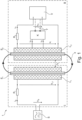
- Fig. 1 shows the basic structure of an inductive energy transmission system 1.
- An electrical alternating voltage u S is delivered from a supply unit S to the part of the energy transmission system 1 located on the primary part I.
- the alternating voltage u S is typically limited in magnitude, particularly in accordance with the initial statements regarding the physical limits of the power electronics used for supply, and therefore cannot be increased arbitrarily during energy transmission.
- the frequency of the supply voltage u S is also referred to below as the "excitation frequency.”
- the supply voltage u S subsequently causes a primary current i S in the form of an alternating electrical current through the primary-side ohmic resistance R 1 , which represents all ohmic resistances concentrated on the primary part I, and the primary-side transmitting coil L 1 .
- the ohmic resistance R 1 is in the Fig.1 shown embodiment is connected between the transmitting coil L 1 and the supply unit S, so that the ohmic resistor R 1 and the transmitting coil L 1 form a series circuit.
- the excitation frequency of the supply voltage u S determines the frequency of the primary current i S.
- the frequency of the primary current i S thus corresponds to the frequency of the supply voltage u S , which corresponds to the excitation frequency.
- the primary-side ohmic resistor R 1 is provided between the supply unit S and the transmitting coil L 1.
- the primary-side ohmic resistor R 1 is arranged in series with the transmitting coil L 1. Otherwise, no further electrical storage elements, such as capacitors, etc., are provided on the primary part I between the transmitting coil L 1 and the supply unit S, and thus in particular no further electrical storage elements which, like the ohmic resistor R 1 , are connected in series with the transmitting coil L 1. Since only the ohmic resistor R 1 is connected between the supply unit S and the transmitting coil L 1 , it is possible to also introduce direct currents into the transmitting coil L 1 , which is of crucial importance, particularly for applications in transport systems.
- an iron core E 1 can optionally be incorporated into the transmitting coil L 1.
- Possible embodiments of an iron core E 1 can be provided, among other things, by ferrites, powder cores or even by laminated structures, where Instead of the term iron core, the term "magnetic core" is also commonly used. The same can be provided for the receiving coil L 2 on the secondary part II by the iron core E 2 .
- the primary current i S leads to the formation of a first alternating magnetic field for energy transfer.
- This first alternating magnetic field contributes to the formation of a time-varying magnetic flux ⁇ , which flows through the transmitting coil L 1 and the receiving coil L 2.
- the two coils L 1 and L 2 are separated by the air gap ⁇ L.
- N 2 represents the number of turns of the receiving coil L 2.
- the current i V flows further via the resistor R 2 , which, like the resistor R 1, cumulatively represents the ohmic resistances of the secondary part, to at least one consumer V, across which the voltage u V drops.
- the at least one consumer V can represent a variety of electronic devices, for example a communication, measuring or control unit, or also an accumulator or energy storage device that is charged with the transmitted energy.
- the inventive introduction of a secondary-side compensation current i K is carried out in the case shown by the compensation unit K.
- the secondary-side compensation current i K subsequently causes a second alternating magnetic field for active power optimization, which is superimposed on the first alternating magnetic field for energy transfer and thus brings about a resulting, overall alternating magnetic field.
- the second alternating magnetic field for active power optimization induces an additional alternating voltage in the transmitting coil L 1 , hereinafter referred to as the "primary-side compensation voltage" u K .
- the primary-side compensation voltage u K induced in the transmitting coil L 1 therefore represents a further component of the overall primary voltage u L 1 dropped across the transmitting coil L 1 and thus influences the phase shift between the primary voltage u L 1 dropped across the transmitting coil L 1 and the primary current i S flowing through the transmitting coil L 1 . According to the invention, this phase shift is modified so that the resulting transmitted active power is increased.
- the term "nominal or uncompensated active power P N" is first introduced.
- the uncompensated active power P N describes the active power that would be achieved during conventional, state-of-the-art operation of an inductive energy transmission system without introducing the compensation current i K according to the invention. Nominal or uncompensated active power P N For this reason, it is also referred to as active power without compensation or active power without a changed phase shift.
- the transmitted active power is increased to a new active power, subsequently referred to as the resulting output active power P R.
- the resulting output active power P R represents an increase in the originally transmitted, uncompensated active power P N by at least 10% to 100%, preferably by 100% to 500%, and particularly preferably by 500% to 5000% or more.
- Fig. 1 A connecting line Y from the consumer V to the compensation unit K is shown in dashed form, which, if necessary, enables an electrical supply to the compensation unit K.
- the compensation unit K it is also possible for the compensation unit K to simultaneously extract transmitted energy and function as a rectifier G.
- the consumers V can also be connected directly to the compensation unit K. This can occur, for example, if the compensation unit K contains a controllable alternating current source that can also function as a rectifier G.
- a compensation current i K that is suitable in terms of phase, amplitude, and frequency can be delivered to the secondary-side part of the circuit of the energy transmission system 1.
- More complex implementation variants can be provided by controllable alternating current sources.
- Less complex implementations, on the other hand, are possible, for example, by capacitive storage elements connected in parallel to the receiving coil L 2 , whose capacitance is adjusted during operation in order to always absorb or deliver a desired secondary-side compensation current i K .
- Fig. 2 Two implementation variants in this regard are Fig. 2 shown, where Fig. 2a shows a connection of three capacitors C using two switches T 1 and T 2 . Depending on the switch position, different capacitive resistances result.
- Mechanically variable capacitors such as trimmer or variable capacitors, which can be based on a variety of materials for dielectrics and electrode plates, and electrically variable capacitors, such as capacitance diodes, are just a few examples.
- a preferred embodiment of a variable capacitance is conventional capacitors, such as electrostatic fixed capacitors, where an additive capacitive current is fed in, thus varying their capacitance.
- This implementation variant is in Fig.
- variable inductive storage elements are also conceivable for implementing a compensation unit K. Examples of this include coils in which the positioning of an iron core is changed, or in which, analogous to the introduction of an additive capacitive current in capacitors, an additive voltage is applied to change the inductance.
- a compensation unit K it may prove particularly advantageous to connect capacitors and coils in parallel or series in a compensation unit K.
- Possible implementations of a compensation unit K further include, in particular, microprocessor-based hardware, microcontrollers, and integrated circuits (ASICs, FPGAs, etc.), primarily to enable the determination and ultimately correct introduction of a suitable compensation current i K , for example, by controlling a controllable AC power source.
- ASICs integrated circuits
- FPGAs field-programmable gate array
- analog circuits for example based on analog operational amplifier circuits, can also be mentioned as components of the compensation unit K for this purpose.
- the introduction of the compensation current i K directly into the receiving coil L 2 represents a preferred embodiment of the present invention, but it is also possible to introduce the compensation current i K into another coil provided specifically for this purpose on the secondary part II and to generate the second alternating magnetic field according to the invention using this additional coil.
- FIG. 3 A possible concrete design of a consumer V is shown in Fig. 3 shown.
- the rectifier G converts the transmitted alternating quantities u V and i V into direct quantities u G and i G , which can ultimately supply one or more electrical loads RL provided on the secondary part II.
- a voltage regulator is also connected upstream of a load V.
- Fig. 4 For clarification, a further abstraction step was carried out and the Fig. 1
- the structure shown is shown in a highly simplified manner.
- the supply unit S and the compensation unit K are shown as current sources, although voltage sources could also be used for both elements.
- the current i S impressed by the supply unit does not change or only slightly changes. Consideration of influences that usually occur in reality, such as parasitic elements, leakage currents, non-sinusoidal Input voltages, etc., are omitted for the sake of the simplest possible explanation. However, the following explanations can easily be expanded to include such influences and are therefore not to be understood as restrictive.
- the transmitting coil L 1 and the receiving coil L 2 have the same number of turns, meaning that no transformation ratio needs to be taken into account.
- a generalization of the following explanations to a transformation ratio is trivial for a person skilled in the art.
- the voltage u K induced by this on the primary side I is shown with its own voltage source in series with the transmitting coil L 1.
- the primary voltage drop across the transmitting coil L 1 is again noted as u L 1 , whereby the primary voltage that would arise without application of the method according to the invention is designated as ⁇ L 1 .
- Î and ⁇ L represent the amplitudes of the two quantities
- the angles ⁇ i and ⁇ u describe their phase positions in degrees
- the expression ⁇ ⁇ u - ⁇ i describes their phase shift to each other.
- u K L 12 d dt i K
- L 12 represents the coupled mutual inductance of transmitting coil L 1 and receiving coil L 2
- a compensation current i K i K t I ⁇ K ⁇ sin 2 ⁇ f ⁇ t + ⁇ 180 ⁇ K with the same frequency f also for the compensation voltage u K
- ⁇ K and the phase shift ⁇ u K depend here on the amplitude Î K and the phase shift ⁇ K according to the relationship between u K and i K given above.
- the core of the control task to be solved by the compensation unit K can therefore be formulated as the determination of the secondary-side compensation current i K whose introduction maximizes the transmitted active power.
- the amplitude and phase position of the secondary-side compensation current i K are preferably adjusted, since the frequency is usually already predetermined by the primary-side voltage u S or the primary-side current i S .
- phase relationship of the primary current i S and the primary voltage u L 1 can be calculated, for example, from measured data of the primary current i S and the primary voltage u L 1 .
- the compensation unit K can be supplied with measurement data of relevant electrical quantities, in particular primary-side quantities u L 1 and/or i S , but also secondary-side quantities such as u i , u V or i V .
- relevant measuring sensors can be provided, preferably on the secondary side II, but also on the primary side I, which transmit their measured values to the compensation unit K.
- the primary-side voltage u S and the primary-side current i S are measured and transmitted wirelessly, for example by means of a radio connection, to the compensation unit K in order to avoid cabling between the primary part I and the secondary part II, in particular when the method according to the invention is implemented in a transport system 2.
- a particularly advantageous implementation of the method according to the invention further results from an indirect determination of the primary-side voltage u S and the primary-side current i S , wherein, for example, the primary-side voltage u S and the primary-side current i S are calculated from measurement data of the induced voltage u i and the secondary-side current i V recorded on the secondary side II using an observer or a filter, whereby neither a radio connection nor cabling between the primary I and the secondary part II is necessary to implement the method according to the invention.
- primary-side electrical quantities such as voltage u S and current i S can be omitted.
- a direct voltage u G can be used, which, as shown in Fig. 3 shown, preferably generated by a rectifier G arranged on the secondary side II, can be used as a measure of the quality of the primary-side phase shift.
- This approach is based on the knowledge that in the case of an increased output active power P R transmitted to the load V and thus to the rectifier G, a higher DC voltage u g is rectified by the rectifier G in many cases.
- a higher DC voltage u g can therefore represent a measure of an increased transmission of active power.
- the Voltage u g does not necessarily have to be measured directly, but can also be determined indirectly by means of filtering or observation.
- the excitation frequency i.e. the frequency of the electrical primary current i S and/or the frequency of the supply voltage u S
- the frequency of the electrical primary current i S can deviate from an electrical resonance frequency of the energy transmission system 1 by at least 1% of the value of the frequency of the electrical primary current i S or by at least 5% of the value of the frequency of the electrical primary current i S or by at least 10% of the value of the frequency of the electrical primary current i S or by at least 50% of the value of the frequency of the electrical primary current i S.
- a maximum of active power transferred from the primary side I to the secondary side II is achieved when the excitation frequency and thus the frequency of the electrical primary current i S deviates by more than 1%, or by more than 3%, or by more than 5% of the value of the frequency of the electrical primary current i S from the lowest non-zero resonant frequency of the energy transmission system 1.
- the energy transmission system 1 is deliberately operated next to its resonant frequencies and thus outside its resonance points.
- the energy transmission system 1 is operated at a frequency that is higher, e.g. by 1% or by 3% or by 5%, than the lowest electrical resonance frequency of the energy transmission system 1.
- the transport system 2 consists of a number of transport segments TSk (k is an index that stands for all existing transport segments TS1, TS2, TS3, ...), of which, for reasons of clarity, only the transport segments TS1 ... TS7 are shown as examples.
- the transport segments TSk form various track sections, for example a straight line, curves with different angles and radii, switches, etc., and can be combined very flexibly to form the transport route of the transport system 2.
- the transport segments TSk thus form a transport route along which the transport units Tn (n is an index that stands for all existing transport units T1, T2, T3, T4, ...) can be moved.
- This modular structure enables a very flexible design of the transport system 2.
- the transport segments TSk are usually attached to a stationary support structure 6 (in Fig. 5 not shown).
- the transport system 2 is designed as a long stator linear motor, wherein the stator segments TSk each form a part of a long stator of a long stator linear motor in a manner known per se. Therefore, a plurality of stationary electrical drive coils 7, 8 forming the stator are arranged in the longitudinal direction in a known manner along the long stator of the transport segments TSk (in Fig. 5 for reasons of clarity only indicated for the transport segments TS1, TS2, TS4, TS5, TS6, TS7), through which a drive current flows and which is connected to the drive magnets 4, 5 on the transport units T1 ... Tn (in Fig.
- the electrical drive current also includes a DC component, i.e., a direct current.
- a planar motor essentially has a stator that forms a transport plane in which one or more transport units can be moved at least two-dimensionally.
- the transport units function as secondary parts II with regard to the method according to the invention.
- the stator is generally constructed from one or more transport segments that take on the role of the primary parts I.
- a driving force acting on the transport unit is generated by a magnetic field of the stator (of the transport segment(s)) and a magnetic field of the transport unit interact.
- Fig. 6 shows a detailed view of two adjacent straight transport segments TSk, TSk+1.
- the transport segments TSk, TSk+1 are arranged on a stationary support structure 6 to form a transport path or themselves form part of the stationary support structure 6.
- a magnetically conductive and elastic material 3 can preferably be attached between the transport segments TSk, TSk+1.
- the drive coils 7 of the long stator linear motor are arranged on the transport segments TSk and TSk+1, respectively.
- the drive magnets 4 are arranged on the transport unit Tn.
- a drive magnet 4 can be designed as an electromagnet (excitation coils) and/or as a permanent magnet.
- the drive coils 7 are preferably arranged on teeth 12 of a ferromagnetic core 13 (for example, an iron laminated core).
- the drive coils 7 can, of course, also be designed without a core.
- guide elements such as rollers, wheels, sliding surfaces, guide magnets, etc. (not shown here for reasons of clarity) can also be provided on the transport unit Tn in order to guide and hold the transport unit Tn along the transport path 20, in particular even when stationary.
- guide elements such as rollers, wheels, sliding surfaces, guide magnets, etc.
- the drive coils 7 are usually arranged on the transport segments TSk, TSk+1 at a regular distance from one another in the longitudinal direction (or direction of movement) x, usually referred to as the slot pitch ⁇ n .
- the transport units Tn take on the role of the secondary parts II with regard to the inventive method for inductive energy transmission, which are analogous to the Fig. 1
- the function of the primary part I is taken over by the extended long stator, where, as mentioned, the drive coils 7 can be used additionally for energy transmission by superimposing a higher frequency current for energy transmission on a low frequency drive current to generate a propulsive force Fv.
- the drive coils 7 can be used additionally for energy transmission by superimposing a higher frequency current for energy transmission on a low frequency drive current to generate a propulsive force Fv.
- drive coils 7 In order not to unnecessarily energize drive coils 7 that are far away from a transport unit Tn and therefore do not contribute to a To ensure energy transmission, usually only drive coils in the immediate vicinity of a transport unit Tn are energized. It should be noted that several adjacent drive coils 7 can also cooperate as transmitting coils L1 for energy transmission.
- the method according to the invention also makes it possible in such cases, despite sometimes considerable primary-side reactive power and other restrictions, such as limited supply voltages u S or limited primary currents i S , to also transmit active power to an extent that nevertheless makes it possible to supply one or more secondary-side consumers sufficiently with electrical energy.
- the aforementioned extension of the method according to the invention by simultaneously adapting the excitation frequency to a resulting electrical resonance frequency of the energy transmission system 1 can represent a valuable extension option in the case of long-stator linear motors and planar motors. Since the transmission ratios change due to movements between the primary part I and the secondary part II can change continuously, a further improvement in energy transfer can be achieved by an additional adjustment between the excitation frequency and a resonance frequency of the energy transfer system 1.
Landscapes
- Engineering & Computer Science (AREA)
- Power Engineering (AREA)
- Computer Networks & Wireless Communication (AREA)
- Transportation (AREA)
- Mechanical Engineering (AREA)
- Physics & Mathematics (AREA)
- Chemical & Material Sciences (AREA)
- Combustion & Propulsion (AREA)
- Electromagnetism (AREA)
- Current-Collector Devices For Electrically Propelled Vehicles (AREA)
- Ac-Ac Conversion (AREA)
- Control Of Linear Motors (AREA)
Claims (9)
- Procédé de transfert d'énergie par induction entre une partie primaire (I) et une partie secondaire (II), la partie primaire (I) et la partie secondaire (II) étant des parties d'un système de transport (2), de préférence d'un système à moteur linéaire, d'un système à moteur planaire ou d'un train à sustentation magnétique, la partie primaire (I) correspondant à une partie fixe du système de transport (2) et la partie secondaire (II) correspondant à une partie du système de transport (2) qui est mobile par rapport à celle-ci, la partie secondaire (II) étant déplacée par rapport à la partie primaire (I), un courant électrique primaire (iS ) étant introduit par une unité d'alimentation (S) dans une bobine émettrice (L 1) disposée sur la partie primaire (I) pour créer un premier champ magnétique alternatif destiné au transfert d'énergie, ce qui induit une tension électrique alternative (ui ) dans une bobine réceptrice (L 2) disposée sur la partie secondaire (II), laquelle produit un courant électrique secondaire (iV ) sur la partie secondaire (II) et ainsi un flux de puissance comprenant une puissance active non compensée (PN ) vers au moins une charge (V) connectée à la bobine réceptrice (L 2), caractérisé en ce qu'un courant de compensation côté secondaire (iK ) est introduit dans une bobine côté secondaire (Lk ) par une unité de compensation (K) disposée sur la partie secondaire (II) déplacée par rapport à la partie primaire (I), en ce qu'un deuxième champ magnétique alternatif, qui est superposé au premier champ magnétique alternatif pour le transfert d'énergie et induit une tension de compensation côté primaire (uK ) dans la bobine émettrice (L 1), est généré par le courant de compensation côté secondaire (iK ) dans la bobine côté secondaire (Lk ), en ce que le déphasage entre la tension électrique primaire (u L1) qui chute aux bornes de la bobine émettrice (L 1) et le courant primaire (iS ) qui passe à travers la bobine émettrice (L 1) est modifié par la tension de compensation côté primaire (uK ) induite dans la bobine émettrice (L 1) de telle façon que la puissance active de sortie (PR ) qui en résulte et qui est transmise par la partie primaire (I) après la modification du déphasage à l'au moins une charge (V) connectée à la bobine réceptrice (L 2), est augmentée par comparaison à la puissance active non compensée (PN ) sans modification du déphasage, et en ce qu'aucun courant de compensation côté primaire modifiant le déphasage entre la tension électrique primaire (u L1) qui chute aux bornes de la bobine émettrice (L 1) et le courant primaire (iS ) qui passe à travers la bobine émettrice (L 1) n'est introduit dans la bobine émettrice (L 1) disposée sur la partie primaire (I), lequel courant de compensation est fourni par un élément de stockage électrique qui est monté en série avec la bobine émettrice (L 1) et entre la bobine émettrice (L 1) et l'unité d'alimentation (S).
- Procédé selon la revendication 1, caractérisé en ce que le déphasage entre la tension électrique primaire (u L1) qui chute aux bornes de la bobine émettrice (L 1) et le courant primaire (iS ) qui passe à travers la bobine émettrice (L 1) n'est modifié que par la tension de compensation côté primaire (uK ) produite par le courant de compensation côté secondaire (iK ) et induite dans la bobine émettrice (L 1).
- Procédé selon la revendication 1 ou 2, caractérisé en ce qu'un courant électrique d'entraînement est introduit dans la bobine émettrice (L 1) en plus du courant primaire (iS ) pour créer un premier champ magnétique alternatif, par l'intermédiaire duquel une force de propulsion (Fv) agissant sur la partie secondaire (II) est générée.
- Procédé selon la revendication 3, caractérisé en ce qu'un courant continu est introduit dans la bobine émettrice (L 1) avec le courant électrique d'entraînement.
- Procédé selon l'une des revendications précédentes, caractérisé en ce que la tension électrique primaire (u L1) qui chute aux bornes de la bobine émettrice (L 1) et le courant primaire (iS ) qui passe à travers la bobine émettrice (L 1) sont déterminés et transmis à l'unité de compensation (K), en ce que le déphasage entre la tension primaire (u L1) et le courant primaire (iS ) est déterminé à partir des données transmises concernant la tension primaire (u L1) et le courant primaire (iS ) et en ce que le courant de compensation côté secondaire (iK ) est modifié sur la base du déphasage entre la tension primaire (u L1) et le courant primaire (iS ), afin de faire tendre le déphasage entre la tension primaire (u L1) et le courant primaire (iS ) vers zéro ou vers 180 degrés.
- Procédé selon l'une des revendications précédentes, caractérisé en ce que le courant de compensation côté secondaire (iK ) introduit dans la bobine réceptrice (L 2) par l'unité de compensation (K) est adapté aux modifications des rapports de transfert entre les bobines émettrice (L 1) et réceptrice (L 2), lesquelles modifications sont notamment provoquées par le vieillissement, l'influence de la température ou l'usure des bobines émettrice (L 1) et réceptrice (L 2), de l'unité d'alimentation (S) ou de l'au moins une charge (V) et/ou par des modifications de la position relative entre la partie primaire (I) et la partie secondaire (II).
- Procédé selon l'une des revendications précédentes, caractérisé en ce que la fréquence du courant primaire (iS ), qui est introduit par l'unité d'alimentation (S) dans la bobine émettrice (L 1) disposée sur la partie primaire (I), est asservie à une fréquence de résonance s'établissant dans un circuit électrique résonnant qui est formé au moins par la bobine émettrice (L 1), la bobine réceptrice (L 2), l'unité de compensation (K) et l'au moins une charge (V).
- Dispositif de transfert d'énergie par induction, comprenant une partie primaire (I) et une partie secondaire (II), la partie primaire (I) et la partie secondaire (II) étant des parties d'un système de transport (2), de préférence d'un système à moteur linéaire, d'un système à moteur planaire ou d'un train à sustentation magnétique, et la partie primaire (I) correspondant à une partie fixe du système de transport (2) et la partie secondaire (II) correspondant à une partie du système de transport (2) qui est mobile par rapport à celle-ci, une unité d'alimentation (S) étant prévue sur la partie primaire (I) afin d'introduire un courant électrique primaire (iS ) dans une bobine émettrice (L 1) disposée sur la partie primaire (I) pour créer un premier champ magnétique alternatif destiné au transfert d'énergie, une bobine réceptrice (L 2) et au moins une charge électrique (V) pouvant être connectée électriquement à la bobine réceptrice (L 2) étant disposées sur la partie secondaire (II), une tension électrique alternative (ui ) étant induite dans la bobine réceptrice (L 2) par le premier champ magnétique alternatif pour le transfert d'énergie, laquelle produit un courant alternatif (iV ) sur la partie secondaire (II) et ainsi un flux de puissance comprenant une puissance active non compensée (PN ) vers au moins une charge (V) pouvant être connectée à la bobine réceptrice (L 2), caractérisé en ce que sur la partie secondaire (II) est disposée au moins une unité de compensation (K) qui est conçue pour introduire un courant de compensation côté secondaire (iK ) dans une bobine côté secondaire (Lk ) et pour générer ainsi un deuxième champ magnétique alternatif, qui est superposé au premier champ magnétique alternatif pour le transfert d'énergie et induit une tension de compensation côté primaire dans la bobine émettrice (L 1), la tension de compensation côté primaire (uK ) induite dans la bobine émettrice (L 1) modifiant le déphasage entre la tension primaire (u L1) qui chute aux bornes de la bobine émettrice (L 1) et le courant primaire (iS ) qui passe à travers la bobine émettrice (L 1) de telle façon que la puissance active de sortie (PR ) qui en résulte et qui est transmise par la partie primaire (I) après la modification du déphasage entre la tension électrique primaire (u L1) qui chute aux bornes de la bobine émettrice (L 1) et le courant primaire (iS ) qui passe à travers la bobine émettrice (L 1) à l'au moins une charge (V) pouvant être connectée à la bobine réceptrice (L 2), est augmentée par comparaison à la puissance active non compensée (PN ) sans modification du déphasage, et en ce qu'aucun élément de stockage électrique monté en série avec la bobine émettrice (L 1) n'est prévu sur la partie primaire (I) entre la bobine émettrice (L 1) et l'unité d'alimentation (S), pour introduire dans la bobine émettrice (L 1) un courant de compensation côté primaire destiné à modifier le déphasage entre la tension électrique primaire (u L1) qui chute aux bornes de la bobine émettrice (L 1) et le courant primaire (iS ) qui passe à travers la bobine émettrice (L 1).
- Dispositif selon la revendication 8, caractérisé en ce que l'au moins une unité de compensation (K) comprend au moins un condensateur modifiable électriquement et/ou au moins une bobine modifiable électriquement et/ou une interconnexion d'au moins un condensateur modifiable électriquement et d'une bobine modifiable électriquement.
Applications Claiming Priority (2)
| Application Number | Priority Date | Filing Date | Title |
|---|---|---|---|
| AT504602021 | 2021-06-08 | ||
| PCT/EP2022/065316 WO2022258566A1 (fr) | 2021-06-08 | 2022-06-07 | Procédé de transfert d'énergie par induction |
Publications (2)
| Publication Number | Publication Date |
|---|---|
| EP4352854A1 EP4352854A1 (fr) | 2024-04-17 |
| EP4352854B1 true EP4352854B1 (fr) | 2025-04-30 |
Family
ID=82308332
Family Applications (1)
| Application Number | Title | Priority Date | Filing Date |
|---|---|---|---|
| EP22734873.7A Active EP4352854B1 (fr) | 2021-06-08 | 2022-06-07 | Procédé de transfert d'énergie par induction |
Country Status (5)
| Country | Link |
|---|---|
| US (1) | US20240297532A1 (fr) |
| EP (1) | EP4352854B1 (fr) |
| JP (1) | JP2024522592A (fr) |
| CN (1) | CN117461239A (fr) |
| WO (1) | WO2022258566A1 (fr) |
Families Citing this family (1)
| Publication number | Priority date | Publication date | Assignee | Title |
|---|---|---|---|---|
| EP4470818A1 (fr) * | 2023-06-01 | 2024-12-04 | TT Innovation AG | Unité de transport à lévitation magnétique, dispositif de transport avec un ensemble stator et au moins une unité de transport à lévitation magnétique, installation de production et procédé de couplage énergétique d'une unité de transport |
Family Cites Families (19)
| Publication number | Priority date | Publication date | Assignee | Title |
|---|---|---|---|---|
| CA1236183A (fr) * | 1985-01-04 | 1988-05-03 | W. John Ballantyne | Compensation de la reactance du secondaire d'un moteur a induction lineaire et commande de la pousse de celui-ci |
| US5904101A (en) * | 1997-04-22 | 1999-05-18 | Power Superconductor Applications Co., Inc. | Auxiliary propulsion for magnetically levitated vehicle |
| EP1634355B1 (fr) * | 2003-05-23 | 2018-10-10 | Auckland Uniservices Limited | Procedes et appareils pour commander des systemes de transfert de puissance a couplage inductif |
| DE10334737A1 (de) * | 2003-07-29 | 2005-02-24 | Rexroth Indramat Gmbh | Berührungslose Energieversorgung für bewegte Verbraucher |
| KR101006849B1 (ko) * | 2008-12-31 | 2011-01-12 | 한국철도기술연구원 | 바퀴식 초고속 철도 시스템 |
| JP2013501665A (ja) * | 2009-08-07 | 2013-01-17 | オークランド ユニサービシズ リミテッド | 道路から電気エネルギーを得る電気車両システム |
| DE102009042127A1 (de) * | 2009-09-18 | 2011-03-24 | Siemens Aktiengesellschaft | Induktorleiter für die berührungslose Energieübertragung sowie dessen Verwendung für Fahrzeuge |
| NZ593946A (en) * | 2011-07-07 | 2014-05-30 | Powerbyproxi Ltd | An inductively coupled power transfer receiver |
| JP5812839B2 (ja) | 2011-12-12 | 2015-11-17 | 富士機械製造株式会社 | 非接触給電装置 |
| US9071289B2 (en) * | 2012-04-23 | 2015-06-30 | Cambridge Silicon Radio Limited | Transceiver supporting multiple modulation schemes |
| WO2014049815A1 (fr) | 2012-09-28 | 2014-04-03 | 富士機械製造株式会社 | Dispositif d'entraînement |
| US10044228B2 (en) * | 2012-12-03 | 2018-08-07 | WIPQTUS Inc. | Wireless power system with a self-regulating wireless power receiver |
| EP3072212A4 (fr) * | 2013-11-11 | 2017-04-26 | PowerbyProxi Limited | Récepteur d'énergie sans contact et son procédé de fonctionnement |
| US9831684B2 (en) * | 2014-08-08 | 2017-11-28 | Texas Instruments Incorporated | Adaptive rectifier and method of operation |
| TWI662760B (zh) * | 2017-08-21 | 2019-06-11 | 國立交通大學 | 具備校正電感電容共振頻率功能之共振式磁耦合無線傳能系統 |
| JP7003708B2 (ja) * | 2018-02-07 | 2022-01-21 | オムロン株式会社 | 非接触給電装置 |
| WO2020002223A1 (fr) * | 2018-06-29 | 2020-01-02 | Brusa Elektronik Ag | Dispositif de mesure primaire servant à mesurer une puissance active instantanée |
| JP7070347B2 (ja) * | 2018-11-06 | 2022-05-18 | オムロン株式会社 | 非接触給電装置 |
| EP3659852A1 (fr) * | 2018-11-27 | 2020-06-03 | ENGIE Electroproject B.V. | Système d'entraînement multimodal électrique et son procédé de fonctionnement, rail et véhicule pour utilisation dans un tel système d'entraînement |
-
2022
- 2022-06-07 EP EP22734873.7A patent/EP4352854B1/fr active Active
- 2022-06-07 US US18/567,986 patent/US20240297532A1/en active Pending
- 2022-06-07 JP JP2023575550A patent/JP2024522592A/ja active Pending
- 2022-06-07 WO PCT/EP2022/065316 patent/WO2022258566A1/fr not_active Ceased
- 2022-06-07 CN CN202280041103.5A patent/CN117461239A/zh active Pending
Also Published As
| Publication number | Publication date |
|---|---|
| EP4352854A1 (fr) | 2024-04-17 |
| JP2024522592A (ja) | 2024-06-21 |
| US20240297532A1 (en) | 2024-09-05 |
| CN117461239A (zh) | 2024-01-26 |
| WO2022258566A1 (fr) | 2022-12-15 |
Similar Documents
| Publication | Publication Date | Title |
|---|---|---|
| EP3776807B1 (fr) | Système de transport linéaire et système de transmission d'énergie et de données sans contact | |
| DE102009013103B4 (de) | Anlage mit über den Boden bewegbaren Fahrzeugen | |
| DE102012013498B3 (de) | Vorrichtung zur induktiven Übertragung elektrischer Energie an ein Fahrzeug | |
| DE102009013694A1 (de) | Energieübertragungssystem mit mehreren Primärspulen | |
| EP0616924A1 (fr) | Dispositif et procédé pour la transmission sous fil de données et d'énergie | |
| EP3285046A1 (fr) | Dispositif de mouvement permettant la détection magnétique de position et dispositif de transmission de données | |
| DE102008034109A1 (de) | Schaltung zur Nachbildung einer elektrischen Last | |
| DE102011014521A1 (de) | Einrichtung zur induktiven Übertragung elektrischer Energie | |
| DE19856937A1 (de) | Anordnung zur berührungsfreien induktiven Übertragung von Energie | |
| DE102014109238A1 (de) | Leistungszuführungseinrichtung | |
| DE102020130288A1 (de) | Resonanzoszillatorschaltung und kontaktloses leistungsversorgungssystem | |
| DE102017006952A1 (de) | Verfahren zur Erfassung der Temperatur des Läufers mit induktiver Energieversorung einer fremderrregten Synchronmaschine und System | |
| EP4352854B1 (fr) | Procédé de transfert d'énergie par induction | |
| WO2016071029A1 (fr) | Systeme de transmission, procédé et système pour véhicules | |
| WO2016096884A1 (fr) | Unité primaire avec plusieurs bobines partielles pour charge inductive | |
| EP2572428B1 (fr) | Dispositif et procédé pour faire fonctionner un dispositif de transmission inductive d'énergie à un récepteur électrique | |
| DE102018007911A1 (de) | Ladegerät und System zur Energieübertragung an ein Mobilteil mit Energiespeicher und Sekundärwicklung | |
| DE102009012786A1 (de) | Verfahren und Vorrichtung zur Energieversorgung von Verbrauchern | |
| DE102009009214B4 (de) | Anlage und Verfahren zum Betreiben einer Anlage | |
| EP4205259B1 (fr) | Dispositif émetteur et système de transmission d'énergie pour assurer la transmission sans contact d'énergie électrique par couplage inductif ou par couplage capacitif | |
| EP2572427B1 (fr) | Dispositif et procédé pour faire fonctionner un dispositif de transmission inductive d'énergie à un récepteur électrique | |
| EP4308408A1 (fr) | Borne de recharge pour un véhicule pouvant être entraîné électriquement | |
| DE102004027847A1 (de) | Vorrichtung und Verfahren zur induktiven Energieübertragung | |
| WO2009106266A2 (fr) | Dispositif d'alimentation en énergie auxiliaire d'au moins un appareil dans une armoire de commande, un tableau de distribution ou un boîtier d'installation | |
| DE102011122287A1 (de) | Magnetgelagerte Positionierachse |
Legal Events
| Date | Code | Title | Description |
|---|---|---|---|
| STAA | Information on the status of an ep patent application or granted ep patent |
Free format text: STATUS: UNKNOWN |
|
| STAA | Information on the status of an ep patent application or granted ep patent |
Free format text: STATUS: THE INTERNATIONAL PUBLICATION HAS BEEN MADE |
|
| PUAI | Public reference made under article 153(3) epc to a published international application that has entered the european phase |
Free format text: ORIGINAL CODE: 0009012 |
|
| STAA | Information on the status of an ep patent application or granted ep patent |
Free format text: STATUS: REQUEST FOR EXAMINATION WAS MADE |
|
| 17P | Request for examination filed |
Effective date: 20231117 |
|
| AK | Designated contracting states |
Kind code of ref document: A1 Designated state(s): AL AT BE BG CH CY CZ DE DK EE ES FI FR GB GR HR HU IE IS IT LI LT LU LV MC MK MT NL NO PL PT RO RS SE SI SK SM TR |
|
| DAV | Request for validation of the european patent (deleted) | ||
| DAX | Request for extension of the european patent (deleted) | ||
| GRAP | Despatch of communication of intention to grant a patent |
Free format text: ORIGINAL CODE: EPIDOSNIGR1 |
|
| STAA | Information on the status of an ep patent application or granted ep patent |
Free format text: STATUS: GRANT OF PATENT IS INTENDED |
|
| RIC1 | Information provided on ipc code assigned before grant |
Ipc: B60L 13/03 20060101ALI20241205BHEP Ipc: H02K 41/02 20060101ALI20241205BHEP Ipc: H02J 50/80 20160101ALI20241205BHEP Ipc: H02J 50/12 20160101AFI20241205BHEP |
|
| INTG | Intention to grant announced |
Effective date: 20241216 |
|
| RAP1 | Party data changed (applicant data changed or rights of an application transferred) |
Owner name: ABB SCHWEIZ AG |
|
| P01 | Opt-out of the competence of the unified patent court (upc) registered |
Free format text: CASE NUMBER: APP_7095/2025 Effective date: 20250211 |
|
| GRAS | Grant fee paid |
Free format text: ORIGINAL CODE: EPIDOSNIGR3 |
|
| GRAA | (expected) grant |
Free format text: ORIGINAL CODE: 0009210 |
|
| STAA | Information on the status of an ep patent application or granted ep patent |
Free format text: STATUS: THE PATENT HAS BEEN GRANTED |
|
| AK | Designated contracting states |
Kind code of ref document: B1 Designated state(s): AL AT BE BG CH CY CZ DE DK EE ES FI FR GB GR HR HU IE IS IT LI LT LU LV MC MK MT NL NO PL PT RO RS SE SI SK SM TR |
|
| REG | Reference to a national code |
Ref country code: CH Ref legal event code: EP Ref country code: GB Ref legal event code: FG4D Free format text: NOT ENGLISH |
|
| REG | Reference to a national code |
Ref country code: DE Ref legal event code: R096 Ref document number: 502022003796 Country of ref document: DE |
|
| REG | Reference to a national code |
Ref country code: IE Ref legal event code: FG4D Free format text: LANGUAGE OF EP DOCUMENT: GERMAN |
|
| PGFP | Annual fee paid to national office [announced via postgrant information from national office to epo] |
Ref country code: DE Payment date: 20250618 Year of fee payment: 4 |
|
| PGFP | Annual fee paid to national office [announced via postgrant information from national office to epo] |
Ref country code: FR Payment date: 20250627 Year of fee payment: 4 |
|
| PGFP | Annual fee paid to national office [announced via postgrant information from national office to epo] |
Ref country code: AT Payment date: 20250721 Year of fee payment: 4 |
|
| REG | Reference to a national code |
Ref country code: NL Ref legal event code: MP Effective date: 20250430 |
|
| PG25 | Lapsed in a contracting state [announced via postgrant information from national office to epo] |
Ref country code: PT Free format text: LAPSE BECAUSE OF FAILURE TO SUBMIT A TRANSLATION OF THE DESCRIPTION OR TO PAY THE FEE WITHIN THE PRESCRIBED TIME-LIMIT Effective date: 20250901 Ref country code: FI Free format text: LAPSE BECAUSE OF FAILURE TO SUBMIT A TRANSLATION OF THE DESCRIPTION OR TO PAY THE FEE WITHIN THE PRESCRIBED TIME-LIMIT Effective date: 20250430 Ref country code: ES Free format text: LAPSE BECAUSE OF FAILURE TO SUBMIT A TRANSLATION OF THE DESCRIPTION OR TO PAY THE FEE WITHIN THE PRESCRIBED TIME-LIMIT Effective date: 20250430 |
|
| REG | Reference to a national code |
Ref country code: LT Ref legal event code: MG9D |
|
| PG25 | Lapsed in a contracting state [announced via postgrant information from national office to epo] |
Ref country code: GR Free format text: LAPSE BECAUSE OF FAILURE TO SUBMIT A TRANSLATION OF THE DESCRIPTION OR TO PAY THE FEE WITHIN THE PRESCRIBED TIME-LIMIT Effective date: 20250731 Ref country code: NO Free format text: LAPSE BECAUSE OF FAILURE TO SUBMIT A TRANSLATION OF THE DESCRIPTION OR TO PAY THE FEE WITHIN THE PRESCRIBED TIME-LIMIT Effective date: 20250730 |
|
| PG25 | Lapsed in a contracting state [announced via postgrant information from national office to epo] |
Ref country code: NL Free format text: LAPSE BECAUSE OF FAILURE TO SUBMIT A TRANSLATION OF THE DESCRIPTION OR TO PAY THE FEE WITHIN THE PRESCRIBED TIME-LIMIT Effective date: 20250430 Ref country code: PL Free format text: LAPSE BECAUSE OF FAILURE TO SUBMIT A TRANSLATION OF THE DESCRIPTION OR TO PAY THE FEE WITHIN THE PRESCRIBED TIME-LIMIT Effective date: 20250430 |
|
| PGFP | Annual fee paid to national office [announced via postgrant information from national office to epo] |
Ref country code: IT Payment date: 20250630 Year of fee payment: 4 |
|
| PG25 | Lapsed in a contracting state [announced via postgrant information from national office to epo] |
Ref country code: BG Free format text: LAPSE BECAUSE OF FAILURE TO SUBMIT A TRANSLATION OF THE DESCRIPTION OR TO PAY THE FEE WITHIN THE PRESCRIBED TIME-LIMIT Effective date: 20250430 |
|
| PG25 | Lapsed in a contracting state [announced via postgrant information from national office to epo] |
Ref country code: HR Free format text: LAPSE BECAUSE OF FAILURE TO SUBMIT A TRANSLATION OF THE DESCRIPTION OR TO PAY THE FEE WITHIN THE PRESCRIBED TIME-LIMIT Effective date: 20250430 |
|
| PG25 | Lapsed in a contracting state [announced via postgrant information from national office to epo] |
Ref country code: RS Free format text: LAPSE BECAUSE OF FAILURE TO SUBMIT A TRANSLATION OF THE DESCRIPTION OR TO PAY THE FEE WITHIN THE PRESCRIBED TIME-LIMIT Effective date: 20250731 |
|
| PG25 | Lapsed in a contracting state [announced via postgrant information from national office to epo] |
Ref country code: IS Free format text: LAPSE BECAUSE OF FAILURE TO SUBMIT A TRANSLATION OF THE DESCRIPTION OR TO PAY THE FEE WITHIN THE PRESCRIBED TIME-LIMIT Effective date: 20250830 |
|
| PG25 | Lapsed in a contracting state [announced via postgrant information from national office to epo] |
Ref country code: LV Free format text: LAPSE BECAUSE OF FAILURE TO SUBMIT A TRANSLATION OF THE DESCRIPTION OR TO PAY THE FEE WITHIN THE PRESCRIBED TIME-LIMIT Effective date: 20250430 |
|
| PG25 | Lapsed in a contracting state [announced via postgrant information from national office to epo] |
Ref country code: DK Free format text: LAPSE BECAUSE OF FAILURE TO SUBMIT A TRANSLATION OF THE DESCRIPTION OR TO PAY THE FEE WITHIN THE PRESCRIBED TIME-LIMIT Effective date: 20250430 Ref country code: SM Free format text: LAPSE BECAUSE OF FAILURE TO SUBMIT A TRANSLATION OF THE DESCRIPTION OR TO PAY THE FEE WITHIN THE PRESCRIBED TIME-LIMIT Effective date: 20250430 |
|
| PG25 | Lapsed in a contracting state [announced via postgrant information from national office to epo] |
Ref country code: CZ Free format text: LAPSE BECAUSE OF FAILURE TO SUBMIT A TRANSLATION OF THE DESCRIPTION OR TO PAY THE FEE WITHIN THE PRESCRIBED TIME-LIMIT Effective date: 20250430 |
|
| PG25 | Lapsed in a contracting state [announced via postgrant information from national office to epo] |
Ref country code: EE Free format text: LAPSE BECAUSE OF FAILURE TO SUBMIT A TRANSLATION OF THE DESCRIPTION OR TO PAY THE FEE WITHIN THE PRESCRIBED TIME-LIMIT Effective date: 20250430 |
|
| PG25 | Lapsed in a contracting state [announced via postgrant information from national office to epo] |
Ref country code: SK Free format text: LAPSE BECAUSE OF FAILURE TO SUBMIT A TRANSLATION OF THE DESCRIPTION OR TO PAY THE FEE WITHIN THE PRESCRIBED TIME-LIMIT Effective date: 20250430 |
|
| REG | Reference to a national code |
Ref country code: CH Ref legal event code: H13 Free format text: ST27 STATUS EVENT CODE: U-0-0-H10-H13 (AS PROVIDED BY THE NATIONAL OFFICE) Effective date: 20260127 |
|
| PG25 | Lapsed in a contracting state [announced via postgrant information from national office to epo] |
Ref country code: MC Free format text: LAPSE BECAUSE OF FAILURE TO SUBMIT A TRANSLATION OF THE DESCRIPTION OR TO PAY THE FEE WITHIN THE PRESCRIBED TIME-LIMIT Effective date: 20250430 |
|
| REG | Reference to a national code |
Ref country code: DE Ref legal event code: R097 Ref document number: 502022003796 Country of ref document: DE |
|
| PG25 | Lapsed in a contracting state [announced via postgrant information from national office to epo] |
Ref country code: LU Free format text: LAPSE BECAUSE OF NON-PAYMENT OF DUE FEES Effective date: 20250607 |
|
| REG | Reference to a national code |
Ref country code: BE Ref legal event code: MM Effective date: 20250630 |
|
| PG25 | Lapsed in a contracting state [announced via postgrant information from national office to epo] |
Ref country code: RO Free format text: LAPSE BECAUSE OF FAILURE TO SUBMIT A TRANSLATION OF THE DESCRIPTION OR TO PAY THE FEE WITHIN THE PRESCRIBED TIME-LIMIT Effective date: 20250430 |
|
| PLBE | No opposition filed within time limit |
Free format text: ORIGINAL CODE: 0009261 |
|
| STAA | Information on the status of an ep patent application or granted ep patent |
Free format text: STATUS: NO OPPOSITION FILED WITHIN TIME LIMIT |
|
| REG | Reference to a national code |
Ref country code: CH Ref legal event code: L10 Free format text: ST27 STATUS EVENT CODE: U-0-0-L10-L00 (AS PROVIDED BY THE NATIONAL OFFICE) Effective date: 20260311 |
|
| 26N | No opposition filed |
Effective date: 20260202 |
|
| PG25 | Lapsed in a contracting state [announced via postgrant information from national office to epo] |
Ref country code: IE Free format text: LAPSE BECAUSE OF NON-PAYMENT OF DUE FEES Effective date: 20250607 |
|
| PG25 | Lapsed in a contracting state [announced via postgrant information from national office to epo] |
Ref country code: BE Free format text: LAPSE BECAUSE OF NON-PAYMENT OF DUE FEES Effective date: 20250630 |