EP4353379A2 - Dispositif de retournement avec un dispositif de butée - Google Patents
Dispositif de retournement avec un dispositif de butée Download PDFInfo
- Publication number
- EP4353379A2 EP4353379A2 EP23203434.8A EP23203434A EP4353379A2 EP 4353379 A2 EP4353379 A2 EP 4353379A2 EP 23203434 A EP23203434 A EP 23203434A EP 4353379 A2 EP4353379 A2 EP 4353379A2
- Authority
- EP
- European Patent Office
- Prior art keywords
- conveyor
- conveying
- stop
- rotation
- arrangement
- Prior art date
- Legal status (The legal status is an assumption and is not a legal conclusion. Google has not performed a legal analysis and makes no representation as to the accuracy of the status listed.)
- Granted
Links
Images

Classifications
-
- B—PERFORMING OPERATIONS; TRANSPORTING
- B65—CONVEYING; PACKING; STORING; HANDLING THIN OR FILAMENTARY MATERIAL
- B65G—TRANSPORT OR STORAGE DEVICES, e.g. CONVEYORS FOR LOADING OR TIPPING, SHOP CONVEYOR SYSTEMS OR PNEUMATIC TUBE CONVEYORS
- B65G47/00—Article or material-handling devices associated with conveyors; Methods employing such devices
- B65G47/74—Feeding, transfer, or discharging devices of particular kinds or types
- B65G47/82—Rotary or reciprocating members for direct action on articles or materials, e.g. pushers, rakes, shovels
-
- B—PERFORMING OPERATIONS; TRANSPORTING
- B21—MECHANICAL METAL-WORKING WITHOUT ESSENTIALLY REMOVING MATERIAL; PUNCHING METAL
- B21D—WORKING OR PROCESSING OF SHEET METAL OR METAL TUBES, RODS OR PROFILES WITHOUT ESSENTIALLY REMOVING MATERIAL; PUNCHING METAL
- B21D43/00—Feeding, positioning or storing devices combined with, or arranged in, or specially adapted for use in connection with, apparatus for working or processing sheet metal, metal tubes or metal profiles; Associations therewith of cutting devices
- B21D43/02—Advancing work in relation to the stroke of the die or tool
- B21D43/04—Advancing work in relation to the stroke of the die or tool by means in mechanical engagement with the work
- B21D43/14—Advancing work in relation to the stroke of the die or tool by means in mechanical engagement with the work by turning devices, e.g. turn-tables
- B21D43/145—Turnover devices, i.e. by turning about a substantially horizontal axis
-
- B—PERFORMING OPERATIONS; TRANSPORTING
- B21—MECHANICAL METAL-WORKING WITHOUT ESSENTIALLY REMOVING MATERIAL; PUNCHING METAL
- B21B—ROLLING OF METAL
- B21B39/00—Arrangements for moving, supporting, or positioning work, or controlling its movement, combined with or arranged in, or specially adapted for use in connection with, metal-rolling mills
- B21B39/20—Revolving, turning-over, or like manipulation of work, e.g. revolving in trio stands
- B21B39/30—Revolving, turning-over, or like manipulation of work, e.g. revolving in trio stands by lodging it in a rotating ring manipulator or ring segment manipulator
-
- B—PERFORMING OPERATIONS; TRANSPORTING
- B21—MECHANICAL METAL-WORKING WITHOUT ESSENTIALLY REMOVING MATERIAL; PUNCHING METAL
- B21B—ROLLING OF METAL
- B21B39/00—Arrangements for moving, supporting, or positioning work, or controlling its movement, combined with or arranged in, or specially adapted for use in connection with, metal-rolling mills
- B21B39/20—Revolving, turning-over, or like manipulation of work, e.g. revolving in trio stands
- B21B39/32—Devices specially adapted for turning sheets
-
- B—PERFORMING OPERATIONS; TRANSPORTING
- B65—CONVEYING; PACKING; STORING; HANDLING THIN OR FILAMENTARY MATERIAL
- B65G—TRANSPORT OR STORAGE DEVICES, e.g. CONVEYORS FOR LOADING OR TIPPING, SHOP CONVEYOR SYSTEMS OR PNEUMATIC TUBE CONVEYORS
- B65G21/00—Supporting or protective framework or housings for endless load-carriers or traction elements of belt or chain conveyors
- B65G21/20—Means incorporated in, or attached to, framework or housings for guiding load-carriers, traction elements or loads supported on moving surfaces
- B65G21/2045—Mechanical means for guiding or retaining the load on the load-carrying surface
- B65G21/2063—Mechanical means for guiding or retaining the load on the load-carrying surface comprising elements not movable in the direction of load-transport
- B65G21/2072—Laterial guidance means
-
- B—PERFORMING OPERATIONS; TRANSPORTING
- B65—CONVEYING; PACKING; STORING; HANDLING THIN OR FILAMENTARY MATERIAL
- B65G—TRANSPORT OR STORAGE DEVICES, e.g. CONVEYORS FOR LOADING OR TIPPING, SHOP CONVEYOR SYSTEMS OR PNEUMATIC TUBE CONVEYORS
- B65G47/00—Article or material-handling devices associated with conveyors; Methods employing such devices
- B65G47/22—Devices influencing the relative position or the attitude of articles during transit by conveyors
- B65G47/24—Devices influencing the relative position or the attitude of articles during transit by conveyors orientating the articles
- B65G47/248—Devices influencing the relative position or the attitude of articles during transit by conveyors orientating the articles by turning over or inverting them
-
- B—PERFORMING OPERATIONS; TRANSPORTING
- B21—MECHANICAL METAL-WORKING WITHOUT ESSENTIALLY REMOVING MATERIAL; PUNCHING METAL
- B21D—WORKING OR PROCESSING OF SHEET METAL OR METAL TUBES, RODS OR PROFILES WITHOUT ESSENTIALLY REMOVING MATERIAL; PUNCHING METAL
- B21D43/00—Feeding, positioning or storing devices combined with, or arranged in, or specially adapted for use in connection with, apparatus for working or processing sheet metal, metal tubes or metal profiles; Associations therewith of cutting devices
- B21D43/02—Advancing work in relation to the stroke of the die or tool
- B21D43/04—Advancing work in relation to the stroke of the die or tool by means in mechanical engagement with the work
- B21D43/12—Advancing work in relation to the stroke of the die or tool by means in mechanical engagement with the work by chains or belts
-
- B—PERFORMING OPERATIONS; TRANSPORTING
- B21—MECHANICAL METAL-WORKING WITHOUT ESSENTIALLY REMOVING MATERIAL; PUNCHING METAL
- B21D—WORKING OR PROCESSING OF SHEET METAL OR METAL TUBES, RODS OR PROFILES WITHOUT ESSENTIALLY REMOVING MATERIAL; PUNCHING METAL
- B21D43/00—Feeding, positioning or storing devices combined with, or arranged in, or specially adapted for use in connection with, apparatus for working or processing sheet metal, metal tubes or metal profiles; Associations therewith of cutting devices
- B21D43/26—Stops
-
- B—PERFORMING OPERATIONS; TRANSPORTING
- B65—CONVEYING; PACKING; STORING; HANDLING THIN OR FILAMENTARY MATERIAL
- B65G—TRANSPORT OR STORAGE DEVICES, e.g. CONVEYORS FOR LOADING OR TIPPING, SHOP CONVEYOR SYSTEMS OR PNEUMATIC TUBE CONVEYORS
- B65G2207/00—Indexing codes relating to constructional details, configuration and additional features of a handling device, e.g. Conveyors
- B65G2207/08—Adjustable and/or adaptable to the article size
Definitions
- the invention relates to a device for turning plate-shaped components, in particular metal sheets, comprising: a rotation unit; wherein the rotation unit is designed to turn a component with respect to a rotation axis in a turning process; and a conveyor unit, wherein the conveyor unit is accommodated in the rotation unit and can be rotated with respect to the rotation axis by means of the rotation unit.
- the conveyor unit comprises at least a first conveyor and a second conveyor arranged opposite with respect to the rotation axis, wherein the first conveyor defines a first conveyor plane and the second conveyor defines a second conveyor plane arranged parallel to the first conveyor plane, wherein the conveyor unit is designed to receive the component between the first and second conveyor planes with respect to a conveying direction arranged parallel to the rotation axis, so that the component is received between the first and second conveyor for the turning process.
- a rotation unit is, for example, in the JP2000079526 A disclosed, wherein individual, rotatably mounted conveyor rollers are arranged in the rotation unit, over which rollers a workpiece can be guided into the rotation unit.
- Two opposing arrangements of conveyor rollers are provided, wherein the workpiece is received between the two arrangements for rotation. After rotation or turning of the workpiece, the workpiece is placed on the respective opposing arrangement, from which it can be fed back to a system after turning.
- a stopper can be provided in the device, against which the workpiece strikes during the turning process or slides in its direction due to gravity.
- a disadvantage of such prior art turning units is that, due to the different dimensions and their friction or sliding behavior, the workpieces do not fully contact the stopper or stop elements during the turning process and slide in a twisted manner in the direction of the stops, which leads to damage to the workpieces and non-optimal alignment when they are guided out of the turning unit.
- the object of the present invention was to overcome the disadvantages of the prior art and to provide a device for turning components, by means of which a user is able to carry out an improved turning process.
- the device according to the invention is characterized in that the conveyor unit comprises at least one stop arrangement for positioning the component during the turning process, wherein a first stop plane or stop surface can be formed between the first and second conveyor means by means of the stop arrangement and wherein the stop arrangement is adjustable parallel to the first conveyor plane and transversely or perpendicularly to the axis of rotation.
- the measure according to the invention By means of the measure according to the invention, it is possible to bring the stop arrangement close to the component so that a lateral displacement of the component in the rotation unit during the turning process can be prevented. Furthermore, the measure according to the invention has the advantage of being able to align the component in the conveyor unit before and after the turning process.
- a stop plane is that area of the stop arrangement which serves as an effective contact surface between the two conveying planes of the conveying means for positioning the component.
- the stop arrangement is adjustable over the entire width of the conveyor unit.
- the stop arrangement is adjustable relative to a vertical direction to the first conveying plane. This makes it possible to adjust the stop arrangement vertically between the two conveying planes, and also to adjust the stop arrangement outside the conveying planes so that it can be moved from the receiving area for the component between the two conveying planes.
- the conveyor unit comprises a link arrangement, wherein the stop arrangement is coupled to the link arrangement in such a way that when the stop arrangement is adjusted relative to the axis of rotation, the stop arrangement can be adjusted in the vertical direction using the link arrangement.
- This design has the advantage that no separate drive needs to be provided for the stop arrangement when adjusting along the vertical direction and this is done by adjusting it transversely to the axis of rotation.
- At least one of the conveying means comprising at least one of the two conveying means, comprises individual rod-shaped conveying elements; wherein the rod-shaped conveying elements are arranged transversely to the axis of rotation.
- the stop arrangement comprises individual stop elements, wherein the stop elements are arranged perpendicular to the first conveying plane and are arranged at a distance from one another in a direction parallel to the axis of rotation, so that the first stop plane can be formed by means of the stop elements.
- the distance between the individual stop elements can correspond to a distance between the individual rod-shaped conveying elements.
- the stop elements are preferably formed at a uniform distance from the conveying plane (or arranged parallel to the conveying plane).
- an adjustment device for the stop elements can be provided, or a previously mentioned link arrangement.
- the stop elements can be adjustable parallel to the conveyor plane transversely to the axis of rotation and can be guided through between the rod-shaped conveyor elements in this direction, but also in the perpendicular direction to the conveyor planes.
- the rod-shaped conveyor elements (with regard to their respective spacing in the conveyor direction) have uniform gaps between them, through which the respective stop elements can be guided.
- one stop element can be provided per gap.
- At least one of the two conveying means comprising the first and second conveying means, is designed to be movable relative to its conveying plane along a conveying direction in the conveying unit, so that the component can be moved together with the movable conveying means.
- a movable conveying means By means of a movable conveying means, a component can be gently picked up and its conveyance improved by the turning device.
- the conveyor unit has at least one deflection arrangement, whereby by means of the deflection arrangement the at least one movable conveyor can be deflected in such a way that it can be distanced from the other, opposite conveyor.
- at least a partial section of the movable conveyor can be outside the be designed to be movable at the respective conveying level. This design enables improved feeding/pulling of components into the conveying unit.
- the at least one movable conveyor is designed to be movable by means of a traction drive.
- a rotating conveyor can also be provided.
- the movable conveyor has brush-like elements, wherein the brush-like elements are provided for receiving the component and extend perpendicularly from the movable conveyor in the direction of the component to be received.
- the brush-like elements make it easier to handle different component thicknesses.
- the components can be pushed much more gently by means of the stop arrangement on the brush-like elements in the conveyor unit.
- the resistance of the component to being aligned by the stop arrangement with respect to the conveying direction or the axis of rotation is much lower.
- the stop arrangement is arranged in a direction parallel to the axis of rotation over the entire length of the conveyor unit. This means that a component can be reliably aligned within the conveyor unit regardless of its exact position or can strike during the turning process.
- the total length of the conveyor unit essentially means the length in which the component can be in contact with the conveyor means between the two conveyor levels.
- the effective contact surface of the stop arrangement therefore extends over the entire conveyor length of the conveyor means.
- a further embodiment provides that the stop arrangement extends over at least two rod-shaped conveyor elements in a direction parallel to the axis of rotation. At least two stop elements can thus be provided, particularly when individual stop elements are used.
- the conveyor unit comprises a second stop arrangement, wherein a second stop plane can be formed between the first and second conveyor means by means of the second stop arrangement and wherein the second stop arrangement is arranged opposite the first stop arrangement with respect to the axis of rotation.
- a second stop plane which is arranged with respect to the Rotation axis opposite the first stop plane.
- the second stop arrangement is designed to be adjustable parallel to the first conveying plane and transversely to the axis of rotation.
- a component can also be centered in the conveying unit or rotation unit by this measure.
- the conveyor unit has a lateral access opening between the first and second conveyor means, wherein the access opening enables the component to be fed between the first and second conveyor planes transversely to the axis of rotation.
- the access opening can preferably be designed opposite the axis of rotation of the first stop arrangement.
- components can be fed manually to the device, independently of neighboring systems which feed components in the conveying direction.
- components can be output via the access opening by means of the stop arrangement, in that they are moved in the direction of the access opening by means of the stop arrangement.
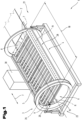
- a device 1 for turning components 2 is shown.
- the device 1 comprises a rotation unit 3 which is designed to turn a component 2 with respect to a rotation axis R in a turning process. It also comprises a conveyor unit 4, wherein the conveyor unit 4 is accommodated in the rotation unit 3 and can be rotated with respect to the rotation axis R by means of the rotation unit 3.
- the conveyor unit 4 comprises at least a first conveyor 5 and a second conveyor 6 arranged opposite with respect to the axis of rotation, wherein the first conveyor 5 defines a first conveyor plane 7 and the second conveyor 6 defines a second conveyor plane 8 arranged parallel to the first conveyor plane 7.
- the conveyor unit 4 is designed to receive the component 2 between the first and second conveyor planes 7, 8 with respect to a conveying direction F arranged parallel to the axis of rotation R, so that the component 2 is received between the first and second conveyor 5, 6 for the turning process.
- the conveying levels 7, 8 refer to the support levels formed by the conveying means 5, 6, to which the component 2 is guided during conveyance into the device 1, or which are directly opposite the component 2 on its two flat sides during the turning process itself.
- At least one first stop arrangement 9 is provided, wherein a first stop plane 10 or a stop surface between the first and second conveying means 5, 6 can be formed by means of the stop arrangement 9.
- the stop plane 10 can preferably be aligned perpendicular to the first conveying plane 7 and/or parallel to the
- the stop arrangement 9 is provided for positioning the component 2 during the turning process and is also designed to be adjustable parallel to the first conveying plane 7 and transversely or perpendicularly to the rotation axis R.
- a direction of movement 20 arranged transversely to the rotation axis R and parallel to the first conveying plane 7 is indicated.
- the stop arrangement 9 thus forms a stop for the component 2 so that it cannot slip out or be displaced between the two conveying planes during the turning process due to gravity.
- a stop or a rigid reference 19 can be provided opposite the component 2.
- the component 2 can be displaced by means of the adjustable stop arrangement 9 so that it comes to rest on the rigid reference 19 for the turning process and is thus held immovably between the reference 19 and the stop arrangement 9 or the stop plane 10.
- the stop arrangement 9 is designed such that it does not hinder the component 2 during transport along the conveying direction F into the conveyor unit 4 or out of it. It preferably extends over a total length 18 of the conveyor unit 4 and can be moved out of a receiving area of the conveyor unit 4.
- the stop arrangement 9 can be adjusted by means of a drive means (not shown), which is preferably accommodated in the rotation unit 3. As shown, the stop arrangement 9 can be mounted and guided by means of a rail guide or the like, which is arranged outside the two conveying planes and facing away from them with respect to the component.
- a drive device (not shown) can also be provided for rotating the rotation unit 3 with respect to the rotation axis R, which is coupled, for example, to a belt or gear drive.
- the ring-shaped elements of the rotation unit shown can preferably be rotatably mounted and can be rotated with the conveyor unit about the axis R, or can only have individual segments which are rotatably mounted and coupled with the conveyor unit.
- a control device 30 can preferably be provided, which is connected to the rotation unit 3 and the conveyor unit 4 as well as the stop arrangement 9, so that their movements, preferably dependent on one another, are initiated by the control unit.
- the device for detecting a picked up or dispensed component can have light barriers in the end regions 21, 22, as indicated, which are preferably connected to the control device 30.
- the light barriers can be provided for releasing the stop arrangement 9 or also, for example, for supporting movable conveyor means, so that its operation is supported by the light barriers with regard to component positions, etc.
- the conveyor means can have individual conveyor elements, which are designed as rotatably mounted rollers, for example. Conveyor belts, sliding surfaces or planar surfaces with mounted rolling elements, such as balls, can also be provided. It should be noted that the stop arrangement is not limited to the conveyor means design shown.
- the conveyor unit 4 can have a lateral access opening 28, which is provided for equipping the device with a component 2 transversely to the conveying direction F.
- the access opening 28 can be used to manually insert components without entering adjacent systems of the device 1.
- the access opening 28 is preferably arranged opposite the stop arrangement with respect to the rotation axis R.
- components can be dispensed via the access opening 28 by means of the adjustable stop arrangement 9.
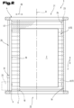
- Fig.2 a plan view of a rotation unit 3 is shown, wherein the first conveying means of the conveying unit 4 is hidden.
- the component 2 is accommodated in the conveyor unit 4 and is located between the two conveyors or the two conveyor levels.
- the stop arrangement 9 is located in the waiting position 26 and can be adjusted to the component 2 in a direction perpendicular to the rotation axis R, and with the stop plane 10 to rest against a longitudinal edge of the component 2, as indicated by dashed lines.
- a detector 31 can be provided, which is preferably connected to the control device.
- the stop arrangement 9 can also have a pressure sensor or the like, by means of which a stop of the component located in the conveyor unit 4 can be determined when the stop arrangement is adjusted, or also a contact of this component during the turning process.
- a pressure sensor or the like by means of which a stop of the component located in the conveyor unit 4 can be determined when the stop arrangement is adjusted, or also a contact of this component during the turning process.
- two spaced-apart sensors can be provided so that a linear contact of the component can be detected.
- a rigid system or reference 19 can be provided opposite the component, e.g. for aligning the component by bringing it closer to the reference by means of the stop arrangement.
- a second stop arrangement 23 with a second stop plane 24 can be arranged opposite the stop arrangement 9 with respect to the rotation axis R, so that a component is accommodated between the two stop arrangements.
- the second stop arrangement can also be adjustable perpendicular to the rotation axis R and would thus be designed essentially symmetrically to the first stop arrangement.
- the two stop arrangements can be adjusted synchronously with one another. With such an arrangement, it can be provided that the component can be centered in the conveyor unit 4 by means of the two stop arrangements.
- At least one of the conveying means can be designed to be movable with respect to the conveying direction F and have a drive means 25.
- the conveying means can also comprise a conveyor belt.
- Fig.2 brush-like elements 41 for receiving the component, which will be discussed in more detail later.
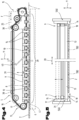
- a preferred embodiment of the conveyor unit 4 in which at least one of the conveyor means, comprising the first conveyor means 5 and second conveyor means 6, comprises individual conveyor elements 13; the conveyor elements 13 are rod-shaped and arranged transversely to the conveying direction F. Furthermore, at least one of the two conveyor means 5, 6 is designed to be relatively movable with respect to the conveying direction F.
- the conveying direction F is preferably parallel to the axis of rotation R.
- the conveying means preferably has a traction drive 17, e.g. an endlessly rotating belt, by means of which traction means the rod-shaped conveying means are coupled to one another so that they can be moved along the conveying direction F.
- a traction drive 17 e.g. an endlessly rotating belt
- At least one deflection arrangement 15 can be provided, wherein by means of the deflection arrangement 15 the at least one movable conveyor can be deflected in such a way that it can be distanced from the other, opposite conveyor, so that at least a partial section 16 of the movable conveyor can be displaced outside the respective conveyor plane.
- the rod-shaped conveyor elements 13 can be moved along the conveying direction F until they reach the deflection arrangement 15 and are distanced from the opposite conveyor by means of the deflection arrangement 15. By means of the deflection arrangement 15, they can be returned, for example, against the original conveying direction.
- the rod-shaped conveying elements 13 have a polygonal, in particular rectangular, cross-section.
- the advantage of this cross-sectional shape is the transverse edge which is formed by the cross-section and which particularly facilitates the insertion of the component and its expulsion from the device.
- the component 2 can be fed to the conveyor unit 4 in the front end region 21 with respect to the conveying direction F, or can be drawn in by the movable conveyor and output to a downstream system in the rear end region 22. Furthermore, the component 2 can also be drawn in and output again in the same end region by means of the movable conveyor.
- the conveyor unit 4 preferably has a drive means 25, which can also be rotated with the conveyor unit 4.
- supply lines 29 can be led to the drive means 25, as shown, which are designed to be flexible so that they are not damaged during rotation.
- the supply lines 29 are preferably connected to a control device 30, which is provided for controlling the entire device 1.
- the rotation unit 3 can comprise at least two ring-shaped elements 36 arranged concentrically to the axis of rotation R, wherein the conveyor unit 4 is accommodated between the two ring-shaped elements 36.
- the ring-shaped elements 36 can preferably be rigidly connected to the conveyor unit 4 and can be rotated, wherein the ring-shaped elements 36 are rotatably accommodated in a bearing arrangement 33.
- a drive unit is preferably provided which is fastened to a rigid part of the device 1.
- a toothing on the ring-shaped elements can be provided in operative connection with the drive unit, or also a belt, a chain or the like.
- the device 1 or the conveyor unit 4 has an adjustable stop arrangement 9 for positioning the component 2 during the turning process, wherein the stop arrangement 9 is adjustable parallel to the first conveyor plane 7 and transversely to the axis of rotation R.
- a stop plane 10 is formed between the first and second conveyor means or between their conveyor plane, which stop plane is preferably perpendicular to these and/or parallel to the axis of rotation R.
- the stop arrangement 9 can preferably be arranged over an entire length 18 of the conveyor unit 4 or the conveyor means.
- the stop arrangement can be mounted at least in the end regions 21, 22 so that it can be adjusted independently of the movement of the at least one movable conveyor.
- the stop arrangement 9 is in a waiting position 26 in the illustration.
- a drive arrangement 27 can preferably be provided, by means of which the stop arrangement 9 can preferably be moved linearly, as in the example shown transversely to the axis of rotation R.
- the drive arrangement 27 can also comprise a type of traction means, as well as other devices known from the prior art which are suitable for adjusting the stop arrangement.
- limiting elements 34 can preferably be provided, which serve, for example, as a stop for a complete rotation.
- stoppers 35 serving as a limiter can be provided on rotatable areas, in particular the ring-shaped elements 32.
- the device can also be rotated over a larger angle, e.g. 360 °.
- both conveying means are designed to be movable, in particular synchronously with one another, so that the component is picked up by both conveying means and can be moved along the conveying direction F.
- the conveyor unit 4 can have an arrangement for adjusting the height of at least one of the conveyor means, so that a distance between the two conveyor means can be adjusted.
- the drive means 25 are preferably designed for this purpose, as well as for driving the traction means by means of the wheels shown.
- the device 1 can also comprise positioning means 37 for determining a position or rotation of the rotation unit 3.
- the means can comprise, for example, an inclination sensor.
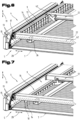
- Fig.4 is an embodiment of a movable conveyor 5 according to Fig.3 shown in side view.
- the conveyor has a traction drive 17, in particular a rotating belt or chain, by means of which the conveyor 5 can be adjusted along the conveying direction F.
- the traction drive can be designed to rotate continuously or also to be interrupted and can be moved between two end positions.
- the rod-shaped conveyor elements 13 are arranged transversely to the axis of rotation R (preferably transversely to the conveying direction F).
- the rod-shaped conveyor elements 13 can preferably be rigidly attached to the traction drive 17 and designed to rotate with it.
- a traction device can be arranged in each of the lateral edge areas of the conveyor unit and the rod-shaped conveyor elements 13 can be attached between two traction devices so that they extend across the width transversely to the conveying direction F of the conveyor unit.
- a push chain or other rotating conveyor devices can also be provided.
- the conveying elements 13 of the conveying means 5 can be designed in such a way that they can circulate endlessly by means of the traction means. However, it can also be the case that they have end stops or the like for conveying a component along the conveying direction F with respect to the direction of rotation of the conveying elements, so that they can only move in a certain direction. area (with respect to their direction of rotation).
- Determination means 38 can be provided to determine the position or an end position.
- the determination means can comprise detectors, magnetic sensors, mechanical switches, etc. Furthermore, these can in turn be connected to the control device. For example, it can be provided that the conveyor elements are in a waiting position for a component to be picked up, and thus a majority or all of the conveyor elements are moved out of the conveyor level and are only moved into the conveyor level with a component when it is picked up.
- the second funding 6 is in Fig.4 indicated by dashed lines and in one embodiment can also be designed to be non-movable and, for example, have rotatably mounted rollers or the like for positioning the component.
- the arrangement of the conveyors shown can also be reversed, so that the movable conveyor is at the bottom, etc.
- the second conveyor can be designed symmetrically to the first.
- the movable conveyor means or the rod-shaped conveyor elements 13 have brush-like elements 41, regardless of the embodiment shown, wherein the brush-like elements are provided for receiving the component 2.
- the brush-like elements 41 are arranged on the surface of the conveyor means 5 facing the component 2.
- the brush-like elements 41 are preferably elastically deformable and can be made of an elastic material such as elastomers or thermoplastics or can also consist of other plastics and other materials. They preferably have a higher static friction with respect to the component, so that they can pick up and take along the component 2 in the movement of the conveying means with respect to the conveying direction F.
- a coating or the like with an increased coefficient of friction can be provided on the surface of the conveying means.
- the component can be drawn into the gap formed in the deflection area of the deflection arrangement 15 by means of the brush-like elements 41, or can also be fed back to an adjacent system in this area.
- the second conveyor means 6 can be designed symmetrically to the first conveyor means 5.
- the drive wheels of the traction drive are adjustable so that the distance of the conveyor to the opposite conveyor can be changed.
- an original position of the rod-shaped conveyor elements 13 is indicated by dashed lines, in which position the conveyor elements were before picking up the component 2, or can be in after a component has been dispensed, so that at least a partial section 16 of the movable conveyor can be displaced outside the respective conveyor plane.
- the rod-shaped conveyor elements 13 are arranged with respect to a length 40 of the traction means 17 only within a traction means section 39, wherein the traction means section 39 is 30% to 60% of the length 40.
- the length 40 of a rotating traction means drive or belt is its total length.
- the stop arrangement can comprise individual stop elements 14, wherein the stop elements 14 are preferably arranged perpendicular to the first conveying plane 7 and are arranged at a distance from one another with respect to a direction parallel to the axis of rotation (R) or in the conveying direction F.
- the stop elements 14 together form the stop plane 10 or stop surface.
- stop elements 14 can each be guided between the rod-shaped conveying elements 13 of the first conveying means 5, preferably at least up to the conveying plane 8 of the opposite second conveying means 6.
- the rod-shaped conveying elements (whether rollers or movable rods) have corresponding gaps which correspond to a spacing of the (parallel) rod-shaped conveying elements from one another, through which the stop elements can be passed, which gaps can generally be seen from the figures.
- stop elements 14 are preferably also can be completely removed from the area of the conveyor elements so that they do not block the conveyor elements in the conveying direction, as can be seen from the Figures 4 to 7 emerges.
- the stop elements 14 of the stop arrangement 9 can also be slidably mounted in the conveying direction F with respect to a clearance, so that the movable conveying means with the rod-shaped conveying elements 13 does not have to be brought into an exact position with respect to the stop elements 14, but can be guided through between the conveying elements 13 by means of the clearance.
- bevels, curves, etc. can be provided on the stop elements.
- the length of the stop arrangement 9 can be selected to be shorter than the total length of the conveyor unit due to the deflection arrangement 15.
- the stop arrangement 9 can extend, for example, between two deflection arrangements 15 of a rotating traction drive 17, but at least with respect to the conveying direction F over a width of two adjacent rod-shaped conveyor elements 13, or over at least two openings between the rod-shaped conveyor elements.
- the rod-shaped conveying elements 13 preferably have a polygonal, in particular a rectangular cross-section, as also shown
- Fig.5 a possible embodiment of a stop arrangement is shown, wherein the stop arrangement 9 is adjustable relative to a vertical direction 11 to the first conveying plane 7.
- the adjustment of the stop arrangement 9 relative to the vertical direction 11 can be carried out by means of a link arrangement, which will be discussed in more detail later.
- the stop arrangement 9 can have individual stop elements 14 as in Fig.4 wherein the stop elements 14 are arranged (and can be guided through) between the rod-shaped conveying elements 13 of the conveying means with respect to the conveying direction F.
- the stop arrangement 9 can thus be adjusted along the vertical direction 11, preferably outside the conveying plane, so that it can be displaced outside the area between the two conveying planes.
- the adjustment of the stop arrangement 9 with respect to the vertical direction 11 can also be carried out via a telescopic arrangement.
- the individual stop elements can be designed to be telescopic and, for example, adjustable via a common drive.
- a conveyor unit 4 comprising a link arrangement 12, wherein the stop arrangement 9 is coupled to the link arrangement 12 in such a way that when the stop arrangement 9 is adjusted to the rotation axis (R), the stop arrangement can be adjusted by means of the link arrangement 12 with respect to the vertical direction 11.
- the stop arrangement with the stop elements is in a position outside the receiving area between the two conveyor levels.
- the adjustment in the vertical direction 11 via the link can preferably be carried out immediately at the beginning of the adjustment of the stop arrangement to the rotation axis, when it is moved from the waiting position and is at the furthest distance from the rotation axis.
- the stop arrangement is then brought into the receiving area, as shown in Fig.7 is shown.
- the link arrangement 12 is preferably arranged on a strut 42 or the like, which is arranged in the conveyor unit 4. As shown, the link is preferably arranged or designed in a plane perpendicular to the axis of rotation.
- the drive means for adjusting the stop arrangement 9 or a guide element 36 of the stop arrangement can be designed as in the previous figures, and the drive means 25 can also preferably be attached to or in the struts 42.
- stop elements 14 can each be guided between the rod-shaped conveyor elements 13, as shown, by means of the link arrangement 12.
- the stop arrangement 9 can in this regard have a lever with a driver, wherein the driver is accommodated in a slide track and is guided by this.
- the stop arrangement 9 can be adjusted in and out in a receiving area for the component 2 between the first and second conveying planes, in that the driver is moved with respect to the The link arrangement 12 is moved into an end position and thus causes the adjustment with respect to the vertical direction 11.
- control device is designed to control the adjustment of the stop arrangement depending on the movement of the conveying means, so that, for example, in the embodiment according to Fig. 6 and 7 the rod-shaped conveyor elements 13 are brought into position for the passage of the stop elements 14.
- the stop arrangement can also have a play parallel to the axis of rotation, so that the stop elements 14 can be guided more easily through the conveyor elements.
- the driver shown can preferably be positively guided along its slide track in such a way that it follows a single possible path movement in the slide by adjusting the stop arrangement transversely to the axis of rotation back and forth.
- This measure assigns a unique position perpendicular to the conveying plane to each position of the stop arrangement transversely to the axis of rotation, which also makes it possible to determine the position of the component.
- the stop elements 14 can preferably be dimensioned with respect to the vertical direction 11 such that, in terms of their length, after adjustment in the direction of the conveying plane 7, they are located between the two conveying means and extend at most up to this conveying plane of the opposite conveying means, so that they do not touch the conveying elements of the opposite conveying means.
- the stop arrangement 9 extends with respect to a direction parallel to the axis of rotation R over at least two rod-shaped conveying elements 13, preferably between 25% and 80% of a total length of the conveying unit or of one of the conveying means.
Landscapes
- Engineering & Computer Science (AREA)
- Mechanical Engineering (AREA)
- Attitude Control For Articles On Conveyors (AREA)
- Registering Or Overturning Sheets (AREA)
Applications Claiming Priority (1)
| Application Number | Priority Date | Filing Date | Title |
|---|---|---|---|
| ATA50796/2022A AT526562B1 (de) | 2022-10-13 | 2022-10-13 | Wendevorrichtung mit einer Anschlaganordnung |
Publications (3)
| Publication Number | Publication Date |
|---|---|
| EP4353379A2 true EP4353379A2 (fr) | 2024-04-17 |
| EP4353379A3 EP4353379A3 (fr) | 2024-07-03 |
| EP4353379B1 EP4353379B1 (fr) | 2026-03-25 |
Family
ID=88412245
Family Applications (1)
| Application Number | Title | Priority Date | Filing Date |
|---|---|---|---|
| EP23203434.8A Active EP4353379B1 (fr) | 2022-10-13 | 2023-10-13 | Dispositif de retournement avec un dispositif de butée |
Country Status (2)
| Country | Link |
|---|---|
| EP (1) | EP4353379B1 (fr) |
| AT (1) | AT526562B1 (fr) |
Cited By (1)
| Publication number | Priority date | Publication date | Assignee | Title |
|---|---|---|---|---|
| CN118143147A (zh) * | 2024-05-09 | 2024-06-07 | 厦门昭唐机床有限公司 | 一种夹持工件转向机构 |
Families Citing this family (1)
| Publication number | Priority date | Publication date | Assignee | Title |
|---|---|---|---|---|
| DE102023131515A1 (de) * | 2023-11-13 | 2025-05-15 | Tünkers Maschinenbau Gmbh | Wendevorrichtung zum Wenden eines Produktionsgutes, Produktionssystem sowie Verfahren |
Citations (1)
| Publication number | Priority date | Publication date | Assignee | Title |
|---|---|---|---|---|
| JP2000079526A (ja) | 1998-07-08 | 2000-03-21 | Amada Co Ltd | ワ―ク加工システム及びこのワ―ク加工システムの使用方法 |
Family Cites Families (13)
| Publication number | Priority date | Publication date | Assignee | Title |
|---|---|---|---|---|
| DE594036C (de) * | 1934-03-09 | Wilhelm Metzger | Foerdereinrichtung mit federnder Gesamtoberflaeche | |
| GB1406251A (en) * | 1972-02-10 | 1975-09-17 | Deritend Eng Co | Feeders for sheet material |
| JPS5928980Y2 (ja) * | 1978-02-28 | 1984-08-21 | ナショナル住宅産業株式会社 | 反転機 |
| DE3009615A1 (de) * | 1980-03-13 | 1981-09-24 | Siegfried 7971 Aichstetten Gebhart | Vorrichtung zum fraesen von bausteinen |
| CH695266A5 (fr) * | 2002-04-03 | 2006-02-28 | Bobst Sa | Dispositif pour retourner des piles de materiau en feuilles. |
| DE102013206698A1 (de) * | 2013-04-15 | 2014-10-16 | Weber Maschinenbau Gmbh Breidenbach | Verfahren und Vorrichtung zum Umorientieren einer Scheibe oder einer Portion eines aufgeschnittenen Lebensmittelprodukts |
| ES2909000T3 (es) * | 2014-07-23 | 2022-05-04 | Laitram Llc | Desviador que se puede limpiar |
| CN106743427A (zh) * | 2016-12-23 | 2017-05-31 | 广州市万世德智能装备科技有限公司 | 一种高速包装生产线 |
| CN107352259A (zh) * | 2017-08-30 | 2017-11-17 | 温岭市正大工业机器人有限公司 | 鼠笼式翻转机 |
| CN208775765U (zh) * | 2018-08-06 | 2019-04-23 | 宁波盈泰利科智能科技有限公司 | 一种发动机改造流水线 |
| CN110857179A (zh) * | 2018-08-24 | 2020-03-03 | 连云港冠创家具有限公司 | 一种翻板机 |
| CN110342222A (zh) * | 2019-07-18 | 2019-10-18 | 珠海市宏泰机械科技有限公司 | 一种全适应板件翻转机构 |
| CN111805494B (zh) * | 2020-07-31 | 2023-06-30 | 邵东智能制造技术研究院有限公司 | 工件翻转加工装置 |
-
2022
- 2022-10-13 AT ATA50796/2022A patent/AT526562B1/de active
-
2023
- 2023-10-13 EP EP23203434.8A patent/EP4353379B1/fr active Active
Patent Citations (1)
| Publication number | Priority date | Publication date | Assignee | Title |
|---|---|---|---|---|
| JP2000079526A (ja) | 1998-07-08 | 2000-03-21 | Amada Co Ltd | ワ―ク加工システム及びこのワ―ク加工システムの使用方法 |
Cited By (1)
| Publication number | Priority date | Publication date | Assignee | Title |
|---|---|---|---|---|
| CN118143147A (zh) * | 2024-05-09 | 2024-06-07 | 厦门昭唐机床有限公司 | 一种夹持工件转向机构 |
Also Published As
| Publication number | Publication date |
|---|---|
| EP4353379A3 (fr) | 2024-07-03 |
| AT526562B1 (de) | 2026-02-15 |
| AT526562A1 (de) | 2024-04-15 |
| EP4353379B1 (fr) | 2026-03-25 |
Similar Documents
| Publication | Publication Date | Title |
|---|---|---|
| EP4353379A2 (fr) | Dispositif de retournement avec un dispositif de butée | |
| DE69203528T2 (de) | Fördervorrichtung für Artikel. | |
| DE68909001T2 (de) | Vorrichtung zur Einstellung von Glastafeln. | |
| EP3678964B1 (fr) | Dispositif et procédé d'orientation de lots de produits | |
| DE2611556A1 (de) | Automatisches sortierfoerdersystem | |
| EP0222344A2 (fr) | Dispositif à tester et à trier des composants électroniques | |
| DE2745298C2 (de) | Vorrichtung zum Fördern und Verteilen von Gegenständen | |
| EP0164063A2 (fr) | Machine-outil pour l'usinage des planches | |
| EP3368452B1 (fr) | Station d'orientation permettant d'orienter un article à transporter transporté dans un système de transport | |
| EP0204291A2 (fr) | Dispositif à tester et trier des composants électroniques, en particulier des puces intégrées | |
| DE102020102019A1 (de) | Modularer Bandförderer | |
| AT526555A2 (de) | Vorrichtung zum Wenden von Bauteilen | |
| DE102020105062A1 (de) | Drucker zum Bedrucken von Markierer-Karten mit Markierern zum Markieren elektrischer Geräte | |
| DE10041241B4 (de) | Ausricht- und Zuführeinrichtung für plattenartige Werkstücke | |
| EP0933580A2 (fr) | Dispositif d'arrêt | |
| EP3715286B1 (fr) | Protection ajustable contre le coincement d'une bande transporteuse | |
| EP1895364B1 (fr) | Dispositif et procédé de lecture de plaques de phosphore de stockage | |
| DE29520112U1 (de) | Vorrichtung zum Trennen und seitlichem Auslenken durch Längsschnitt erzeugten Metallstreifen | |
| DE19960347C2 (de) | Vorrichtung zum Ablenken eines Schuppenstroms auf einem Rolltisch | |
| EP1218271B1 (fr) | Dispositif pour tourner une pile de papier | |
| EP0547298B1 (fr) | Balance de précision | |
| DE20214860U1 (de) | Bandförderer mit Ausschleuseinrichtung | |
| AT518997B1 (de) | Vorrichtung zum Bearbeiten und Transportieren von Teigbändern | |
| DE102020112222A1 (de) | Prüfanlage für eine Mehrzahl von vereinzelbaren Prüfobjekten | |
| DE102023134598B3 (de) | Motorrollen-Umlenkförderer in Kassettenbauweise |
Legal Events
| Date | Code | Title | Description |
|---|---|---|---|
| PUAI | Public reference made under article 153(3) epc to a published international application that has entered the european phase |
Free format text: ORIGINAL CODE: 0009012 |
|
| STAA | Information on the status of an ep patent application or granted ep patent |
Free format text: STATUS: THE APPLICATION HAS BEEN PUBLISHED |
|
| AK | Designated contracting states |
Kind code of ref document: A2 Designated state(s): AL AT BE BG CH CY CZ DE DK EE ES FI FR GB GR HR HU IE IS IT LI LT LU LV MC ME MK MT NL NO PL PT RO RS SE SI SK SM TR |
|
| PUAL | Search report despatched |
Free format text: ORIGINAL CODE: 0009013 |
|
| AK | Designated contracting states |
Kind code of ref document: A3 Designated state(s): AL AT BE BG CH CY CZ DE DK EE ES FI FR GB GR HR HU IE IS IT LI LT LU LV MC ME MK MT NL NO PL PT RO RS SE SI SK SM TR |
|
| RIC1 | Information provided on ipc code assigned before grant |
Ipc: B21D 43/26 20060101ALN20240529BHEP Ipc: B21D 43/12 20060101ALN20240529BHEP Ipc: B65G 47/248 20060101ALI20240529BHEP Ipc: B21D 43/14 20060101AFI20240529BHEP |
|
| STAA | Information on the status of an ep patent application or granted ep patent |
Free format text: STATUS: REQUEST FOR EXAMINATION WAS MADE |
|
| 17P | Request for examination filed |
Effective date: 20241212 |
|
| GRAP | Despatch of communication of intention to grant a patent |
Free format text: ORIGINAL CODE: EPIDOSNIGR1 |
|
| STAA | Information on the status of an ep patent application or granted ep patent |
Free format text: STATUS: GRANT OF PATENT IS INTENDED |
|
| RIC1 | Information provided on ipc code assigned before grant |
Ipc: B21D 43/14 20060101AFI20251009BHEP Ipc: B65G 47/248 20060101ALI20251009BHEP Ipc: B21D 43/12 20060101ALN20251009BHEP Ipc: B21D 43/26 20060101ALN20251009BHEP |
|
| INTG | Intention to grant announced |
Effective date: 20251020 |
|
| GRAS | Grant fee paid |
Free format text: ORIGINAL CODE: EPIDOSNIGR3 |
|
| GRAA | (expected) grant |
Free format text: ORIGINAL CODE: 0009210 |
|
| STAA | Information on the status of an ep patent application or granted ep patent |
Free format text: STATUS: THE PATENT HAS BEEN GRANTED |
|
| AK | Designated contracting states |
Kind code of ref document: B1 Designated state(s): AL AT BE BG CH CY CZ DE DK EE ES FI FR GB GR HR HU IE IS IT LI LT LU LV MC ME MK MT NL NO PL PT RO RS SE SI SK SM TR |
|
| REG | Reference to a national code |
Ref country code: CH Ref legal event code: F10 Free format text: ST27 STATUS EVENT CODE: U-0-0-F10-F00 (AS PROVIDED BY THE NATIONAL OFFICE) Effective date: 20260325 Ref country code: GB Ref legal event code: FG4D Free format text: NOT ENGLISH |
|
| REG | Reference to a national code |
Ref country code: DE Ref legal event code: R096 Ref document number: 502023003494 Country of ref document: DE |
|
| REG | Reference to a national code |
Ref country code: IE Ref legal event code: FG4D Free format text: LANGUAGE OF EP DOCUMENT: GERMAN |