EP4353435B1 - Anpassbarer hobel - Google Patents
Anpassbarer hobel Download PDFInfo
- Publication number
- EP4353435B1 EP4353435B1 EP23202176.6A EP23202176A EP4353435B1 EP 4353435 B1 EP4353435 B1 EP 4353435B1 EP 23202176 A EP23202176 A EP 23202176A EP 4353435 B1 EP4353435 B1 EP 4353435B1
- Authority
- EP
- European Patent Office
- Prior art keywords
- blade
- planer
- blades
- shell
- intended
- Prior art date
- Legal status (The legal status is an assumption and is not a legal conclusion. Google has not performed a legal analysis and makes no representation as to the accuracy of the status listed.)
- Active
Links
Images



Classifications
-
- B—PERFORMING OPERATIONS; TRANSPORTING
- B28—WORKING CEMENT, CLAY, OR STONE
- B28D—WORKING STONE OR STONE-LIKE MATERIALS
- B28D1/00—Working stone or stone-like materials, e.g. brick, concrete or glass, not provided for elsewhere; Machines, devices, tools therefor
- B28D1/20—Working stone or stone-like materials, e.g. brick, concrete or glass, not provided for elsewhere; Machines, devices, tools therefor by planing, e.g. channelling by means of planing tools
Definitions
- the field of invention is that of the design and manufacture of tools used by stone cutters.
- the invention concerns the design of a plane, otherwise known in the stonemasonry trade as a "railway plane".
- Planers are planes used to surface soft or even firm stones by scraping.
- planes consist of a wooden body on which steel blades with or without teeth are set.
- the wooden body has a handle allowing the plane to be manipulated by the stonemason.
- These planes can be flat on a straight body when they plane the faces, or shaped when they surmount moldings and/or arches.
- a stonemason usually carries a box in which he has many planes. Such a loaded box can therefore have a relatively heavy weight.
- the blades can become detached from the body or, in the worst case, adopt an unsuitable position which can lead to creating a notch in the stone being worked.
- the invention aims in particular to overcome the drawbacks of the prior art.
- the invention aims to propose a plane whose positioning of the blades on the body guarantees the correct alignment of the blades, quickly and simply.
- the invention also aims to provide a plane which limits the number of tools to be transported and, consequently, the weight of the box which the stonemason must transport to use all the planes he wishes to have.
- planer according to the invention saves significant time on a construction site, while increasing work efficiency since the blades are correctly positioned on the body.
- the blades are easily assembled on the body and can be changed as needed.
- a stonemason only needs to dismantle the body to be able to quickly remove the installed blades and exchange them for new blades or blades of another type.
- the first part forms a base for receiving the second part, and each first fixing member is in the form of a slot intended to be crossed by the fixing portion of a blade.
- the slot makes it easier to fit the blades into the first part of the body since the stonemason only has to insert the blades into the first part of the body using a translational movement.
- the first part of the body as a base for the second part makes it more convenient to assemble the body since the stonemason is guided in assembling the body knowing that the second part comes on top of the first part.
- the first part carries at least one stop for pushing the blade along the insertion axis.
- the thrust stop(s) ensure that a working portion of the blades is always outside the body.
- the second part of the body forms a gripping member of the plane, and each second fixing member is in the form of at least one projection cooperating with a notch of the fixing portion of a blade.
- the second part as a handle allows for a holding force to be exerted on each projection in cooperation with each notch in the blades when the stonemason grasps the plane.
- the second part of the body comprises a first shell and a second shell intended to close the first shell.
- both shells makes it easy to assemble the second part of the body.
- the stonemason only has to position the second shell to close the first shell and thus keep the blades attached to the body.
- the fixing portion of each blade comprises two notches and each of the first shell and the second shell has a projection intended to cooperate with one of the notches.
- the presence of the two projections further ensures that the blades are retained in the body.
- the projections being directed towards each other, they act in compression on the blade to ensure its maintenance in the body.
- the body comprises a plurality of sections abutting each other.
- each section has at least one assembly face provided with a male assembly member, or a female assembly member.
- the male and female assembly parts allow for quick and easy assembly as they avoid any risk of error during assembly.
- This architecture allows for a quarter-turn type assembly, which does not require the use of tools and offers good robustness allowing the stone cutter to work in complete safety.
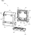
- planer 100 according to the invention is illustrated.
- the planer 100 comprises a body 200 and a plurality of blades 300 intended to be mounted on the body 200.
- each blade 300 has a fixing portion 310 and a working portion 320 intended to extend beyond the body 200.
- the first part 210 integrates, for each blade 300, a first fixing member 240 intended to cooperate with the fixing portion 310.
- first fixing member 240 and the fixing portion 310 of a blade 300 forms a sliding connection along an insertion axis A of the blade in the first part 210.
- the first part 210 of the body 200 forms a base for receiving the second part 220.
- Each first fixing member 240 is in the form of a slot intended to be passed through by the fixing portion 310 of a blade 300.
- the first part 210 of the body 200 carries at least one stop 241 for driving the blade 300 along the insertion axis A.
- the fixing portion 310 of the blades 300 has at least one imprint 340 intended to cooperate with a stop 241.
- each blade 300 has a notch 330 intended to extend above the first part of the body 200 along the insertion axis A when the blade 300 is inserted into the first part 210 of the body 200.
- the second part 220 of the body 200 integrates for each blade 300 a second fixing member 250, intended to cooperate with the fixing portion 310 of each blade 300 to block the blades 300 relative to the body 200 along the insertion axis A.
- the second fixing member 250 is in the form of at least one projection cooperating with a notch 330 of the fixing portion 310 of a blade 300.
- the second part 220 of the body 200 comprises a first shell 221 and a second shell 222 intended to close the first shell 221.
- At least one of the first shell 221 and the second shell 222 comprises a tapped insert 231 allowing the fixing, through a counterbored hole 232 carried by the other of the second shell 222 and the first shell 221, of the fixing means 230 which then take the form of screws.
- the second part 220 of the body 200 forms a gripping member of the plane 100 allowing a user to handle it easily.
- the second part of the body 200 may have a handle P facilitating the gripping of the plane 100 by a user.
- each blade 300 comprises two notches 330 opposite each other relative to the insertion axis A.
- each of the first shell 221 and the second shell 222 has a projection intended to cooperate with one of the notches 330.
- the second fixing member 250 is carried by each of the first shell 221 and the second shell 222 of the body 200.
- the cooperation between the second fixing member 250 and the fixing portion 310 of the blade is male/female type.
- the female part is formed by the notches 330 of the blades 300 and the male part is formed by the second fixing member 250, that is to say by the projection(s) carried by the second part 220 of the body 200.
- male/female cooperation could be reversed.
- the notches could be carried by the second part 220 of the body 200 and the projections could be carried by the fixing portion 310 of the blades 300.
- the body 200 comprises a plurality of sections T abutting each other.
- the plane 100 illustrated is a simple type plane, that is to say whose body 200 comprises a single section T.
- planer 100 having a body 200 comprising a plurality of sections T could be preferred.
- each section T has at least one assembly face 270 provided with a male assembly member 271 or a female assembly member 272.
- the male assembly member 271 is in the form of a pin having a rod 2711 for connections to the assembly phase 270 and a head 2712.
- Head 2712 has a contour having at least one flat surface.
- the outline of the head 2712 is diamond-shaped with rounded corners.
- the female assembly member 272 is in the form of an opening complementary in shape to the head 2712 of the pin.
- assembly face 270 having a female assembly member 272 may have a rotation stop 273 of the two sections T relative to each other. This makes it possible in particular to guarantee the correct positioning of two sections T relative to each other when they are assembled. In addition, this ensures the correct positioning of all the blades 300 of the planer 100 relative to each other.
- each blade 300 is inserted into a first fixing member 240 of the first part 210 of the body 200.
- This first step has the effect of only authorizing the movement of the blades 300 relative to the first part 210 of the body 200 according to a translation movement M1 along the insertion axis A.
- the first shell 221 and the second shell 222 are brought onto the first part 210 of the body 200, according to the translational movements M2 and M3, so that the first part 210 supports the second part 220 of the body.
- the cooperation between the second fixing member 250 and each notch 330 makes it possible to block the blades 300 relative to the body 200 along the insertion axis A.
- the fixing means 230 are then used to block the first shell 221 and the second shell 222 relative to each other.
- the first part 210 is blocked on the blades 300 by the presence of the second part 220 of the body 200, and of each stop 241 which is received in an imprint 340 of a blade 300.
- the planer 100 according to the invention can thus be easily and quickly adapted to different types of work by a rapid change of the blades 300 and/or by the constitution of a body 200 comprising a plurality of sections T.
- stone cutters only have to carry a box containing different types of blades 300 which can be mounted on the same body 200 of the plane 100 quickly and easily.
Landscapes
- Engineering & Computer Science (AREA)
- Mining & Mineral Resources (AREA)
- Mechanical Engineering (AREA)
- Milling, Drilling, And Turning Of Wood (AREA)
- Gripping Jigs, Holding Jigs, And Positioning Jigs (AREA)
- Workshop Equipment, Work Benches, Supports, Or Storage Means (AREA)
- Harvester Elements (AREA)
Claims (10)
- Hobel (100), der Folgendes umfasst:- einen Körper (200),- eine Vielzahl von Klingen (300), die auf dem Körper (200) montiert sind, wobei jede Klinge (300) einen Befestigungsabschnitt (310) aufweist,wobei der Körper (200) Folgendes umfasst:- einen ersten Teil (210), der für jede Klinge (300) ein erstes Befestigungsbauteil (240) integriert, das dazu bestimmt ist, mit dem Befestigungsabschnitt (310) zusammenzuwirken, um eine Gleitverbindung entlang einer Einsetzachse (A) der Klinge (300) in den ersten Teil (210) zu bilden; dadurch gekennzeichnet, dass der Körper (200) Folgendes umfasst.- einen zweiten Teil (220), der für jede Klinge (300) ein zweites Befestigungsbauteil (250) integriert, das dazu bestimmt ist, mit dem Befestigungsabschnitt (310) zusammenzuwirken, um die Klinge (300) in Bezug auf den Körper (200) entlang der Einsetzachse (A) zu blockieren,- Mittel zum Montieren (230) des ersten Teils (210) mit dem zweiten Teil (220) .
- Hobel (100) nach Anspruch 1, dadurch gekennzeichnet, dass der erste Teil (210) einen Sockel zur Aufnahme des zweiten Teils (220) bildet und jedes erste Befestigungsbauteil (240) in Form eines Schlitzes vorliegt, der dazu bestimmt ist, vom Befestigungsabschnitt (310) einer Klinge (300) durchquert zu werden.
- Hobel (100) nach dem vorhergehenden Anspruch, dadurch gekennzeichnet, dass der erste Teil (210) mindestens einen Anschlag (241) zum Eintreiben der Klinge (300) entlang der Einsetzachse (A) trägt.
- Hobel (100) nach einem der vorhergehenden Ansprüche, dadurch gekennzeichnet, dass der zweite Teil (220) des Körpers (200) ein Bauteil zum Greifen des Hobels (100) bildet und dass jedes zweite Befestigungsbauteil (250) in Form mindestens eines Vorsprungs vorliegt, der mit einer Aussparung (330) des Befestigungsabschnitts (310) einer Klinge (300) zusammenwirkt.
- Hobel (100) nach einem der vorhergehenden Ansprüche, dadurch gekennzeichnet, dass der zweite Teil (220) des Körpers (200) eine erste Schale (221) und eine zweite Schale (222), die dazu bestimmt ist, die erste Schale (221) zu verschließen, umfasst.
- Hobel (100) nach den Ansprüchen 3 und 4, dadurch gekennzeichnet, dass der Befestigungsabschnitt (310) jeder Klinge (300) zwei Aussparungen (330) umfasst und dass jede der ersten Schale (221) und der zweiten Schale (222) einen Vorsprung aufweist, der dazu bestimmt ist, mit einer der Aussparungen (330) zusammenzuwirken.
- Hobel (100) nach einem der vorhergehenden Ansprüche, dadurch gekennzeichnet, dass der Körper (200) eine Vielzahl von Teilabschnitten (T) umfasst, die aneinander stoßen.
- Hobel (100) nach dem vorhergehenden Anspruch, dadurch gekennzeichnet, dass jeder Teilabschnitt (T) mindestens eine Montagefläche (270) aufweist, die mit einem männlichen Montagebauteil (271) oder einem weiblichen Montagebauteil (272) versehen ist.
- Hobel (100) nach dem vorhergehenden Anspruch, dadurch gekennzeichnet, dass das männliche Montagebauteil (271) in Form eines Stifts vorliegt, der einen Schaft (2711) zur Verbindung mit der Montagefläche (270) und einen Kopf (2712) aufweist, und das weibliche Montagebauteil (272) in Form einer Öffnung vorliegt, die in ihrer Form komplementär zum Kopf (2712) des Stifts ist und in der Montagefläche (270) ausgebildet ist.
- Hobel (100) nach dem vorhergehenden Anspruch, dadurch gekennzeichnet, dass der Kopf (2712) eine Kontur mit mindestens einer Abflachung aufweist.
Priority Applications (1)
| Application Number | Priority Date | Filing Date | Title |
|---|---|---|---|
| HRP20241739TT HRP20241739T1 (hr) | 2022-10-14 | 2023-10-06 | Prilagodljivi alat za blanjanje |
Applications Claiming Priority (1)
| Application Number | Priority Date | Filing Date | Title |
|---|---|---|---|
| FR2210564A FR3140788B1 (fr) | 2022-10-14 | 2022-10-14 | Rabotin adaptable |
Publications (3)
| Publication Number | Publication Date |
|---|---|
| EP4353435A1 EP4353435A1 (de) | 2024-04-17 |
| EP4353435B1 true EP4353435B1 (de) | 2024-12-11 |
| EP4353435C0 EP4353435C0 (de) | 2024-12-11 |
Family
ID=84569786
Family Applications (1)
| Application Number | Title | Priority Date | Filing Date |
|---|---|---|---|
| EP23202176.6A Active EP4353435B1 (de) | 2022-10-14 | 2023-10-06 | Anpassbarer hobel |
Country Status (4)
| Country | Link |
|---|---|
| EP (1) | EP4353435B1 (de) |
| ES (1) | ES3008692T3 (de) |
| FR (1) | FR3140788B1 (de) |
| HR (1) | HRP20241739T1 (de) |
Family Cites Families (5)
| Publication number | Priority date | Publication date | Assignee | Title |
|---|---|---|---|---|
| US477693A (en) * | 1892-06-28 | Hand implement for tooling stone-surfaces | ||
| CH243993A (fr) * | 1944-07-14 | 1946-08-31 | Guglielmetti Roch | Rabot pour le travail de la pierre. |
| CH261923A (fr) * | 1949-01-05 | 1949-06-15 | Herzog Christian | Outil pour tailler les pierres. |
| CH658621A5 (en) * | 1984-08-30 | 1986-11-28 | Usines Metallurg De Vallorbe | Hand tool for making grooves, notches or linear shaped mouldings |
| FR2651459B1 (fr) * | 1989-09-05 | 1991-10-31 | Degardin Francois | Dispositif de taille de pierre ou autre du type, a divers jeux de lames profilees, amovibles mecaniquement. |
-
2022
- 2022-10-14 FR FR2210564A patent/FR3140788B1/fr active Active
-
2023
- 2023-10-06 ES ES23202176T patent/ES3008692T3/es active Active
- 2023-10-06 HR HRP20241739TT patent/HRP20241739T1/hr unknown
- 2023-10-06 EP EP23202176.6A patent/EP4353435B1/de active Active
Also Published As
| Publication number | Publication date |
|---|---|
| FR3140788B1 (fr) | 2024-08-30 |
| EP4353435A1 (de) | 2024-04-17 |
| HRP20241739T1 (hr) | 2025-02-28 |
| FR3140788A1 (fr) | 2024-04-19 |
| EP4353435C0 (de) | 2024-12-11 |
| ES3008692T3 (en) | 2025-03-24 |
Similar Documents
| Publication | Publication Date | Title |
|---|---|---|
| EP0782903B1 (de) | Mehrzweckwerkzeug zur Aufnahme abnehmbarer Werkzeuge | |
| EP0931628A1 (de) | Merhzwecktaschenwerkzeug | |
| FR2565865A1 (fr) | Mandrin de serrage de pieces, et mors rapporte, ensemble de mors et dispositif de fixation de mors pour ce mandrin | |
| FR2910365A1 (fr) | Systeme d'outil motorise a cliquet a douille | |
| EP0362007B1 (de) | Universalspannklotz zum Kopieren von Flachschlüsseln | |
| FR3140788A1 (fr) | Rabotin adaptable | |
| EP0869862B1 (de) | Verstellbare zange | |
| EP0567050A1 (de) | Schutterstütze für eine Violine | |
| FR2551684A1 (fr) | Ensemble de poste d'outils pour machines-outils | |
| FR2881368A1 (fr) | Dispositif de reglage de la semelle d'une scie sauteuse | |
| FR2660229A1 (fr) | Outil a usages multiples. | |
| FR3089840A1 (fr) | Pièce de liaison | |
| EP2100572B1 (de) | Dynamometrisches Instrument mit abnehmbarem Kopf | |
| EP4059468B1 (de) | Hilfsvorrichtung für die bearbeitung eines zahnprothesenrohlings | |
| EP1476064A1 (de) | Entfernbarer griff für ein kochutensil | |
| WO2008056072A2 (fr) | Couteau a lame amovible a manche en deux parties separables | |
| EP3093111A1 (de) | Schneidewerkzeug mit abnehmbarer klinge, und klinge für dieses werkzeug | |
| FR2867708A1 (fr) | Porte-outil rotatif a plaquette dissymetrique | |
| FR2996795A1 (fr) | Dispositif de support d'une serie de cles | |
| FR3129312A3 (fr) | Rabotin modulaire | |
| FR2811696A1 (fr) | Ferrure de verrouillage d'ouvrant a mors d'appui interieur manoeuvrable en translation, procede de montage et ouvrant equipe d'une telle ferrure | |
| EP3431034A1 (de) | Unterelement für zahnärztliches oder chirurgisches handstück, zahnärztliches oder chirurgisches handstück und entsprechendes montageverfahren | |
| FR2746044A1 (fr) | Outil a plaquettes interchangeables affutables et procede d'affutage des plaquettes de coupe | |
| FR3142925A1 (fr) | Guide de vissage pour la fixation d’un composant d’un véhicule automobile | |
| CH721957A2 (fr) | Plaquette d'usinage, porte-plaquette et ensemble d'usinage |
Legal Events
| Date | Code | Title | Description |
|---|---|---|---|
| REG | Reference to a national code |
Ref country code: HR Ref legal event code: TUEP Ref document number: P20241739T Country of ref document: HR |
|
| PUAI | Public reference made under article 153(3) epc to a published international application that has entered the european phase |
Free format text: ORIGINAL CODE: 0009012 |
|
| STAA | Information on the status of an ep patent application or granted ep patent |
Free format text: STATUS: THE APPLICATION HAS BEEN PUBLISHED |
|
| STAA | Information on the status of an ep patent application or granted ep patent |
Free format text: STATUS: REQUEST FOR EXAMINATION WAS MADE |
|
| AK | Designated contracting states |
Kind code of ref document: A1 Designated state(s): AL AT BE BG CH CY CZ DE DK EE ES FI FR GB GR HR HU IE IS IT LI LT LU LV MC ME MK MT NL NO PL PT RO RS SE SI SK SM TR |
|
| 17P | Request for examination filed |
Effective date: 20240409 |
|
| RBV | Designated contracting states (corrected) |
Designated state(s): AL AT BE BG CH CY CZ DE DK EE ES FI FR GB GR HR HU IE IS IT LI LT LU LV MC ME MK MT NL NO PL PT RO RS SE SI SK SM TR |
|
| GRAP | Despatch of communication of intention to grant a patent |
Free format text: ORIGINAL CODE: EPIDOSNIGR1 |
|
| STAA | Information on the status of an ep patent application or granted ep patent |
Free format text: STATUS: GRANT OF PATENT IS INTENDED |
|
| INTG | Intention to grant announced |
Effective date: 20240826 |
|
| GRAS | Grant fee paid |
Free format text: ORIGINAL CODE: EPIDOSNIGR3 |
|
| GRAA | (expected) grant |
Free format text: ORIGINAL CODE: 0009210 |
|
| STAA | Information on the status of an ep patent application or granted ep patent |
Free format text: STATUS: THE PATENT HAS BEEN GRANTED |
|
| AK | Designated contracting states |
Kind code of ref document: B1 Designated state(s): AL AT BE BG CH CY CZ DE DK EE ES FI FR GB GR HR HU IE IS IT LI LT LU LV MC ME MK MT NL NO PL PT RO RS SE SI SK SM TR |
|
| REG | Reference to a national code |
Ref country code: GB Ref legal event code: FG4D Free format text: NOT ENGLISH |
|
| REG | Reference to a national code |
Ref country code: CH Ref legal event code: EP |
|
| REG | Reference to a national code |
Ref country code: IE Ref legal event code: FG4D Free format text: LANGUAGE OF EP DOCUMENT: FRENCH |
|
| REG | Reference to a national code |
Ref country code: DE Ref legal event code: R096 Ref document number: 602023001334 Country of ref document: DE |
|
| U01 | Request for unitary effect filed |
Effective date: 20241211 |
|
| U07 | Unitary effect registered |
Designated state(s): AT BE BG DE DK EE FI FR IT LT LU LV MT NL PT RO SE SI Effective date: 20241217 |
|
| REG | Reference to a national code |
Ref country code: GR Ref legal event code: EP Ref document number: 20240402939 Country of ref document: GR Effective date: 20250120 |
|
| REG | Reference to a national code |
Ref country code: HR Ref legal event code: T1PR Ref document number: P20241739 Country of ref document: HR |
|
| REG | Reference to a national code |
Ref country code: ES Ref legal event code: FG2A Ref document number: 3008692 Country of ref document: ES Kind code of ref document: T3 Effective date: 20250324 |
|
| PG25 | Lapsed in a contracting state [announced via postgrant information from national office to epo] |
Ref country code: NO Free format text: LAPSE BECAUSE OF FAILURE TO SUBMIT A TRANSLATION OF THE DESCRIPTION OR TO PAY THE FEE WITHIN THE PRESCRIBED TIME-LIMIT Effective date: 20250311 |
|
| PG25 | Lapsed in a contracting state [announced via postgrant information from national office to epo] |
Ref country code: RS Free format text: LAPSE BECAUSE OF FAILURE TO SUBMIT A TRANSLATION OF THE DESCRIPTION OR TO PAY THE FEE WITHIN THE PRESCRIBED TIME-LIMIT Effective date: 20250311 |
|
| PG25 | Lapsed in a contracting state [announced via postgrant information from national office to epo] |
Ref country code: SM Free format text: LAPSE BECAUSE OF FAILURE TO SUBMIT A TRANSLATION OF THE DESCRIPTION OR TO PAY THE FEE WITHIN THE PRESCRIBED TIME-LIMIT Effective date: 20241211 |
|
| PG25 | Lapsed in a contracting state [announced via postgrant information from national office to epo] |
Ref country code: PL Free format text: LAPSE BECAUSE OF FAILURE TO SUBMIT A TRANSLATION OF THE DESCRIPTION OR TO PAY THE FEE WITHIN THE PRESCRIBED TIME-LIMIT Effective date: 20241211 |
|
| PG25 | Lapsed in a contracting state [announced via postgrant information from national office to epo] |
Ref country code: IS Free format text: LAPSE BECAUSE OF FAILURE TO SUBMIT A TRANSLATION OF THE DESCRIPTION OR TO PAY THE FEE WITHIN THE PRESCRIBED TIME-LIMIT Effective date: 20250411 |
|
| PG25 | Lapsed in a contracting state [announced via postgrant information from national office to epo] |
Ref country code: SK Free format text: LAPSE BECAUSE OF FAILURE TO SUBMIT A TRANSLATION OF THE DESCRIPTION OR TO PAY THE FEE WITHIN THE PRESCRIBED TIME-LIMIT Effective date: 20241211 |
|
| PLBE | No opposition filed within time limit |
Free format text: ORIGINAL CODE: 0009261 |
|
| STAA | Information on the status of an ep patent application or granted ep patent |
Free format text: STATUS: NO OPPOSITION FILED WITHIN TIME LIMIT |
|
| U20 | Renewal fee for the european patent with unitary effect paid |
Year of fee payment: 3 Effective date: 20251009 |
|
| 26N | No opposition filed |
Effective date: 20250912 |
|
| PGFP | Annual fee paid to national office [announced via postgrant information from national office to epo] |
Ref country code: TR Payment date: 20251003 Year of fee payment: 3 Ref country code: GR Payment date: 20251013 Year of fee payment: 3 |
|
| PGFP | Annual fee paid to national office [announced via postgrant information from national office to epo] |
Ref country code: CZ Payment date: 20251003 Year of fee payment: 3 |
|
| PGFP | Annual fee paid to national office [announced via postgrant information from national office to epo] |
Ref country code: ES Payment date: 20251104 Year of fee payment: 3 |
|
| REG | Reference to a national code |
Ref country code: HR Ref legal event code: PBON Ref document number: P20241739 Country of ref document: HR Effective date: 20251006 |