EP4353487B1 - Affichage 3d, authentificateur et procédé de formation - Google Patents
Affichage 3d, authentificateur et procédé de formation Download PDFInfo
- Publication number
- EP4353487B1 EP4353487B1 EP22820226.3A EP22820226A EP4353487B1 EP 4353487 B1 EP4353487 B1 EP 4353487B1 EP 22820226 A EP22820226 A EP 22820226A EP 4353487 B1 EP4353487 B1 EP 4353487B1
- Authority
- EP
- European Patent Office
- Prior art keywords
- region
- dimensional display
- reconstructed image
- display according
- element cells
- Prior art date
- Legal status (The legal status is an assumption and is not a legal conclusion. Google has not performed a legal analysis and makes no representation as to the accuracy of the status listed.)
- Active
Links
Images








Classifications
-
- G—PHYSICS
- G02—OPTICS
- G02B—OPTICAL ELEMENTS, SYSTEMS OR APPARATUS
- G02B30/00—Optical systems or apparatus for producing three-dimensional [3D] effects, e.g. stereoscopic images
- G02B30/40—Optical systems or apparatus for producing three-dimensional [3D] effects, e.g. stereoscopic images giving the observer of a single two-dimensional [2D] image a perception of depth
-
- B—PERFORMING OPERATIONS; TRANSPORTING
- B42—BOOKBINDING; ALBUMS; FILES; SPECIAL PRINTED MATTER
- B42D—BOOKS; BOOK COVERS; LOOSE LEAVES; PRINTED MATTER CHARACTERISED BY IDENTIFICATION OR SECURITY FEATURES; PRINTED MATTER OF SPECIAL FORMAT OR STYLE NOT OTHERWISE PROVIDED FOR; DEVICES FOR USE THEREWITH AND NOT OTHERWISE PROVIDED FOR; MOVABLE-STRIP WRITING OR READING APPARATUS
- B42D25/00—Information-bearing cards or sheet-like structures characterised by identification or security features; Manufacture thereof
- B42D25/20—Information-bearing cards or sheet-like structures characterised by identification or security features; Manufacture thereof characterised by a particular use or purpose
- B42D25/23—Identity cards
-
- B—PERFORMING OPERATIONS; TRANSPORTING
- B42—BOOKBINDING; ALBUMS; FILES; SPECIAL PRINTED MATTER
- B42D—BOOKS; BOOK COVERS; LOOSE LEAVES; PRINTED MATTER CHARACTERISED BY IDENTIFICATION OR SECURITY FEATURES; PRINTED MATTER OF SPECIAL FORMAT OR STYLE NOT OTHERWISE PROVIDED FOR; DEVICES FOR USE THEREWITH AND NOT OTHERWISE PROVIDED FOR; MOVABLE-STRIP WRITING OR READING APPARATUS
- B42D25/00—Information-bearing cards or sheet-like structures characterised by identification or security features; Manufacture thereof
- B42D25/30—Identification or security features, e.g. for preventing forgery
- B42D25/328—Diffraction gratings; Holograms
-
- B—PERFORMING OPERATIONS; TRANSPORTING
- B42—BOOKBINDING; ALBUMS; FILES; SPECIAL PRINTED MATTER
- B42D—BOOKS; BOOK COVERS; LOOSE LEAVES; PRINTED MATTER CHARACTERISED BY IDENTIFICATION OR SECURITY FEATURES; PRINTED MATTER OF SPECIAL FORMAT OR STYLE NOT OTHERWISE PROVIDED FOR; DEVICES FOR USE THEREWITH AND NOT OTHERWISE PROVIDED FOR; MOVABLE-STRIP WRITING OR READING APPARATUS
- B42D25/00—Information-bearing cards or sheet-like structures characterised by identification or security features; Manufacture thereof
- B42D25/30—Identification or security features, e.g. for preventing forgery
- B42D25/36—Identification or security features, e.g. for preventing forgery comprising special materials
- B42D25/378—Special inks
-
- B—PERFORMING OPERATIONS; TRANSPORTING
- B42—BOOKBINDING; ALBUMS; FILES; SPECIAL PRINTED MATTER
- B42D—BOOKS; BOOK COVERS; LOOSE LEAVES; PRINTED MATTER CHARACTERISED BY IDENTIFICATION OR SECURITY FEATURES; PRINTED MATTER OF SPECIAL FORMAT OR STYLE NOT OTHERWISE PROVIDED FOR; DEVICES FOR USE THEREWITH AND NOT OTHERWISE PROVIDED FOR; MOVABLE-STRIP WRITING OR READING APPARATUS
- B42D25/00—Information-bearing cards or sheet-like structures characterised by identification or security features; Manufacture thereof
- B42D25/40—Manufacture
- B42D25/405—Marking
-
- B—PERFORMING OPERATIONS; TRANSPORTING
- B42—BOOKBINDING; ALBUMS; FILES; SPECIAL PRINTED MATTER
- B42D—BOOKS; BOOK COVERS; LOOSE LEAVES; PRINTED MATTER CHARACTERISED BY IDENTIFICATION OR SECURITY FEATURES; PRINTED MATTER OF SPECIAL FORMAT OR STYLE NOT OTHERWISE PROVIDED FOR; DEVICES FOR USE THEREWITH AND NOT OTHERWISE PROVIDED FOR; MOVABLE-STRIP WRITING OR READING APPARATUS
- B42D25/00—Information-bearing cards or sheet-like structures characterised by identification or security features; Manufacture thereof
- B42D25/40—Manufacture
- B42D25/405—Marking
- B42D25/43—Marking by removal of material
- B42D25/435—Marking by removal of material using electromagnetic radiation, e.g. laser
-
- B—PERFORMING OPERATIONS; TRANSPORTING
- B42—BOOKBINDING; ALBUMS; FILES; SPECIAL PRINTED MATTER
- B42D—BOOKS; BOOK COVERS; LOOSE LEAVES; PRINTED MATTER CHARACTERISED BY IDENTIFICATION OR SECURITY FEATURES; PRINTED MATTER OF SPECIAL FORMAT OR STYLE NOT OTHERWISE PROVIDED FOR; DEVICES FOR USE THEREWITH AND NOT OTHERWISE PROVIDED FOR; MOVABLE-STRIP WRITING OR READING APPARATUS
- B42D25/00—Information-bearing cards or sheet-like structures characterised by identification or security features; Manufacture thereof
- B42D25/40—Manufacture
- B42D25/45—Associating two or more layers
-
- B—PERFORMING OPERATIONS; TRANSPORTING
- B42—BOOKBINDING; ALBUMS; FILES; SPECIAL PRINTED MATTER
- B42D—BOOKS; BOOK COVERS; LOOSE LEAVES; PRINTED MATTER CHARACTERISED BY IDENTIFICATION OR SECURITY FEATURES; PRINTED MATTER OF SPECIAL FORMAT OR STYLE NOT OTHERWISE PROVIDED FOR; DEVICES FOR USE THEREWITH AND NOT OTHERWISE PROVIDED FOR; MOVABLE-STRIP WRITING OR READING APPARATUS
- B42D25/00—Information-bearing cards or sheet-like structures characterised by identification or security features; Manufacture thereof
- B42D25/40—Manufacture
- B42D25/48—Controlling the manufacturing process
-
- G—PHYSICS
- G02—OPTICS
- G02B—OPTICAL ELEMENTS, SYSTEMS OR APPARATUS
- G02B27/00—Optical systems or apparatus not provided for by any of the groups G02B1/00 - G02B26/00, G02B30/00
- G02B27/42—Diffraction optics, i.e. systems including a diffractive element being designed for providing a diffractive effect
- G02B27/4205—Diffraction optics, i.e. systems including a diffractive element being designed for providing a diffractive effect having a diffractive optical element [DOE] contributing to image formation, e.g. whereby modulation transfer function MTF or optical aberrations are relevant
-
- G—PHYSICS
- G02—OPTICS
- G02B—OPTICAL ELEMENTS, SYSTEMS OR APPARATUS
- G02B5/00—Optical elements other than lenses
- G02B5/18—Diffraction gratings
-
- G—PHYSICS
- G02—OPTICS
- G02B—OPTICAL ELEMENTS, SYSTEMS OR APPARATUS
- G02B5/00—Optical elements other than lenses
- G02B5/32—Holograms used as optical elements
-
- G—PHYSICS
- G03—PHOTOGRAPHY; CINEMATOGRAPHY; ANALOGOUS TECHNIQUES USING WAVES OTHER THAN OPTICAL WAVES; ELECTROGRAPHY; HOLOGRAPHY
- G03H—HOLOGRAPHIC PROCESSES OR APPARATUS
- G03H1/00—Holographic processes or apparatus using light, infrared or ultraviolet waves for obtaining holograms or for obtaining an image from them; Details peculiar thereto
- G03H1/0005—Adaptation of holography to specific applications
- G03H1/0011—Adaptation of holography to specific applications for security or authentication
-
- G—PHYSICS
- G03—PHOTOGRAPHY; CINEMATOGRAPHY; ANALOGOUS TECHNIQUES USING WAVES OTHER THAN OPTICAL WAVES; ELECTROGRAPHY; HOLOGRAPHY
- G03H—HOLOGRAPHIC PROCESSES OR APPARATUS
- G03H1/00—Holographic processes or apparatus using light, infrared or ultraviolet waves for obtaining holograms or for obtaining an image from them; Details peculiar thereto
- G03H1/02—Details of features involved during the holographic process; Replication of holograms without interference recording
Definitions
- the embodiments of the present invention relate to authentication media which are attached to cards, passports, visas, etc., for example, to verify authenticity thereof, three-dimensional displays that can be applied to authentication media, and methods of forming three-dimensional displays.
- ID cards such as passports and driver's licenses
- Most ID cards have facial information and textual information displayed thereon to visually identify personal information.
- personal information simply printed on authentication media is vulnerable to tampering or counterfeiting.
- PTL 1 describes improving the anti-tampering properties of an authentication medium by transferring a hologram foil to the authentication medium.
- the anti-counterfeiting technique described in PTL 1 is already well known and will permit easy counterfeiting of holograms emitting simple iridescent diffraction light.
- PTL 2 describes adding personal information using a fluorescent light-emitting material, so that the personal information is transparent and invisible when observed under visible light but is visible under ultraviolet observation.
- PTL 3 describes, as another anti-counterfeiting method, performing authenticity verification using reproduced information displayed on a hologram by irradiating the hologram with light of a specific wavelength.
- the reproduced information is preset and invariant. Therefore, once a counterfeiter knows the reproduced information, they may produce a hologram imitating the reproduced information.
- laser interference holograms or CGH's (computer generated holograms) using computational laser interference calculation, which are characterized by three-dimensional viewing of the holograms utilizing binocular parallax, can have dynamic effects produced by the observer changing the viewing angle, and therefore, can achieve functions that cannot be achieved by generally used printed matter and thus are applied to various security labels in recent years.
- these types of holograms are characterized in that the image appears to pop out from the medium surface when it is reconstructed under a point light source; however, these holograms have a disadvantage that, if they are illuminated with a generally used elongated fluorescent lamp, multiple light sources, or a light with a large light-emitting surface, the reconstructed image may appear blurred.
- the reconstructed image is characterized in that it has no blur and is easily visible in any environment because the basic pattern appears to be the same to each eye, while the pattern appears to be different in color or luminance to each eye.
- this reconstructed image is disadvantageous in that it lacks stereoscopic effects. These diffraction gratings are not appropriate for machine reading.
- PTL 8 describes a method for producing a multi-layer body having a volume hologram with at least two different image information items.
- a photosensitive layer of the multi-layer body is brought into contact with the front side of a master directly or by interposing a transparent optical medium, into which front side nested areas with different asymmetrical surface structures or kinoform structures are formed which embody the at least two different image information items.
- the photosensitive layer and the master are exposed using a coherent light beam, by means of which a volume hologram is formed in the photosensitive layer.
- PTL 9 describes a security device comprising a transparent layer having a first optically variable effect generating relief structure formed in a surface thereof; a reflection enhancing body extending over the first relief structure and following the contour of the first relief on a first side of the reflection enhancing body; and a second optically variable effect generating relief structure formed in a second side of the reflection enhancing body.
- the present invention has been made in light of the circumstances set forth above and aims to provide a visually and machine readable authentication medium which can suppress tampering or counterfeiting using a simple structure and can facilitate verification of authenticity, and to provide a three-dimensional display that can be applied to the authentication medium, and a method of forming the three-dimensional display.
- a first aspect is a three-dimensional display according to claim 1.
- a second aspect is a three-dimensional display in which a first contour region surrounding a recorded first character, and a second contour region surrounding a recorded second character are arranged on a laminate sheet, wherein a plurality of first element cells in which personal identification information is recorded and a plurality of second element cells carrying an authentication medium from which the personal identification information is visible are arranged in the first contour region and in the second contour region to form respective phase shift structures; in the first contour region and in the second contour region, the first element cells and the second element cells are arranged in an interleaved manner at a predetermined ratio to form respective three-dimensional structures; the first contour region and the second contour region are visible respectively from first and second sides of the laminate sheet; a reconstructed image derived from the second contour region is produced on the first side of the laminate sheet, at a position apparently separated from the laminate sheet, due to the phase shift structure formed by the first element cells; and a reconstructed image derived from the first contour region is produced on the second side of the laminate sheet, at a position apparently separated from the laminate
- a third aspect is the three-dimensional display according to claim 3.
- a fourth aspect is an authentication medium according to claim 16.
- a fifth aspect is a method according to claim 18.
- a visually and machine readable authentication medium which can suppress tampering or counterfeiting with a simple structure and can facilitate verification of authenticity, and to provide a three-dimensional display that can be applied to the authentication medium, and a method of forming the three-dimensional display.
- the first reconstructed image can be produced apparently separated from the first side of the laminate sheet (e.g., the front side as viewed from the observer), and the second reconstructed image can be produced apparently separated from the second side of the laminate sheet (e.g., the rear side as viewed from the observer).
- the stereoscopic effects are achieved only at the reconstruction distance from the surface of the laminate sheet to the single reconstructed image.
- the first reconstructed image produced apparently separated from the front side of the laminate sheet
- the second reconstructed image is produced apparently separated from the rear side, i.e., two reconstructed images are produced. Accordingly, the observer can perceive the reconstruction distance from the reconstruction plane of the second reconstructed image to the reconstruction plane of the first reconstructed image and thus can feel stereoscopic effects, irrespective of the position of the authentication medium present therebetween. Also, this improves anti-counterfeiting properties or aesthetic properties.
- the three-dimensional display of claim 2 as in the three-dimensional display of claim 1, two reconstructed images are produced, on the front and rear sides of the laminate sheet, and accordingly, stereoscopic effects can be achieved, irrespective of the position of the authentication medium present therebetween. Also, this improves anti-counterfeiting properties or aesthetic properties.
- a configuration in which the three-dimensional displays of the first and second claims are combined is provided to further improve stereoscopic effects, anti-counterfeiting effects, and aesthetic properties.
- the three-dimensional displays of the first and second claims can be combined through alignment using the markers provided to the respective laminate sheets.
- the three-dimensional displays of the first and second claims are preferred to have the same area and the same shape.
- the markers can be provided at the boundary between the first element cells and the second element cells.
- the three-dimensional display of the first claim and the three-dimensional display of the second claim can be arranged so that the rear surface of the laminate sheet of the first aspect faces the front surface of the laminate sheet of the second aspect to establish a boundary between the first element cells and the second element cells.
- the three-dimensional displays of the first and second claims are preferred to have the same area and the same shape.
- the first reconstructed image can be made less likely to be blurred, irrespective of the illumination distance, the number of illumination sources, and the illumination size, while conversely, the second reconstructed image can be made observable with only a point light source. Furthermore, the first reconstructed image and the second reconstructed image can be produced adjacent to each other, so that the first reconstructed image that is visible even under ambient lighting can be produced simultaneously with the second reconstructed image that is produced with only a point light source.
- the second reconstructed image can be made less likely to be blurred, irrespective of the illumination distance, the number of illumination sources, and the illumination size, and the first reconstructed image can be made observable with only a point light source. Furthermore, the second reconstructed image and the first reconstructed image can be produced adjacent to each other, so that the second reconstructed image that is visible even under ambient lighting can be produced simultaneously with the second reconstructed image that is produced with only a point light source.
- the fourth reconstructed image can be made less likely to be blurred, irrespective of the illumination distance, the number of illumination sources, and the illumination size, while conversely, the third reconstructed image can be made observable with only a point light source. Furthermore, the third reconstructed image and the fourth reconstructed image can be produced adjacent to each other, so that the fourth reconstructed image that is visible even under ambient lighting can be produced simultaneously with the third reconstructed image that is produced with only a point light source.
- the third reconstructed image can be made less likely to be blurred, irrespective of the illumination distance, the number of illumination sources, and the illumination size, and the fourth reconstructed image can be made observable with only a point light source. Furthermore, the third reconstructed image and the fourth reconstructed image can be produced adjacent to each other, so that the third reconstructed image that is visible even under ambient lighting can be produced simultaneously with the fourth reconstructed image that is produced with only a point light source.
- the phase angles required for producing a reconstructed image can be recorded in an overlapping region, so that the time required for computational phase angle calculation can be shortened.
- the visible range of the personal identification information shown on the three-dimensional display can be changed, so that color changing effects can be imparted.
- the three-dimensional display can be embedded in the laminate, so that an authentication medium that is visible from the front and rear sides of the laminate sheet can be provided.
- the first element cells and the second element cells can be configured using materials having different wavelength absorptions, so that, for example, the element cells can be processed into desired shapes with an infrared laser having a wavelength of 1,064 nm, YVO/YAG laser, fiber laser, or CO 2 laser (gas laser) having a wavelength of 10,600 nm.
- single- or multi-layer reflective layers made such as of Al or Ni and Ag or TiO 2 can be provided to the three-dimensional structures, so that the reflective layers can also be processed into desired shapes.
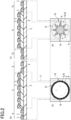
- Fig. 1 is a set of diagrams in which (b) is a cross-sectional view illustrating a three-dimensional display according to the present embodiment, (a) is a plan view illustrating a first region and a first contour region, and (c) is a plan view illustrating a second region and a second contour region.
- Fig. 2(a) is a cross-sectional view illustrating a detailed configuration example of the upper surface of the display shown in Fig. 1(b)
- Fig. 2(c) is a cross-sectional view illustrating a detailed configuration example of the lower surface of the display shown in Fig. 1(b)
- Fig. 2(b) is a plan view corresponding to Fig. 1(a)
- Fig. 2(d) is a plan view corresponding to Fig. 1(c) .
- Fig. 3 is a perspective view illustrating a state in which images are reconstructed apparently separated from the front and rear surfaces of an authentication medium.
- Fig. 3 shows a state in which a first reconstructed image 7a and a reconstructed image 11b derived from the second contour region respectively recorded in a first region 5 and a second contour region 10 are reconstructed on the front side, and a second reconstructed image 7b and a reconstructed image 11a derived from the first contour region respectively recorded in a second region 6 and a first contour region 9 are reconstructed on the rear side, in a three-dimensional display 4 according to the present embodiment.
- the three-dimensional display 4 has a configuration in which a plurality of first element cells 2 and a plurality of second element cells 3 are arranged on laminate sheets 1a and 1b.
- the laminate sheets 1a and 1b sandwich a laminate sheet 8 therebetween.
- Personal identification information such as biometric data is recorded in the first element cells 2.
- the second element cells 3 carry an authentication medium from which personal identification information is visible.
- the three-dimensional display 4 includes the first region 5 (see Fig. 1(a) that is a plan view corresponding to the upper surface of the display shown in Fig. 1(b) ) and the second region 6 (see Fig. 1(c) that is a plan view corresponding to the lower surface of the display shown in Fig. 1(b) ), which are formed by arranging the plurality of first element cells 2 and the plurality of second element cells 3.
- Respective phase shift structures are formed in the first element cells 2 and the second element cells 3.
- the three-dimensional display 4 can form unified patterns in respective edge portions as shown, for example, in Fig. 1(a) as a pattern of the front surface and in Fig. 1(c) as a pattern of the rear surface.
- images can be formed by removing part of the front and rear surfaces using a laser for demetallization.
- Fig. 2(a) is a cross-sectional view illustrating a detailed configuration example of the upper surface of the display shown in Fig. 1(b)
- Fig. 2(c) is a cross-sectional view illustrating a detailed configuration example of the lower surface of the display shown in Fig. 1(b) .
- the first element cells 2 and the second element cells 3 are arranged at a predetermined ratio in an interleaved manner in each of the first and second regions 5 and 6. This forms three-dimensional structures.
- the first and second regions 5 and 6 residing in the three-dimensional structures form coherent and unified three-dimensional images with groups of reconstruction points produced by reflected light from the phase shift structures, and these images are visible from different sides of the laminate sheet 8.
- the first region 5 is visible from above in Fig. 1(b)
- the second region 6 is visible from below in Fig. 1(b) .
- Being coherent can refer to a pattern in a region being able to enter a region having no pattern.
- being coherent can refer to a single motif being formed using front and rear patterns. The motif may be formed with letters, symbols, marks, or decorations.
- a first character e.g., face
- the first contour region 9 a first character (e.g., face), which is recorded in the first region 5, is surrounded by the first contour region 9.
- a second character (e.g., the sun), which is recorded in the second region 6, is surrounded by the second contour region 10.
- the first contour region 9 and the second contour region 10 are also provided with respective phase shift structures with a plurality of first and second element cells 2 and 3 arranged.
- the first element cells 2 and the second element cells 3 are arranged at a predetermined ratio in an interleaved manner in the first and second contour regions 9 and 10 to form three-dimensional structures.
- the first and second contour regions 9 and 10 are visible from different sides of the laminate sheet 8.
- the first contour region 9 is visible from the front side that is the upper side in the figure
- the second contour region 10 is visible from the rear side that is the lower side in the figure.
- the reconstructed image 11b derived from the second contour region is produced on the first surface (e.g., the front surface that is the upper side in the figure) side of the laminate sheet 8, at a position apparently separated from the laminate sheet 1a.
- the reconstructed image 11a is produced on the second surface (e.g., the rear surface that is the lower side in the figure) side of the laminate sheet 8, at a position apparently separated from the laminate sheet 1b.
- the first reconstructed image 7a and the reconstructed image 11b which is derived from the second contour region can be produced on the upper side in Fig.3 , being overlapped with each other. If only one of the first reconstructed image 7a and the reconstructed image 11b which is derived from the second contour region is produced, only poor three-dimensional effects can be achieved.
- the three-dimensional display 4 can produce the first reconstructed image 7a and the reconstructed image 11b which is derived from the second contour region being overlapped with each other, and therefore, the observer can feel an enhanced sense of depth.
- Part of the plane configured by the point groups of the first region 5 may be made parallel to part of the plane configured by the point groups of the second region 6. With this configuration, a multilayered composite image can be displayed.
- the second reconstructed image 7b and the reconstructed image 11a which is derived from the first contour region can be produced on the lower side in Fig.3 , being overlapped with each other. If only one of the second reconstructed image 7b and the reconstructed image 11a which is derived from the first contour region is produced, only poor three-dimensional effects can be achieved.
- the three-dimensional display 4 can produce the second reconstructed image 7b and the reconstructed image 11a which is derived from the first contour region, being overlapped with each other, and therefore, the observer can feel an enhanced sense of depth.
- Part of the plane configured by the point groups of the first contour region 9 may be made parallel to part of the plane configured by the point groups of the second contour region 10. With this configuration, a multilayered reconstructed image can be displayed.
- the first region 5 producing the first reconstructed image 7a can be arranged adjacent to the second region 6 which is configured by a diffraction grating that diffracts light with different pitches and azimuth angles in specific directions.
- the first region 5 may include a plurality of phase angle recording regions.
- the second region 6 may include a plurality of phase angle recording regions in which either or both of the pitches and azimuth angles are different between the regions. The phase angle recording region will be described later referring to Fig. 10 .
- the three-dimensional display 4 includes contour portions 20 including alignment markers 19, using which, the first contour region 9 is arranged adjacently to the second contour region 10 configured by a diffraction grating that diffracts light with different pitches and azimuth angles in specific directions.
- the first contour region 9 may also include a phase angle recording region described later.
- the second contour region 10 may include phase angle recording regions, described later, in which either or both of the pitches and azimuth angles are different between the regions.
- the areas of the first region 5 and the first contour region 9 can be made equal to or larger than those of the second region 6 and the second contour region 10.
- the first region 5 and the first contour region 9 may be arranged adjacent to the second region 6 and the second contour region 10 with a predetermined gap therebetween.
- luminance of the reconstructed images 7a, 7b, 11a and 11b may become dim depending on the area of the phase angle recording region described later. Accordingly, luminance can be adjusted by changing the areas of the first element cells 2 and the second element cells 3 in the first region 5, the first contour region 9, the second region 6, and the second contour region 10.
- the first element cells 2 and the second element cells 3 can be individually arranged with appropriate intervals therebetween, i.e., can be arranged away from each other via spacers, e.g., can be arranged being interleaved with each other at a predetermined ratio, to provide intervals with which the observer can simultaneously visually recognize them.
- the predetermined ratio can refer to the ratio between the first element cells 2 and the second element cells 3 in a unit area of calculated element sections described later.
- the first element cells 2 may be the same in size as the second element cells 3.
- the first element cells 2 may be the same in shape as the second element cells 3.
- the size of the first and second element cells 2 and 3 can be 5 ⁇ m or more and 150 ⁇ m or less. This size can be the length of the short side of each of the first and second element cells 2 and 3. Alternatively, this size can be the length of the short side of the rectangle circumscribing each of the first and second element cells 2 and 3.
- Fig. 1A(a) is a cross-sectional view illustrating the three-dimensional display 4 shown in Fig. 1(b) covered with single- or multi-layer reflective layers 14.
- Fig. 2A(a) is a cross-sectional view corresponding to Figs. 2(a) and 2(c) , in which the first and second element cells 2 and 3 shown in Figs. 2(a) and 2(c) are covered with single- or multi-layer reflective layers 14.
- Fig. 3A is a perspective view illustrating a positional relationship between the reconstructed images 7a, 7b, 11a and 11b shown in Fig. 3 .
- a first distance Z1 indicates a distance from a first surface (e.g., the upper surface in the figure) of the laminate sheet 1a to the first reconstructed image 7a.
- a second distance Z2 indicates a distance from a second surface (e.g., the lower surface in the figure) of the laminate sheet 1b to the second reconstructed image 7b.
- a third distance Z3 indicates a distance from the second surface (e.g., the lower surface in the figure) of the laminate sheet 1b to the reconstructed image 11a derived from the first contour region.
- a fourth distance Z4 indicates a distance from the first surface (e.g., the upper surface in the figure) of the laminate sheet 1a to the reconstructed image 11b derived from the second contour region.
- relations Z1 ⁇ Z2 and Z4 ⁇ Z3 are established.
- Fig. 4 is a diagram illustrating reconstructed images reversed in position from those in the authentication medium 100 shown in Fig. 3 .
- a first reconstructed image 7a and a reconstructed image 11b which is derived from the second contour region are formed on the lower side in the figure, at a position apparently separated from the laminate sheet 1a, and a second reconstructed image 7b and a reconstructed image 11a which is derived from the first contour region are formed on the upper side in the figure, at a position apparently separated from the laminate sheet 1b.
- Fig. 4A is a perspective view illustrating a positional relationship between the reconstructed images 7a, 7b, 11a and 11b shown in Fig. 4 .
- Figs. 3 and 4 indicate that the first and second reconstructed images 7a and 7b recorded as structures having a phase shift function in the first and second regions 5 and 6 can be observed under illumination light.
- illumination can produce the first and second reconstructed images 7a and 7b which are recorded as structures having a phase shift function in the phase angle recording region described later.
- the first reconstructed image 7a, the second reconstructed image 7b, the reconstructed image 11a derived from the first contour region, and the reconstructed image 11b derived from the second contour region are each configured by a plurality of reconstruction points.
- the first reconstructed image 7a, the second reconstructed image 7b, the reconstructed image 11a derived from the first contour region, and the reconstructed image 11b derived from the second contour region are displayed as groups of reconstruction points.
- the first reconstructed image 7a represents a face
- the second reconstructed image 7b represents the sun.
- the first and second reconstructed images 7a and 7b may be different images.
- the first and second reconstructed images 7a and 7b may be the same or different in size.
- the ratio of the convexity area between the first and second reconstructed images 7a and 7b may be 1:2 or more and 2:1 or less.
- the size of the first reconstructed image 7a may be smaller than the size of the second reconstructed image 7b.
- the ratio of the convexity area between the first and second reconstructed images 7a and 7b may be 1:10 or more and less than 1:2.
- the first reconstructed image 7a is produced facing the observer, i.e., produced on the front side, and the second reconstructed image 7b is produced on the rear side relative to the observer.
- Fig. 4 shows the state on the rear surface, where the expression is the opposite of that in Fig. 3 described above.
- the reconstructed image 11a derived from the first contour region is shown in white on a black background, while the reconstructed image 11b derived from the second contour region is shown in black on a white background.
- the reconstructed image 11a derived from the first contour region may be different from the reconstructed image 11b derived from the second contour region.
- the reconstructed image 11a derived from the first contour region and the reconstructed image 11b derived from the second contour region may have the same size.
- the ratio of the convexity area between the reconstructed images 11a and 11b derived from the first and second contour regions may be 1:2 or more and 2:1 or less.
- the size of the reconstructed image 11a derived from the first contour region may be smaller than the size of the reconstructed image 11b derived from the second contour region.
- the ratio of the convexity area between the reconstructed images 11a and 11b derived from the first and second contour regions may be 1:10 or more and less than 1:2.
- the reconstructed image 11b derived from the second contour region is produced facing the observer, i.e., produced on the front side, and the reconstructed image 11a derived from the first contour region is produced on the rear side relative to the observer.
- Fig. 4 shows the state on the rear surface, where the expression is the opposite of that in Fig. 3 described above.
- the first reconstructed image 7a, the second reconstructed image 7b, the reconstructed image 11a derived from the first contour region, and the reconstructed image 11b derived from the second contour region, which are planar reconstructed images, are produced in space, appearing at positions separated from the three-dimensional display 4.
- the structures having a phase shift function can produce the planar reconstructed images 7a, 7b, 11a and 11b in space.
- the reconstructed images 7a, 7b, 11a and 11b can have curved surfaces.
- the stereoscopic effects perceived by the observer when observing the images become greater in proportion to the reproduction distances to the reconstructed images, i.e., the distances between the centers of the reconstructed images 7a, 7b, 11a and 11b and the front surface of the three-dimensional display 4 (distances Z1, Z2, Z3 and Z4 described above).
- the three-dimensional display 4 produces the reconstructed images 7a, 7b, 11a and 11b in the space on the front side and in the space on the rear side. This can increase the stereoscopic effects, while suppressing blurring of the reconstructed images 7a, 7b, 11a and 11b.
- Figs. 3A and 4A both show examples in each of which the reconstruction distance Z1 from the three-dimensional display 4 to the first reconstructed image 7a is different from the reconstruction distance Z2 from the three-dimensional display 4 to the reconstructed image 7b; however, Fig. 4A shows an example in which the front and rear sides of the three-dimensional display 4 are reversed to produce the two reconstructed images 7a and 7b in the opposite direction to Fig. 3A .
- Figs. 3A and 4A both show examples in each of which the reconstruction distance Z3 from the three-dimensional display 4 to the reconstructed image 11a derived from the first contour region is different from the reconstruction distance Z4 from the three-dimensional display 4 to the reconstructed image 11b derived from the second contour region.
- Fig. 3A shows an example in which the reconstructed images 11a and 11b derived from the first and second contour regions are produced on different sides sandwiching the three-dimensional display 4
- Fig. 4A shows an example in which the front and rear sides of the three-dimensional display 4 shown in Fig. 3A are reversed to produce the reconstructed images 11a and 11b derived from the first and second contour regions in the opposite direction to Fig. 3A .
- the reconstruction distance Z1 from the three-dimensional display 4 to the first reconstructed image 7a is different from the reconstruction distance Z2 from the three-dimensional display 4 to the second reconstructed image 7b, satisfying a relation Z2 ⁇ Z1.
- the reconstruction distance Z3 from the three-dimensional display 4 to the reconstructed image 11a derived from the first contour region is different from the reconstruction distance Z4 from the three-dimensional display 4 to the reconstructed image 11b derived from the second contour region, satisfying a relation Z4 ⁇ Z3.
- Fig. 4A shows a state in which the three-dimensional display 4 shown in Fig. 3A is viewed from the rear side, and effects that are reversed from Fig. 3A are obtained as an expression, satisfying relations Z1 ⁇ Z2 and Z3 ⁇ Z4.
- the three-dimensional display 4 may be configured such that the first and second reconstructed images 7a and 7b are both produced on the front side, or conversely, both produced on the rear side.
- the first reconstructed image 7a and the reconstructed image 11a which is derived from the first contour region are clearly visible even when the reconstruction distances Z2 and Z3 or the viewing angle become large.
- the second reconstructed image 7b and the reconstructed image 11b which is derived from the second contour region are clearly visible. Therefore, the contrast between the first and second reconstructed images 7a and 7b can provide a visual sense of depth.
- the structure having a phase shift function of reconstructing reconstruction points can be achieved by calculating phases in the structure having a phase shift function from the optical distances and wavelengths of the individual reconstruction points using the CGH technique, and by recording the structure having a phase shift function of shifting phases of incident light according to the calculated phases, in the phase angle recording region (described later) of the first region 5, the first contour region 9, the second region 6, or the second contour region 10.
- a structure having a phase shift function can also be recorded as a relief structure or can be recorded as modulations of refractive indices, in the phase angle recording region described later.
- the recording is performed as follows. First, a resist plate that is a glass plate to which an electron beam resist is applied is exposed to an electron beam with a dose corresponding to the amount of phase shift, and the resist plate is developed to form asperities corresponding to the amount of phase shift. Next, a metal layer is deposited on the asperities formed on the resist plate to prepare a master plate. Next, a nickel shim on which the asperities are duplicated is electroformed from the master plate. The duplicated shim is embossed on a film including a carrier to which a resin is applied, to record the relief structure in the resin. In this way, the structure having a phase shift function recorded as a relief structure is excellent for mass production.
- the resin on which the relief structure is embossed may be a thermoplastic resin, thermosetting resin, or a composite of these resins.
- the composite of a thermoplastic resin and a thermosetting resin is able to record phases therein in the form of a highly accurate relief structure, and therefore, reconstruction points can be recorded with a high density.
- the three-dimensional display 4, in which the relief structure is recorded can easily be destroyed if heated and peeled off from the adherend for the purpose of tampering, and thus can have high tamper resistance.
- a relief structure including the first region 5, first contour region 9, second region 6, and second contour region 10 is formed on one side.
- two single-sided relief structures including the first region 5, first contour region 9, second region 6, and second contour region 10 are formed, with alignment markers 19 provided on blank areas of the laminate sheets, these two relief structures are bonded together while being aligned using the markers 19, and the blank areas including the markers are cut off or the markers are removed by demetallization to leave them as patterns.
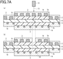
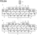
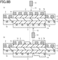
- Figs. 5, 6 , 7A , 7B , 8A and 8B show a method of forming the three-dimensional structure of the three-dimensional display 4.
- high intensity laser light 13a is applied to one side or both sides of the three-dimensional display 4 from a laser irradiation device 12a.
- the first element cells 2 and/or the second element cells 3 forming the three-dimensional structure of a resin are melted and the single- or multi-layer reflective layer 14 on the laminate sheet 1 is evaporated, thereby partly demetallizing the hologram foil on the front side with a laser, as shown in Figs. 5(b) , 7A(b) and 7B(b) .
- an infrared laser having a wavelength of 1,064 nm, YVO/YAG laser, fiber laser, or CO 2 laser (gas laser) having a wavelength of 10,600 nm can be used.
- the material of the reflective layer 14 may be metal or a metal compound, or silicon oxide.
- the metal compound may be a metal oxide, metal sulfide, or metal fluoride. These metal compounds are less likely to be chemically altered and can retain the reconstructed images recorded in the recording regions for a long time.
- the metal sulfide may be zinc sulfide.
- the metal oxide may be titanium dioxide.
- the metal fluoride may be magnesium fluoride.
- the metal may be aluminum, silver, tin, nickel, chromium, elemental gold, or an alloy thereof. In particular, aluminum, which forms a passive layer, has high durability and thus can retain the reconstructed images recorded in the recording regions for a long time.
- low intensity laser light 13b may be applied to one side or both sides from a laser irradiation device 12b.
- a laser irradiation device 12b may be applied to one side or both sides from a laser irradiation device 12b.
- only the single- or multi-layer reflective layer 14 can be entirely or partly removed by forming it with a material having a different wavelength absorption, leaving the first element cells 2 and/or the second element cells 3.
- the material having a different wavelength absorption may be a metal compound.
- the metal compound may be zinc sulfide, alumina, or titanium oxide. These metal compounds are less likely to be chemically altered and can retain the reconstructed images stored in the storage regions for a long time.
- the first and second element cells 2 and 3 forming the three-dimensional structures may be formed of resins that can be deformed by a laser, so that the shapes of the reconstructed images can be changed as desired or the effects of the reconstructed images can be reduced or increased.
- Demetallization using a laser can thus form a transparent window portion 23, and by transferring three-dimensional hologram foils to the front and rear sides of the window portion, cards which are resistant to counterfeiting can be produced.
- An example in which this is applied to a passport will be described.
- Fig. 9 is a diagram illustrating an example of a passport formed by transferring three-dimensional hologram foils to the front and rear sides of transparent window portions.
- three-dimensional hologram foils are transferred to the front and rear sides of the transparent window portions, which correspond to the transparent window portion 23 shown in Fig. 7A(b) , to form a first facial image 41 and a second facial image 42.
- the tempering can be detected from discrepancies with the second facial image 42 formed in the transparent window portion. Also, counterfeit products can be visually detected from the deviation between the three-dimensional patterns on the front and rear sides.
- the following description relates to a method of recording the phases calculated using a CGH technique in the phase angle recording region of the first region 5, the first contour region 9, the second region 6, or the second contour region 10.
- Fig. 10 is a diagram illustrating a phase angle recording region for recording phases calculated using a CGH technique.
- the three-dimensional display 4 has a recording surface on the laminate sheet 8.
- the recording surface is provided with pixels which are grouped, as described in PTL 7, into calculated element sections 15, a phase angle recording region 16, and a phase angle non-recording region 17.
- the reconstructed image is formed of a plurality of reconstruction points.
- the reconstruction points are at positions apparently separated from the pixel plane in the Z direction preferably by 5 mm or more and 25 mm or less.
- the viewing angle direction is the X direction or the Y direction.
- the viewing angle ⁇ from the reconstruction point is defined by the following Formula (1). ⁇ ⁇ A / m
- the wavelength ⁇ of light may be specifically 555 nm, which corresponds to the maximum human visual sensitivity to visible light.
- the arrangement interval d may be the distance between the centers of the unit blocks.
- the arrangement interval d of the unit blocks may be 10 nm or more and 200 nm or less.
- the viewing angle ⁇ which is determined by the range in the X direction when the pixel plane is viewed from the reconstruction point of interest, is 1/2 of the angle 2 ⁇ formed by a minimum value Xmin in the X direction, the reconstruction point of interest, and a maximum value Xmax in the X direction.
- the X direction and the Y direction respectively correspond to the X and Y coordinate axes of Euclidean coordinates where one direction in which the pixel plane extends is defined to be an X direction and the direction orthogonal to the X direction is defined to be a Y direction.
- the viewing angle ⁇ when the viewing angle direction is the Y direction is similarly defined.
- the viewing angle ⁇ which is determined by the range in the Y direction when the relief surface is viewed from the reconstruction point of interest, is 1/2 of the angle 2 ⁇ formed by a minimum value Ymin in the Y direction, the reconstruction point of interest, and a maximum value Ymax in the Y direction.
- the arrangement interval d between the unit blocks corresponds to an arrangement interval dx between the unit blocks in the X direction when the viewing angle direction is the X direction, and corresponds to an arrangement interval dy between the first element cells 2 and second element cells 3 in the Y direction when the viewing angle direction is the Y direction.
- the calculated element sections 15 each generally have a square or rectangular shape.
- the calculated element sections 15 may have a polygonal shape other than quadrangle, or may have a circular or elliptical shape. In addition to squares and rectangles, hexagons in particular can be appropriately used as the polygonal shape.
- the minimum value (lower limit) in the X direction of the calculated element section 15 may be defined by Xmin
- the maximum value (upper limit) in the X direction of the calculated element section 15 may be defined by Xmax.
- the minimum value in the Y direction of the calculated element section 15 may be defined by Ymin
- the maximum value in the Y direction of the calculated element section 15 may be defined by Ymax.
- each unit block has a square or rectangular shape
- the square or rectangle may actually have rounded corners.
- Each unit block may be merged with the adjacent unit blocks. In this case, even when each unit block has a rounded square shape, the merged unit blocks do not necessarily have a rounded square shape but may have a deformed shape; however, even when the shape is changed by the merge, the optical effects may remain unchanged.
- the unit blocks are preferably arranged in an orderly manner.
- the orderly arrangement may be an arrangement in which the unit blocks are arranged at intervals within a predetermined range or an arrangement in which they are arranged at regular intervals.
- a typical orderly arrangement may be a square or hexagonal arrangement.
- the viewing angle ⁇ is less than A. If light passes through this phase component and is diffracted, theoretically no diffraction beyond A may occur. Accordingly, if computational hologram calculation is performed, the calculation range may be limited to the viewing angle ⁇ as an upper limit. By limiting the calculation range, the calculation time can be shortened. If the calculation is performed for the range beyond the viewing angle ⁇ , the calculation may only be performed for diffraction that does not theoretically exist, and therefore, the results may only contribute as noise. In this regard, since the above calculation is not performed for the range beyond the viewing angle ⁇ , noise will not be superimposed on the reconstruction points when producing a reconstructed image thereon.
- the phase angle recording region 16 and the phase angle non-recording region contain a plurality of unit blocks.
- the unit blocks included in an overlapping region where they overlap with the calculated element sections 15 are targeted for computational phase angle calculation based on the phase components, and the calculated phase angles are recorded in the respective unit blocks included in the overlapping region.
- the calculated element sections 15 are defined in this way on the pixel plane according to the viewing angles ⁇ .
- the calculated element sections 15 correspond one-to-one to the reconstruction points of the reconstructed image, and the phase component of light from each of the reconstruction points is calculated. Since there are multiple reconstruction points, there also are multiple calculated element sections 15 whose number is the same as that of the reconstruction points, and the phase component of light from each of the reconstruction points is calculated for the corresponding one of the multiple calculated element sections 15.
- the phase angle recording region 16 is a region in which the phase angles calculated based on the phase components can be recorded.
- the phase angle non-recording region 17 is a region in which the phase angles are not recorded, and is a mirror surface according to an example.
- phase angles are recorded in the overlapping region, where the calculated element sections 15 overlap with the phase angle recording region 16, for the respective calculated element sections 15 therein.
- the phase angle non-recording region 17 can record therein information other than the phase angles, such as properties of light scattering, reflection, and diffraction.
- Fig. 11 is a set of diagrams in which (a) is a cross-sectional view illustrating a laminate 30 before embedding the three-dimensional display 4 and (b) is a cross-sectional view illustrating the laminate 30 after embedding the three-dimensional display 4.
- the overall thickness may be in the range of 0.18 mm or more and 0.84 mm or less according, for example, to JIS X6311 and JIS X6301 (ISO/IEC7810).
- the laminate 30 is formed by sequentially laminating, from the upper side in the figure, a transparent protective layer 31 that is a transparent outer layer substrate, a phase modulation layer 32 that receives and modulates illumination light, an imprinted layer 33 that is a transparent intermediate substrate developing colors when exposed to laser light, a core layer 34 that is a core substrate, an imprinted layer 33, a phase modulation layer 32, and a transparent protective layer 31.
- a transparent protective layer 31 that is a transparent outer layer substrate
- a phase modulation layer 32 that receives and modulates illumination light
- an imprinted layer 33 that is a transparent intermediate substrate developing colors when exposed to laser light
- a core layer 34 that is a core substrate
- an imprinted layer 33 that is a phase modulation layer 32
- a transparent protective layer 31 The first region 5 and the second region 6 of the three-dimensional display 4 are visible from outside the laminate 30.
- a laminate 30 in which a three-dimensional display 4 is embedded can be provided, as shown in Fig. 11(b) , by embedding the three-dimensional display 4 in an embedding portion 35 which is a transparent non-printed portion as a part of the core layer 34.
- the three-dimensional display 4 can also be formed on a carrier, not shown.
- the three-dimensional display 4 on the carrier, not shown can be attached to an adherend, not shown, by hot-stamping it via an adhesion region 18 shown in Figs. 1B and 2B .
- Figs. 1B and 2B are cross-sectional views each illustrating an example of a positional relationship between laminate sheets and the adhesion region.
- the laminate sheet on which the three-dimensional display 4 is arranged can be attached, for example, to an adherend, e.g., printed notes, printed pages, and printed cards, via the adhesion region 18 shown in Figs. 1B and 2B .
- the adhesion region 18 can also be attached to an adherend by hot stamping.
- the authentication medium 100 is a card.
- the card can be an ID card, license card, or game card.
- the ID card can be a national ID card, foreigner residence card, or tax payment card.
- a booklet can be a passport.
- the carrier may be a plastic film.
- the plastic film may be made of PET (polyethylene terephthalate), PEN (polyethylene naphthalate), or PP (polypropylene).
- the plastic film may include a coating layer formed by applying a resin.
- the phase modulation layers 32 may be multilayers. Each phase modulation layer 32 may have a configuration in which an embossing layer, a reflective layer, and a mask layer are sequentially laminated. The reflective layer and the mask layer may be omitted.
- the material of the transparent protective layers 31 may be a thermoplastic polymer.
- the material of the embossing layer may be a curable polymer.
- the material of the reflective layer may be an inorganic material.
- the transparent protective layer 31 and the embossing layer can be formed by coating.
- the reflective layer can be formed into a single- or multi-layer by deposition.
- the deposition may be physical deposition or chemical deposition.
- the physical deposition may be vacuum vapor deposition or sputtering.
- the mask layer can be formed by printing an ink.
- the printing may be offset printing, gravure printing, or screen printing.
- the ink may be an oil-based ink or water-based ink.
- the ink may be
- the embossing layer may be a single layer or a composite layer.
- the composite layer may be configured by a relief layer, an intermediate part, and an anchor layer.
- the relief layer may be made of a curable polymer.
- the anchor layer may be made of a thermosetting polymer.
- the intermediate layer may be a mixture.
- the transparent protective layer 31 may be made of a material that is a mixture of a resin and a lubricant.
- the resin may be a thermoplastic resin. Examples of the resin include acrylic resins, polyester resins, polyamide resins, and cellulose resins.
- the lubricant may be a wax such as polyethylene powder, paraffin wax, silicone wax, carnauba wax, or the like. These may be applied to a substrate layer using a known coating method such as a gravure printing method or microgravure method to provide a release layer.
- the release layer may have a thickness in the range of 0.5 ⁇ m or more and 5 ⁇ m or less.
- the material of the embossing layer may be polyacrylate, polyurethane acrylate, or polyacrylic acrylate.
- the material of the relief layer may be polyacrylate, polyurethane acrylate, or polyacrylic acrylate.
- the material of the intermediate part may be a mixture of polyacrylate and polyurethane acrylate.
- the material of the anchor layer may be polyurethane acrylate.
- the transparent protective layer 31, the phase modulation layer 32, the imprinted layer 33, and the core layer 34 in which the three-dimensional display 4 is embedded in the embedding portion 35 are laminated in this order by applying heat and pressure, and the laminate is integrated by thermocompression bonding to form a laminate 30 as shown in Fig. 11(b) .
- the laminate 30 can be used for cards, tags, or booklet pages. Thus, an authentication medium with a security label can be formed.
- a reflective scattering layer may be provided.
- functional inks whose colors change according to the illumination angles or the observation angles may be used.
- optically variable inks, color shift inks, or pearl inks for example, can be used.
- the following description relates to recording using the arrangement of the first region 5, first contour region 9, second region 6, and second contour region 10.
- the first region 5 can record personal identification data including biometric information.
- the face of the ID card holder can be produced as a color image expressed by two or more colors, i.e., can be produced as a first reconstructed image 7a by allowing the individual calculated element sections 15 to have gradation values of the respective colors.
- the second region 6 can record different data of the personal identification data including the biometric information recorded in the first region 5.
- hash information or the like related to the ID card holder stored in the first region 5 can be produced as a second reconstructed image 7b by allowing the individual calculated element sections 15 to have gradation values binarized based on the first region 5.
- the first contour region 9 has gradation values of the respective colors for each of the calculated element sections 15.
- the second contour region 10 has gradation values binarized based on the first contour region 9 for each of the calculated element sections 15.
- the first and second contour regions 9 and 10 can record characters of personal identification information including the biometric information related to the first and second regions 5 and 6.
- the hash information or the like related to the ID card holder recorded in the first and second regions 5 and 6 can be produced as a reconstructed image 11a derived from the first contour region and a reconstructed image 11b derived from the second contour region, by which aesthetic effects can be enhanced.
- the first and second contour regions 9 and 10 can be used for preventing counterfeiting of the first and second regions 5 and 6.
- the first region 5 may be combined with the first contour region 9 and the element cells on these regions may be arranged overlapping the two regions, so that a counterfeit product made by peeling off the original product can produce a reconstructed image from which a counterfeiting can be detected.
- a transparent polycarbonate resin sheet (thickness: 100 ⁇ m) was used as a material for the transparent protective layer 31
- a transparent polycarbonate resin sheet including a phase shift structure (thickness: 100 ⁇ m) was used as a material for the phase modulation layer 32
- a laser coloring polycarbonate resin sheet (thickness: 100 ⁇ m) was used as a material for the imprinted layer 33
- a white polycarbonate resin sheet (thickness: 200 ⁇ m) was used as a material for the core layer 34.
- a three-dimensional display 4 formed on a laminate sheet was partly hot-stamped and attached to the imprinted layer 33 and, after that, the transparent protective layer 31, the phase modulation layer 32, the imprinted layer 33, and the core layer 34 in which the three-dimensional display 4 was arranged in the embedding portion 35 thereof were laminated together in this order, followed by heating and pressing with a 180-degree plate and further followed by cooling. After that, the laminate was punched into a shape of 85 mm ⁇ 54 mm to obtain a card.
- the observer can feel a sense of depth from the reconstructed image of the facial motif and the reconstructed image of the motif of the sun which appear distanced from each other by 4 mm.
- the reconstructed image 7a of the face produced at a distance of 2 mm from the front surface was visible on the front side of the three-dimensional display 4; however, under lighting of a point light source, the reconstructed image 7b of the sun produced at a distance of 2 mm from the rear surface was visible on the front side of the three-dimensional display 4.
- a resist plate on a surface of which a relief structure was formed as asperities by electron-beam lithography was formed as a master plate, an electrically conductive film was deposited on the surface of the master plate, and a shim duplicating the relief structure was prepared by electroforming.
- a peelable transparent protective layer 31 was formed on a PET film carrier by coating, and an embossing layer was formed by applying a precursor to the transparent protective layer 31 with a dry thickness of 3 ⁇ m. Then, while being heated and UV-irradiated, the shim having electroformed asperities on the surface thereof was pressed against the surface of the embossing layer for embossment, thereby forming asperities as a relief structure on the embossing layer. After that, an aluminum reflective layer was formed by vacuum vapor deposition on the surface of the embossing layer on which the relief structure was formed. Furthermore, an adhesive was applied to the reflective layer to form an adhesive layer. These materials used for coating may be diluted with a solvent.
Landscapes
- Physics & Mathematics (AREA)
- General Physics & Mathematics (AREA)
- Engineering & Computer Science (AREA)
- Manufacturing & Machinery (AREA)
- Optics & Photonics (AREA)
- Health & Medical Sciences (AREA)
- Electromagnetism (AREA)
- General Health & Medical Sciences (AREA)
- Toxicology (AREA)
- Computer Security & Cryptography (AREA)
- Credit Cards Or The Like (AREA)
Claims (18)
- Affichage tridimensionnel (4) formé en agençant des premières cellules élémentaires (2) dans lesquelles des informations d'identification personnelle sont enregistrées, et des deuxièmes cellules élémentaires (3) portant un support d'authentification depuis lequel les informations d'identification personnelle sont visibles, dans lequel les premières et deuxièmes cellules élémentaires sont agencées sur une feuille stratifiée, dans lequell'affichage inclut une première région (5) et une deuxième région (6) formées en agençant une pluralité des premières cellules élémentaires (2) et une pluralité des deuxièmes cellules élémentaires (3) ;les premières cellules élémentaires (2) et les deuxièmes cellules élémentaires (3) forment respectivement des structures de déphasage ;dans la première région (5) et dans la deuxième région (6), les premières cellules élémentaires (2) et les deuxièmes cellules élémentaires (3) sont agencées de manière entrelacée selon un rapport prédéterminé pour former des structures tridimensionnelles respectives ;la première région (5) et la deuxième région (6) résidant dans les structures tridimensionnelles forment des images tridimensionnelles cohérentes et unifiées avec des groupes de points de reconstruction produits par la lumière réfléchie provenant des structures de déphasage ;une première image reconstruite (7a) est produite sur un premier côté de la feuille stratifiée, à une position apparemment séparée de la feuille stratifiée, en raison de la structure de déphasage formée par les premières cellules élémentaires (2) ; etune deuxième image reconstruite (7b) est produite sur un deuxième côté de la feuille stratifiée, à une position apparemment séparée de la feuille stratifiée, en raison de la structure de déphasage formée par les deuxièmes cellules élémentaires (3).
- Affichage tridimensionnel (4) dans lequel une première région de contour (9) entourant un premier caractère enregistré, et une deuxième région de contour (10) entourant un deuxième caractère enregistré sont agencées sur une feuille stratifiée, dans lequelune pluralité de premières cellules élémentaires dans lesquelles sont enregistrées des informations d'identification personnelle et une pluralité de deuxièmes cellules élémentaires (3) portant un support d'authentification depuis lequel les informations d'identification personnelle sont visibles sont agencées dans la première région de contour (9) et dans la deuxième région de contour (10) pour former des structures de déphasage respectives ;dans la première région de contour (9) et dans la deuxième région de contour (10), les premières cellules élémentaires (2) et les deuxièmes cellules élémentaires (3) sont agencées de manière entrelacée selon un rapport prédéterminé pour former des structures tridimensionnelles respectives ;la première région de contour (9) et la deuxième région de contour (10) sont respectivement visibles depuis les premier et deuxième côtés de la feuille stratifiée ;une image reconstruite (11b) dérivée de la deuxième région de contour (10) est produite sur le premier côté de la feuille stratifiée, à une position apparemment séparée de la feuille stratifiée, en raison de la structure de déphasage formée par les premières cellules élémentaires (2) ; etune image reconstruite (11a) dérivée de la première région de contour (9) est produite sur le deuxième côté de la feuille stratifiée, à une position apparemment séparée de la feuille stratifiée, en raison de la structure de déphasage formée par les deuxièmes cellules élémentaires (3).
- Affichage tridimensionnel, dans lequelun premier repère (19) est disposé sur la feuille stratifiée sur laquelle est agencé l'affichage tridimensionnel selon la revendication 1 ;un deuxième repère (19) est disposé sur la feuille stratifiée sur laquelle est agencé l'affichage tridimensionnel selon la revendication 2 ; etl'affichage tridimensionnel selon la revendication 1 et l'affichage tridimensionnel selon la revendication 2 sont combinés l'un avec l'autre en amenant les deux feuilles stratifiées en alignement en utilisant le premier repère et le deuxième repère.
- Affichage tridimensionnel selon la revendication 3, dans lequel l'affichage tridimensionnel selon la revendication 1 et l'affichage tridimensionnel selon la revendication 2 se chevauchent et sont combinés l'un avec l'autre.
- Affichage tridimensionnel selon la revendication 1, dans lequel une relation Z1<Z2 est établie entre une première distance Z1 qui est une distance allant du premier côté à la première image reconstruite (7a) et une deuxième distance Z2 qui est une distance allant du deuxième côté à la deuxième image reconstruite (7b).
- Affichage tridimensionnel selon la revendication 1 ou la revendication 4, dans lequel une relation Z1>Z2 est établie entre une première distance Z1 qui est une distance allant du premier côté à la première image reconstruite (7a) et une deuxième distance Z2 qui est une distance allant du deuxième côté à la deuxième image reconstruite (7b).
- Affichage tridimensionnel selon la revendication 2, dans lequel une relation Z4<Z3 est établie entre une troisième distance Z3 qui est une distance allant du deuxième côté à l'image reconstruite (11a) dérivée de la première région de contour et une quatrième distance Z4 qui est une distance allant du premier côté à l'image reconstruite (11b) dérivée de la deuxième région de contour.
- Affichage tridimensionnel selon la revendication 2 ou la revendication 4, dans lequel une relation Z4>Z3 est établie entre une troisième distance Z3 qui est une distance allant du deuxième côté à l'image reconstruite (11a) dérivée de la première région de contour et une quatrième distance Z4 qui est une distance allant du premier côté à l'image reconstruite (11b) dérivée de la deuxième région de contour.
- Affichage tridimensionnel selon la revendication 1, dans lequella feuille stratifiée inclut une surface d'enregistrement, la surface d'enregistrement incluant,des sections élémentaires calculées correspondant une à une à des points de reconstruction de la première image reconstruite (7a) et de la deuxième image reconstruite (7b), et soumises à un calcul de composante de phase pour la lumière provenant des points de reconstruction individuels,une région d'enregistrement d'angle de phase dans laquelle des angles de phase calculés sur la base des composantes de phase peuvent être enregistrés, etune région de non-enregistrement d'angle de phase dans laquelle les angles de phase ne sont pas enregistrés ; etles angles de phase sont enregistrés dans une région de chevauchement où les sections élémentaires calculées chevauchent la région d'enregistrement d'angle de phase.
- Affichage tridimensionnel selon la revendication 2, dans lequella feuille stratifiée inclut une surface d'enregistrement, la surface d'enregistrement incluant,des sections élémentaires calculées correspondant une à une à des points de reconstruction de l'image reconstruite (11a) dérivée de la première région de contour et de l'image reconstruite (11b) dérivée de la deuxième région de contour, et soumises à un calcul de composante de phase pour la lumière provenant des points de reconstruction individuels,une région d'enregistrement d'angle de phase dans laquelle des angles de phase calculés sur la base des composantes de phase peuvent être enregistrés, etune région de non-enregistrement d'angle de phase dans laquelle les angles de phase ne sont pas enregistrés ; etles angles de phase sont enregistrés dans une région de chevauchement où les sections élémentaires calculées chevauchent la région d'enregistrement d'angle de phase.
- Affichage tridimensionnel selon la revendication 9 ou la revendication 10, dans lequelune pluralité des sections élémentaires calculées sont disposées ;une composante de phase de lumière provenant de chacun des points de reconstruction est calculée pour une section correspondante de la pluralité de sections élémentaires calculées ; etl'angle de phase calculé est enregistré dans la section correspondante des sections élémentaires calculées.
- Affichage tridimensionnel selon l'une quelconque des revendications 9 à 11, dans lequel des informations autres que les angles de phase sont enregistrées dans la région de non-enregistrement d'angle de phase.
- Affichage tridimensionnel selon la revendication 12, dans lequel
les informations autres que les angles de phase sont des informations incluant au moins l'une parmi la diffusion de lumière, la réflexion de lumière, et la diffraction de lumière. - Affichage tridimensionnel selon la revendication 9, dans lequella première région (5) inclut des valeurs de gradation en tant que données d'une image en couleur exprimée par deux couleurs ou plus, pour chacune des sections élémentaires calculées en termes des couleurs individuelles ; etla deuxième région (6) inclut des valeurs de gradation binarisées sur la base de la première région, pour chacune des sections élémentaires calculées.
- Affichage tridimensionnel selon la revendication 10, dans lequella première région de contour (9) inclut des valeurs de gradation en tant que données d'une image en couleur exprimée par deux couleurs ou plus, pour chacune des sections élémentaires calculées en termes des couleurs individuelles ; etla deuxième région de contour (10) inclut des valeurs de gradation binarisées sur la base de la première région de contour, pour chacune des sections élémentaires calculées.
- Support d'authentification (100) incluant un stratifié dans lequel sont stratifiés un substrat de couche externe transparent, un substrat de déphasage destiné à recevoir et à moduler la lumière d'éclairage, un substrat intermédiaire transparent développant des couleurs lorsqu'il est exposé à une lumière laser, et un substrat central, dans lequelau moins une partie du substrat central inclut une portion transparente non imprimée ; etl'affichage tridimensionnel selon l'une quelconque des revendications 1 à 15 est incorporé dans le stratifié.
- Support d'authentification selon la revendication 16, dans lequel la première région et la deuxième région de l'affichage tridimensionnel sont visibles depuis l'extérieur du stratifié.
- Procédé de formation de l'affichage tridimensionnel selon l'une quelconque des revendications 1 à 15, dans lequel la structure tridimensionnelle est formée par les premières cellules élémentaires et les deuxièmes cellules élémentaires qui sont traitées en appliquant de façon externe une lumière laser à l'affichage tridimensionnel pour former la structure tridimensionnelle.
Applications Claiming Priority (2)
| Application Number | Priority Date | Filing Date | Title |
|---|---|---|---|
| JP2021096554 | 2021-06-09 | ||
| PCT/JP2022/022990 WO2022260047A1 (fr) | 2021-06-09 | 2022-06-07 | Affichage 3d, authentificateur et procédé de formation |
Publications (3)
| Publication Number | Publication Date |
|---|---|
| EP4353487A1 EP4353487A1 (fr) | 2024-04-17 |
| EP4353487A4 EP4353487A4 (fr) | 2024-07-17 |
| EP4353487B1 true EP4353487B1 (fr) | 2025-06-25 |
Family
ID=84425098
Family Applications (1)
| Application Number | Title | Priority Date | Filing Date |
|---|---|---|---|
| EP22820226.3A Active EP4353487B1 (fr) | 2021-06-09 | 2022-06-07 | Affichage 3d, authentificateur et procédé de formation |
Country Status (5)
| Country | Link |
|---|---|
| US (1) | US12522013B2 (fr) |
| EP (1) | EP4353487B1 (fr) |
| JP (1) | JPWO2022260047A1 (fr) |
| KR (1) | KR20240019148A (fr) |
| WO (1) | WO2022260047A1 (fr) |
Families Citing this family (1)
| Publication number | Priority date | Publication date | Assignee | Title |
|---|---|---|---|---|
| EP3584091B1 (fr) * | 2017-02-16 | 2024-01-31 | Dai Nippon Printing Co., Ltd. | Page d'informations |
Family Cites Families (15)
| Publication number | Priority date | Publication date | Assignee | Title |
|---|---|---|---|---|
| JPH081538B2 (ja) * | 1986-05-31 | 1996-01-10 | 大日本印刷株式会社 | カード及びその情報読み取り方法 |
| JPH0467683A (ja) | 1990-07-09 | 1992-03-03 | Nippon Telegr & Teleph Corp <Ntt> | 速度変調型電界効果トランジスタ |
| JP3198324B2 (ja) | 1991-05-08 | 2001-08-13 | 大日本印刷株式会社 | 記録体及び記録体の記録方法 |
| JPH0667592A (ja) | 1992-08-24 | 1994-03-11 | Toppan Printing Co Ltd | 昇華転写画像用透明ホログラム転写箔 |
| US7336422B2 (en) * | 2000-02-22 | 2008-02-26 | 3M Innovative Properties Company | Sheeting with composite image that floats |
| JP4677683B2 (ja) | 2001-05-15 | 2011-04-27 | 凸版印刷株式会社 | 表示体およびそれからの情報再生方法 |
| DE102006016139A1 (de) | 2006-04-06 | 2007-10-18 | Ovd Kinegram Ag | Mehrschichtkörper mit Volumen-Hologramm |
| JP5589563B2 (ja) | 2010-05-31 | 2014-09-17 | 凸版印刷株式会社 | 立体画像表示体 |
| JP5712623B2 (ja) * | 2011-01-14 | 2015-05-07 | 凸版印刷株式会社 | 偽造防止媒体及び印刷物 |
| GB201301790D0 (en) * | 2013-02-01 | 2013-03-20 | Rue De Int Ltd | Security devices and methods of manufacture thereof |
| KR20170020725A (ko) | 2015-07-29 | 2017-02-24 | 주식회사 하이딥 | 압력 전극이 형성된 디스플레이 모듈을 포함하는 터치 입력 장치 및 압력 전극 형성 방법 |
| KR102437351B1 (ko) * | 2016-06-03 | 2022-08-30 | 도판 인사츠 가부시키가이샤 | 광학 필름 및 표시체 |
| EP3815920B1 (fr) * | 2018-06-29 | 2024-11-06 | Toppan Printing Co., Ltd. | Corps d'authentification, procédé de fabrication de corps d'authentification, procédé de lecture de corps d'authentification et procédé de vérification de corps d'authentification |
| AU2019363013B2 (en) * | 2018-09-24 | 2023-06-22 | Ovd Kinegram Ag | Optically variable element, security document, method for producing an optically variable element, method for producing a security document |
| JP2021157079A (ja) * | 2020-03-27 | 2021-10-07 | 凸版印刷株式会社 | セキュリティラベル |
-
2022
- 2022-06-07 JP JP2023527877A patent/JPWO2022260047A1/ja active Pending
- 2022-06-07 KR KR1020237043153A patent/KR20240019148A/ko active Pending
- 2022-06-07 EP EP22820226.3A patent/EP4353487B1/fr active Active
- 2022-06-07 WO PCT/JP2022/022990 patent/WO2022260047A1/fr not_active Ceased
-
2023
- 2023-12-07 US US18/532,534 patent/US12522013B2/en active Active
Also Published As
| Publication number | Publication date |
|---|---|
| KR20240019148A (ko) | 2024-02-14 |
| EP4353487A4 (fr) | 2024-07-17 |
| US12522013B2 (en) | 2026-01-13 |
| US20240100874A1 (en) | 2024-03-28 |
| EP4353487A1 (fr) | 2024-04-17 |
| WO2022260047A1 (fr) | 2022-12-15 |
| JPWO2022260047A1 (fr) | 2022-12-15 |
Similar Documents
| Publication | Publication Date | Title |
|---|---|---|
| EP2951029B1 (fr) | Dispositif de sécurité et procédés de fabrication de ceux-ci | |
| CA2687992C (fr) | Corps multicouche | |
| US9902187B2 (en) | Security devices and methods of manufacture thereof | |
| US10252562B2 (en) | Security elements and methods of their manufacture | |
| CN1589205B (zh) | 用于防伪纸和有价文件的防伪元件 | |
| US7654579B2 (en) | Object of value comprising a moiré pattern | |
| CN100429083C (zh) | 具有局部透明元件的光学变化元件 | |
| GB2549481B (en) | Security devices and methods of manufacture thereof | |
| EP4006780B1 (fr) | Structure optique et procédé de production de structure optique | |
| JP2024109700A (ja) | セキュリティラベル | |
| US12522013B2 (en) | Three-dimensional display, authentication medium, and formation method | |
| JP2024066184A (ja) | 情報記録媒体、その加工方法、ならびに情報記録媒体に記録された情報の観察方法 | |
| JP2024115960A (ja) | 表示体および表示体の加工方法 | |
| HK1071871B (en) | Security element for security papers and valuable documents |
Legal Events
| Date | Code | Title | Description |
|---|---|---|---|
| STAA | Information on the status of an ep patent application or granted ep patent |
Free format text: STATUS: THE INTERNATIONAL PUBLICATION HAS BEEN MADE |
|
| PUAI | Public reference made under article 153(3) epc to a published international application that has entered the european phase |
Free format text: ORIGINAL CODE: 0009012 |
|
| STAA | Information on the status of an ep patent application or granted ep patent |
Free format text: STATUS: REQUEST FOR EXAMINATION WAS MADE |
|
| 17P | Request for examination filed |
Effective date: 20231129 |
|
| AK | Designated contracting states |
Kind code of ref document: A1 Designated state(s): AL AT BE BG CH CY CZ DE DK EE ES FI FR GB GR HR HU IE IS IT LI LT LU LV MC MK MT NL NO PL PT RO RS SE SI SK SM TR |
|
| A4 | Supplementary search report drawn up and despatched |
Effective date: 20240619 |
|
| RIC1 | Information provided on ipc code assigned before grant |
Ipc: G03H 1/02 20060101ALI20240613BHEP Ipc: G02B 5/18 20060101ALI20240613BHEP Ipc: B42D 25/328 20140101AFI20240613BHEP |
|
| DAV | Request for validation of the european patent (deleted) | ||
| DAX | Request for extension of the european patent (deleted) | ||
| GRAP | Despatch of communication of intention to grant a patent |
Free format text: ORIGINAL CODE: EPIDOSNIGR1 |
|
| STAA | Information on the status of an ep patent application or granted ep patent |
Free format text: STATUS: GRANT OF PATENT IS INTENDED |
|
| INTG | Intention to grant announced |
Effective date: 20250218 |
|
| GRAS | Grant fee paid |
Free format text: ORIGINAL CODE: EPIDOSNIGR3 |
|
| GRAA | (expected) grant |
Free format text: ORIGINAL CODE: 0009210 |
|
| STAA | Information on the status of an ep patent application or granted ep patent |
Free format text: STATUS: THE PATENT HAS BEEN GRANTED |
|
| AK | Designated contracting states |
Kind code of ref document: B1 Designated state(s): AL AT BE BG CH CY CZ DE DK EE ES FI FR GB GR HR HU IE IS IT LI LT LU LV MC MK MT NL NO PL PT RO RS SE SI SK SM TR |
|
| REG | Reference to a national code |
Ref country code: GB Ref legal event code: FG4D |
|
| REG | Reference to a national code |
Ref country code: CH Ref legal event code: EP |
|
| REG | Reference to a national code |
Ref country code: CH Ref legal event code: EP |
|
| REG | Reference to a national code |
Ref country code: IE Ref legal event code: FG4D |
|
| REG | Reference to a national code |
Ref country code: DE Ref legal event code: R096 Ref document number: 602022016602 Country of ref document: DE |
|
| PG25 | Lapsed in a contracting state [announced via postgrant information from national office to epo] |
Ref country code: FI Free format text: LAPSE BECAUSE OF FAILURE TO SUBMIT A TRANSLATION OF THE DESCRIPTION OR TO PAY THE FEE WITHIN THE PRESCRIBED TIME-LIMIT Effective date: 20250625 |
|
| REG | Reference to a national code |
Ref country code: LT Ref legal event code: MG9D |
|
| PG25 | Lapsed in a contracting state [announced via postgrant information from national office to epo] |
Ref country code: NO Free format text: LAPSE BECAUSE OF FAILURE TO SUBMIT A TRANSLATION OF THE DESCRIPTION OR TO PAY THE FEE WITHIN THE PRESCRIBED TIME-LIMIT Effective date: 20250925 Ref country code: GR Free format text: LAPSE BECAUSE OF FAILURE TO SUBMIT A TRANSLATION OF THE DESCRIPTION OR TO PAY THE FEE WITHIN THE PRESCRIBED TIME-LIMIT Effective date: 20250926 |
|
| PG25 | Lapsed in a contracting state [announced via postgrant information from national office to epo] |
Ref country code: BG Free format text: LAPSE BECAUSE OF FAILURE TO SUBMIT A TRANSLATION OF THE DESCRIPTION OR TO PAY THE FEE WITHIN THE PRESCRIBED TIME-LIMIT Effective date: 20250625 |
|
| PG25 | Lapsed in a contracting state [announced via postgrant information from national office to epo] |
Ref country code: HR Free format text: LAPSE BECAUSE OF FAILURE TO SUBMIT A TRANSLATION OF THE DESCRIPTION OR TO PAY THE FEE WITHIN THE PRESCRIBED TIME-LIMIT Effective date: 20250625 |
|
| PG25 | Lapsed in a contracting state [announced via postgrant information from national office to epo] |
Ref country code: RS Free format text: LAPSE BECAUSE OF FAILURE TO SUBMIT A TRANSLATION OF THE DESCRIPTION OR TO PAY THE FEE WITHIN THE PRESCRIBED TIME-LIMIT Effective date: 20250925 |
|
| PG25 | Lapsed in a contracting state [announced via postgrant information from national office to epo] |
Ref country code: LV Free format text: LAPSE BECAUSE OF FAILURE TO SUBMIT A TRANSLATION OF THE DESCRIPTION OR TO PAY THE FEE WITHIN THE PRESCRIBED TIME-LIMIT Effective date: 20250625 |
|
| REG | Reference to a national code |
Ref country code: NL Ref legal event code: MP Effective date: 20250625 |
|
| PG25 | Lapsed in a contracting state [announced via postgrant information from national office to epo] |
Ref country code: NL Free format text: LAPSE BECAUSE OF FAILURE TO SUBMIT A TRANSLATION OF THE DESCRIPTION OR TO PAY THE FEE WITHIN THE PRESCRIBED TIME-LIMIT Effective date: 20250625 |
|
| PG25 | Lapsed in a contracting state [announced via postgrant information from national office to epo] |
Ref country code: PT Free format text: LAPSE BECAUSE OF FAILURE TO SUBMIT A TRANSLATION OF THE DESCRIPTION OR TO PAY THE FEE WITHIN THE PRESCRIBED TIME-LIMIT Effective date: 20251027 |
|
| REG | Reference to a national code |
Ref country code: AT Ref legal event code: MK05 Ref document number: 1806105 Country of ref document: AT Kind code of ref document: T Effective date: 20250625 |
|
| PG25 | Lapsed in a contracting state [announced via postgrant information from national office to epo] |
Ref country code: IS Free format text: LAPSE BECAUSE OF FAILURE TO SUBMIT A TRANSLATION OF THE DESCRIPTION OR TO PAY THE FEE WITHIN THE PRESCRIBED TIME-LIMIT Effective date: 20251025 |
|
| PG25 | Lapsed in a contracting state [announced via postgrant information from national office to epo] |
Ref country code: AT Free format text: LAPSE BECAUSE OF FAILURE TO SUBMIT A TRANSLATION OF THE DESCRIPTION OR TO PAY THE FEE WITHIN THE PRESCRIBED TIME-LIMIT Effective date: 20250625 Ref country code: SM Free format text: LAPSE BECAUSE OF FAILURE TO SUBMIT A TRANSLATION OF THE DESCRIPTION OR TO PAY THE FEE WITHIN THE PRESCRIBED TIME-LIMIT Effective date: 20250625 |
|
| PG25 | Lapsed in a contracting state [announced via postgrant information from national office to epo] |
Ref country code: CZ Free format text: LAPSE BECAUSE OF FAILURE TO SUBMIT A TRANSLATION OF THE DESCRIPTION OR TO PAY THE FEE WITHIN THE PRESCRIBED TIME-LIMIT Effective date: 20250625 |
|
| PG25 | Lapsed in a contracting state [announced via postgrant information from national office to epo] |
Ref country code: PL Free format text: LAPSE BECAUSE OF FAILURE TO SUBMIT A TRANSLATION OF THE DESCRIPTION OR TO PAY THE FEE WITHIN THE PRESCRIBED TIME-LIMIT Effective date: 20250625 |
|
| PG25 | Lapsed in a contracting state [announced via postgrant information from national office to epo] |
Ref country code: EE Free format text: LAPSE BECAUSE OF FAILURE TO SUBMIT A TRANSLATION OF THE DESCRIPTION OR TO PAY THE FEE WITHIN THE PRESCRIBED TIME-LIMIT Effective date: 20250625 |
|
| PG25 | Lapsed in a contracting state [announced via postgrant information from national office to epo] |
Ref country code: SK Free format text: LAPSE BECAUSE OF FAILURE TO SUBMIT A TRANSLATION OF THE DESCRIPTION OR TO PAY THE FEE WITHIN THE PRESCRIBED TIME-LIMIT Effective date: 20250625 |
|
| PG25 | Lapsed in a contracting state [announced via postgrant information from national office to epo] |
Ref country code: ES Free format text: LAPSE BECAUSE OF FAILURE TO SUBMIT A TRANSLATION OF THE DESCRIPTION OR TO PAY THE FEE WITHIN THE PRESCRIBED TIME-LIMIT Effective date: 20250625 |
|
| PG25 | Lapsed in a contracting state [announced via postgrant information from national office to epo] |
Ref country code: DK Free format text: LAPSE BECAUSE OF FAILURE TO SUBMIT A TRANSLATION OF THE DESCRIPTION OR TO PAY THE FEE WITHIN THE PRESCRIBED TIME-LIMIT Effective date: 20250625 |
|
| PG25 | Lapsed in a contracting state [announced via postgrant information from national office to epo] |
Ref country code: IT Free format text: LAPSE BECAUSE OF FAILURE TO SUBMIT A TRANSLATION OF THE DESCRIPTION OR TO PAY THE FEE WITHIN THE PRESCRIBED TIME-LIMIT Effective date: 20250625 |
|
| PLBE | No opposition filed within time limit |
Free format text: ORIGINAL CODE: 0009261 |
|
| STAA | Information on the status of an ep patent application or granted ep patent |
Free format text: STATUS: NO OPPOSITION FILED WITHIN TIME LIMIT |