EP4353652A1 - Procédé d'assemblage modulaire d'au moins un module de section longitudinale d'un dispositif de voie de circulation à assemblage modulaire, dispositif de voie de circulation - Google Patents
Procédé d'assemblage modulaire d'au moins un module de section longitudinale d'un dispositif de voie de circulation à assemblage modulaire, dispositif de voie de circulation Download PDFInfo
- Publication number
- EP4353652A1 EP4353652A1 EP22200508.4A EP22200508A EP4353652A1 EP 4353652 A1 EP4353652 A1 EP 4353652A1 EP 22200508 A EP22200508 A EP 22200508A EP 4353652 A1 EP4353652 A1 EP 4353652A1
- Authority
- EP
- European Patent Office
- Prior art keywords
- module
- modules
- longitudinal section
- section
- head
- Prior art date
- Legal status (The legal status is an assumption and is not a legal conclusion. Google has not performed a legal analysis and makes no representation as to the accuracy of the status listed.)
- Pending
Links
Images



Classifications
-
- B—PERFORMING OPERATIONS; TRANSPORTING
- B66—HOISTING; LIFTING; HAULING
- B66B—ELEVATORS; ESCALATORS OR MOVING WALKWAYS
- B66B23/00—Component parts of escalators or moving walkways
Definitions
- the present invention relates to methods for the module-specific assembly of at least one longitudinal section module of a modularly assembled guideway device before connecting/marrying at least two longitudinal section modules of the guideway device to one another, wherein the guideway device is provided in a modular configuration with at least three separately/independently created longitudinal section modules comprising two head modules and at least one intermediate module, in particular in the manufacture of escalators. Furthermore, the present invention relates to a guideway device, in particular an escalator, with a corresponding modular structure. The present invention also relates in particular to the handling of support structure components on/along the value chain up to the completed support structure of the entire guideway device.
- the present invention also relates to the use of certain machine tools or systems on the one hand and certain assembly aids on the other hand, each to facilitate and optimize the individual steps of this module-specific procedure.
- the invention relates to a device and a method according to the preamble of the respective independent claim.
- the components to be assembled in the head areas of the escalator must usually be installed in an inclined position of the head areas, especially if the supporting structure of the escalator has already been created and is present over the entire intended length of the escalator and the angular alignment of an intermediate section between the head modules relative to the head modules is already predefined, i.e. if the intended gradient/inclination of the escalator has already been structurally implemented.
- a large part of the assembly/installation measures usually take place in this state, with corresponding requirements for cranes, support arms or similar assembly aids designed for large loads.
- Examples include the publications EP 3 426 588 B1 and EP 3 426 589 B1 which each describe a device and a method for producing a passenger transport system based on several joining steps. Furthermore, the EP 3 724 118 B1 which indicate measures intended to facilitate order picking or other measures preparatory to production or the production process, particularly in the case of escalators.
- the task is to provide a method and a corresponding device or structural design with which escalators or general guideway devices can be manufactured in the simplest possible way. It is also the task to design a concept for the structural design of guideway devices and a mounting/assembly process dependent on this in such a way that the guideway devices can be manufactured with the highest possible standardization and efficiency on the one hand and the best possible accessibility on the other.
- the guideway device can be provided or is provided in a modular configuration with at least three separately/independently created longitudinal section modules (or module-specific support structures of the respective longitudinal section module) comprising two head modules and at least one intermediate module, wherein the respective head module has a platform section that is to be arranged at least approximately horizontally for the intended operation and an inclined section connected thereto, wherein at least one of the head modules can be arranged or is arranged for the modular (module-individual, module-specific) assembly (in particular relative to a floor/subsurface of a machine hall) before the longitudinal section modules are connected to one another in such a way that its platform section is aligned horizontally, in particular with the inclined section already in alignment with the intended adjacent intermediate module.
- This allows good accessibility and provides a very lean process.
- the manufacturing/assembly process in such a way that at least the head sections that are intended to be horizontally aligned and preferably also the intermediate module remain accessible in a horizontal orientation for as long as possible until a late stage of the value creation process, in particular for manufacturing and assembly measures.
- This also promotes an easy-to-control process in conjunction with at least one intermediate module that is at least approximately horizontally aligned.
- the main assemblies arranged/to be arranged in the end areas usually have to be assembled in an inclined position, because the escalator is usually not provided in modules, but in this phase of the production process already rests as a whole over the entire length of the device/supporting structure in the manner/shape of an elongated Z letter on the floor or in a corresponding suspension/support, so that at least the head sections or the individual longitudinal sections are all aligned at an angle to the floor plane, and their front ends are therefore only easily accessible in an inclined direction.
- the present invention provides a concept that also makes it possible, after the respective supporting structure of the individual longitudinal sections has been created, to equip further To facilitate installation components and optionally also to standardize them, e.g. with regard to the installation direction or position.
- the present invention is based primarily on the concept of providing escalator devices and similarly constructed guideway devices in modules in individual segmented longitudinal sections, in particular in a phase of the construction process up to the completed section-by-section support structure, and then assembling the individual modules individually module by module or assembling or installing the components required for each module, whereby this concept can be implemented according to the invention not only for the intermediate module in a horizontal orientation but also in a simple manner for the end sections of the head modules, which in particular also ensures the advantage of providing/keeping the head modules for this assembly process with their platform section in a horizontal orientation and advantageous position.
- the upper and lower head modules of the escalator/guideway device are created independently of one another as separate modules (at least the respective support structure) and then further components are assembled module-specifically, and in this respect the entire device is prepared module by module for final assembly.
- This modular approach also allows, for example, the head modules to be positioned in an advantageous horizontal alignment and (relative) position in the area of or in connection with heavy main assemblies (such as shafts and drive units).
- Avoiding an inclined position, particularly of the respective platform section also provides the following advantages, particularly for assembly: time savings, particularly thanks to easier alignment work, improved accessibility, constant predefined position/alignment of main assemblies regardless of the intended inclination/inclination of the inclined section (thereby also making internal logistics easier in particular), and thus no need for complex adaptation of any equipment and tools for calibration to the gradient, inclination and/or with regard to an (absolute) conveying height of the respective guideway device.
- This can also ensure improved occupational safety, particularly in terms of avoiding work at dangerous heights and reducing the risk of crushing and entrapment (especially since heavy assemblies can no longer slip off so easily).
- the general term "travel device” refers primarily to escalator devices (in particular including moving walkways) and moving walkway devices (the latter in particular in a stepless design in at least approximately flat alignment or with a negligible gradient) as well as related passenger transport devices with a continuously rotating transport device.
- the guideway device includes, for example, segments or units that form the transport device, in particular steps or pallets, which are connected to driven chains or similar drive means and guided in guide rails.
- the guide rails as well as a chain (or a similarly acting traction means) and other components of the guideway device are held, for example, within load-bearing constructions or support structures that extend essentially laterally in the axial direction, which are usually made up of two side wall units that are opposite one another and are connected to one another via crossbeams and optionally also a floor unit, and can also include struts arranged in a lattice-like manner.
- the term "guideway device” also refers in particular to modularly constructed guideway devices that are modularly constructed from several longitudinal sections or longitudinal section modules, each with an individual or longitudinal section-specific support structure, and can be assembled/mounted in modules.
- the guideway devices described here can also comprise moving walkway devices, i.e. guideway devices that are at least approximately horizontally aligned without steps but with individual guideway elements that are not intended to overcome an incline but form a largely flat route; in this respect, a reference to a bend or an inclined section is to be understood here to mean that the corresponding section is described largely independently of any incline actually realized.
- the general term "assembly” or the more specific term “final assembly” generally refers to the assembly of the entire/complete support structure of the guideway device, which can also include all of the intended longitudinal section modules (two head modules and at least one intermediate module); this final assembly is also described here as a pairwise modular connection/marriage of the support structures of at least two longitudinal section modules, or at least comprising this connection step.
- the term "assembly” can also include preparatory steps such as picking/providing/keeping components ready for a respective longitudinal section or module or for the entire guideway device; according to the present disclosure, the invention primarily relates to steps and aspects that are downstream of picking, i.e. do not include picking in the narrower sense.
- module refers specifically to the assembly or assembly of only certain individual modules or their components in the corresponding module, for example, specifically in the case of a head module, where, for example, components of a/the drive are installed in the upper head module, or guides, rails, cladding parts or components of the balustrade are (pre-)assembled in just one of the modules.
- the assembly of components can take place at least partially in a phase in which the modules are still handled separately from one another, or in a phase in which the modules are already married to one another; this variation option affects, for example, the individual steps/pallets; in this respect, too, the use of the term "assembly" is not to be understood as restricting certain phases of the process of creating the complete guideway device or its supporting structure.
- longitudinal section module is to be understood in the sense of the present disclosure generally as a load-bearing longitudinal module of the guideway device, i.e. as a module that forms a longitudinal or length section of the guideway device and provides the support structure for it (i.e. a component of the guideway device in the corresponding length range that is at least structurally complete).
- This term therefore includes the terms “head module” and “intermediate module”.
- head module refers to a module arranged at one of the ends of the guideway device and refers optionally to both types of head modules (upper and lower head module, also referred to as upper part and lower part); in this respect, this term can equally refer to the module at the upper or lower end of the guideway device.
- head modules In guideway devices designed as escalators, head modules usually extend over one or the angle of inclination of the guideway device and thus span the bend or the transition from the inclined longitudinal section to the respective horizontal longitudinal section.
- the term "platform section” refers to the section of the respective head module that is aligned at least approximately in a horizontal plane in the intended arrangement; in this respect, when describing the arrangement/alignment of the respective head module, reference is also made to the alignment of this platform section (or its main extension plane), in particular if or when the absolute length of the platform section is greater than the absolute length of the inclined section.
- the "connecting inclined section” (also referred to in the specialist literature as a stub) is to be understood in particular as the inclined/inclined section intended for connecting/marrying with another longitudinal section module, and this inclined section can be more or less long depending on the function of the respective head module; this means that the individual modules are intended to be connected to one another in the area of a/the intended inclined longitudinal section; if several intermediate modules are provided, a Connecting/marrying the intermediate modules with each other or first connecting the respective head module and intermediate module.
- the general term "longitudinal section” can refer either to a longitudinal section module or a specific longitudinal section, particularly of the head module (i.e. platform section or inclined section).
- longitudinal section compared to the term “longitudinal section module” refers, unless further specified, equally to the head sections and the at least one intermediate section and is used according to the present disclosure when modularity or a modular design or a strictly modular process is not necessarily required or can also be varied or modified according to the invention, or when reference is made to a process or a device-related state which is still prior to the intended modular construction of the individual modules, e.g. relating to connecting individual longitudinal sections of a head module to form the entire head module.
- individual longitudinal sections are referred to without explicitly referring to them as longitudinal section modules, not only the individual modules but also longitudinal sections of an individual module can be affected, in particular a platform section (e.g. first longitudinal section) and an inclined section (e.g. second longitudinal section) of a head module, for which two sections a specific connection process can be provided (in particular in the area of the bend);
- a platform section e.g. first longitudinal section
- an inclined section e.g. second longitudinal section
- individual longitudinal sections of a module can be positioned relative to one another by means of form-fitting contours, e.g. in connection with a material-locking connection of these longitudinal sections to create the entire supporting structure of the respective module.
- A/the support structure of a/the guideway device or of a/the respective module can essentially be formed by opposing side wall units and cross members (also referred to as crossbars) connecting them, wherein a/the side wall unit is formed by at least one side wall and in particular by an upper flange and/or a lower flange; the modular manufacturing process described here can also include the connection of a floor unit to the side wall units; however, it has been shown that such a floor unit does not necessarily have to fulfill a support function, but is designed, for example, with regard to the function of collecting oil from a/the drive and, if necessary, draining it, or is designed in an optimized manner with regard to a cover and/or accessibility from below to the support structure or the guideway device; in this respect, the floor unit is to be understood as an optional structural unit, which can also be functionally provided separately from the support structure, but which can optionally can also take on an additional supporting load-bearing function if desired in individual cases.
- side wall refers to a side structure which, for example, runs flat in only one side plane at least in sections, but is alternatively or additionally formed and/or reinforced at least in sections by profiles, struts or supports extending beyond one/the side plane.
- the side wall is made up of structural elements or structural sections which, as flat structural sections, absorb forces in several directions and/or, as rod-shaped or strut-like structural parts/sections/elements, absorb the respective forces only along the longitudinal extension specified by the orientation (tension or compression); such components of the load-bearing structure can also be referred to by the English term “truss member” or "truss section”, whereby according to the present disclosure, a truss-like structure does not necessarily have to be present; the term “truss” can nevertheless be considered appropriate here, because the side wall usually has a truss-like structure at least in sections, i.e.
- the side wall is thus designed, for example, as a closed surface, as a pure framework or as a structure with parts (or sections) of closed surfaces and parts with a framework structure.
- the load-bearing structural parts/sections of the side wall are made of flat material, in particular sheet metal, e.g. structurally flat sections or stiffening (in particular) curved L- or U-profile sections in the area of welded connections to other structural parts/elements/sections.
- a “side wall unit” comprises the side wall described here and belts associated with this side wall, in particular an upper belt and a lower belt, wherein the belts can be formed integrally with the side wall, integrated or separate from one another. These belts are alternatively also referred to as bands.
- the respective side wall/unit can also be understood as a side wall/unit provided in modules, depending on the reference to a/the respective phase of the manufacturing process of the individual modules or the entire guideway device.
- the term side wall unit can refer to the entire side structure comprising the upper and lower chords, and the term side wall can refer to the side structure arranged between the upper and lower chords.
- chords refer to structural parts/elements or corresponding load-bearing sections extending longitudinally in the area of an upper edge or a lower edge of the side wall for receiving Loads in the longitudinal direction of the guideway device, in particular bending loads, which primarily lead to tensile stresses in the lower chord and to compressive stresses in the upper chord.
- the chords are preferably designed as profiles or profile sections, in particular as L-profiles, U-profiles or hollow profiles and thus have a favorable area moment of inertia for absorbing the bending loads.
- the chords therefore stiffen the support structure and form external corner points, with the chords and/or the side walls optionally serving to attach further components of the guideway device.
- the chords can also be designed as components separate from the side wall; however, at least some of the chords are preferably formed in one piece with the side wall, for example by bending the side wall.
- the upper chord is particularly preferably designed as a hollow profile with four walls, with two walls being formed by the L-shaped side wall, which is made of flat material in this area, and two further walls being formed by a flat material component that is also L-shaped and separate from the side wall.
- the lower chord is preferably designed in a similar manner as a hollow profile with four walls, with two walls being formed by the L-shaped side wall made from flat material in this area and two walls being formed by the base unit, which is also L-shaped and made from flat material in this area.
- the components forming the walls are preferably welded together.
- the upper chord and/or the lower chord can also be provided entirely in one piece with the side wall or entirely separately from the side wall (particularly in the sense of a process variation).
- Structurally loadable is understood to mean a point or component of the supporting structure that is temporarily loadable to absorb at least the forces resulting from the dead mass of the guideway device or the corresponding module, e.g. in connection with individual assembly steps. This term is used, for example, in relation to the reference points described here.
- load-bearing is understood to mean a component or a part (section) of the supporting structure which is designed to withstand the prevailing static and dynamic forces and moments, even under continuous loading over several years, when the guideway device is used as intended.
- connecting means in the sense of the present disclosure is to be understood as a screw connection or a rivet connection, in particular a so-called locking ring bolt connection, particularly in connection with a connection between modules.
- the person skilled in the art can specify whether such a preferred rivet connection or Locking ring bolt connection is to be replaced in individual cases or at individual connection points by, for example, a screw connection.
- the rivet connection or locking ring bolt connection preferably comprises at least one visual inspection marking, in particular one which lifts off the material.
- the present invention is also based in particular on the concept that at least a significant portion of a side wall, an upper flange, a lower flange and/or the entire side wall unit, which portion defines the overall shape, is made of flat material, in particular sheet metal, with at least one reference point preferably being defined on the flat material.
- a side wall, an upper flange, a lower flange and/or the entire side wall unit, which portion defines the overall shape is made of flat material, in particular sheet metal, with at least one reference point preferably being defined on the flat material.
- the invention particularly preferably includes the teaching of introducing further references, in particular corresponding recesses (in the sense of additional component-specific assembly reference points) on the flat material in addition to the at least one reference point arranged in particular in the corresponding side wall during the course of the same processing method, on which further components can be arranged directly and thus in a defined position relative to the at least one (master) reference point with high accuracy.
- references or reference recesses are also introduced in particular in areas of the flat material which can be subjected to further processing steps, in particular bending processes, following laser cutting, whereby the referencing concept described here can also be implemented for multi-dimensional positioning in space with respect to at least two or all three spatial directions.
- the invention further includes the teaching that the reference point is defined by, for example, a circular recess or by its center, to which further positioning devices (i.e. assembly aids such as, for example, side support units) for positioning individual longitudinal sections or components can be clamped, for example.
- the respective component with the reference point or the entire module or even the entire guideway device is lifted at at least one reference point or supported around a reference axis formed by several reference points, e.g.
- an upper chord or a lower chord can also be formed from a profile, with corresponding processing methods, in particular tube laser cutting methods, for forming a reference point and/or further references also being available for profiles.
- components refers to components to be installed in the respective guideway devices or in the respective modules of the guideway device, e.g. relating to electrics, drive, guidance or the like. If a load-bearing function is to be fulfilled by a structural component, in particular for the intended continuous load, the term “load-bearing components” or structural parts/elements/sections is used in connection with the supporting structure.
- Both head modules of the guideway device can be arranged in such a way that the respective platform section is/will be aligned horizontally, whereby the respective platform section is/will remain accessible in the horizontal direction for the respective module-by-module (module-individual) assembly.
- This also provides advantages in terms of simultaneous assembly on several modules, e.g. arranged one behind the other in a line.
- the respective head module is/will therefore be provided with the platform section and a connecting inclined section (i.e. with a supporting structure already created that extends over the angled transition area), whereby the corresponding inclined section is/will be aligned at an angle by aligning the platform section horizontally.
- the respective longitudinal section module for forming a/the support structure of the longitudinal section module is created independently of the other longitudinal section modules by at least one of the following steps: laser cutting of at least one side wall (unit), in particular two-dimensional laser cutting, arranging the two side walls/side wall units of the longitudinal section module in parallel alignment with each other, in particular above a base unit of the longitudinal section module, and arranging cross struts of the longitudinal section module between the side walls and connecting these load-bearing components to each other to form the load-bearing support structure of the corresponding Longitudinal section module.
- the respective head module for forming a/the support structure of the head module is created independently of the other longitudinal section modules by at least one of the following steps, each relating to the platform section and the inclined section: laser cutting of two side walls or side wall units, in particular two-dimensional laser cutting, arranging the two side wall units in parallel alignment with one another, in particular above a base unit of the head module, and arranging cross struts of the head module between the side walls and connecting these load-bearing components to one another; wherein before or after the arranging/connecting of the cross struts, the platform section and the inclined section are connected to form the load-bearing support structure of the corresponding side wall unit of the corresponding head module, in particular using form-fitting contours for the relative positioning of the sections relative to one another in connection with an at least partially material-locking connection.
- a respective side wall unit is created over the entire longitudinal extent of the head module before the side wall units are connected to one another using the cross bars/struts.
- the expert can implement process-related deviations or extensions on this basis. In this case, optimization can also be carried out in a simple manner with regard to the achievable accuracy, in particular with reference to the form-fitting contours mentioned here.
- the module-specific assembly (or module-specific assembly, e.g. of drive components) of at least one of the head modules is carried out separately from a module-specific assembly of the other longitudinal section modules, wherein the platform section of this head module is/remains aligned horizontally and is supported against the ground by at least one support and movement device, wherein this head module is/remains optionally displaceable relative to the ground by means of the support and movement device and is/remains accessible in the horizontal direction regardless of a specific inclination (angle of inclination ⁇ ) of the connecting inclined section.
- this also facilitates the implementation of a process-related/production-technically advantageous sequence for several modules in combination with one another.
- a first head module is assembled separately and individually, regardless of the arrangement/orientation of a/the second head module and/or the at least one intermediate module, in particular with regard to at least one of the following components: shafts, drive unit, further drive train components, optionally also stages.
- the modular concept described here also makes it possible, for example, to decide on a module-specific basis in which state of the respective module or at which point in the manufacturing process the integration of a respective component, e.g. the stages, makes sense; this also results in new variation options.
- both a first of the head modules with its platform section in a horizontal orientation and a second of the head modules are assembled with its platform section in a horizontal orientation, e.g. one after the other/sequentially within the same relative or absolute assembly position or simultaneously at opposite ends of a longitudinal section module connection arrangement (or a modular assembly line for the module and final assembly of guideway devices) comprising the at least three longitudinal section modules in a linear or axially aligned arrangement/alignment one behind the other relative to one another.
- a longitudinal section module connection arrangement or a modular assembly line for the module and final assembly of guideway devices
- both the head modules with their respective platform sections in an at least approximately horizontal orientation and the at least one intermediate module in an at least approximately horizontal orientation are provided separately from one another for assembly. This provides the advantage of good standardizable accessibility in the horizontal direction for all modules and is therefore completely independent of the angle of inclination of the device that is individually specified in the individual case.
- the platform section of at least one of the head modules is arranged horizontally in the area of or in alignment with massive/heavy main assemblies such as at least one shaft and/or further drive units of the guideway device, for modular assembly of these main assemblies in horizontal alignment of the corresponding platform section regardless of the specific inclination (angle of inclination ⁇ ) of the connecting inclined section.
- massive/heavy main assemblies such as at least one shaft and/or further drive units of the guideway device
- devices and tools provided for module-by-module assembly can be arranged or are arranged/aligned accordingly for the assembly process regardless of the inclination (angle of inclination ⁇ ) of the connecting inclined section of the respective head module, namely by being arranged/aligned in a predefined manner in coordination with a/the horizontal alignment of the corresponding platform section, in particular in an assembly line aligned axially along a predefined assembly direction for connecting the support structures of the respective modules or the entire guideway device.
- This allows the unification or at least internal standardization of the manufacturing processes to be implemented even further.
- the at least one head module and the at least one intermediate module are then connected/married, in particular by means of form-fitting/non-positively mountable sheet metal connections (final assembly of the guideway device in particular without a material bond, purely non-positive/positive) and/or at least partially by means of form-fitting contours for the relative positioning of the modules relative to one another by form-fitting coupling and subsequent connection.
- this also facilitates handling and relative positioning of modules relative to one another even without complex assembly aids, for example also largely decoupled from complex welding/joining production lines or corresponding welding robotics.
- the side wall units of the head modules can also have been created beforehand by form-fitting coupling and subsequent connection, in particular each in one plane with primarily two-dimensional processing (accessibility essentially from a direction orthogonal to the processing plane/working plane).
- the modules are then connected/married in pairs, optionally a purely force-locking/positive connection or at least partially also a material connection, in particular with a constant axial alignment along a predefined assembly axis, in particular in/on/along one and the same assembly line, in particular with the respective module in suspension or support in at least two reference points arranged in the side walls of the module or corresponding reference recesses preferably laser-cut (in particular circular reference recesses).
- modules are thus married in pairs in a state in which they are already equipped with other components, ie the respective support structure already accommodates other components, e.g. drive components or at least one support or guide rail.
- the individual modules are connected purely in a force-fitting/positive-fitting manner.
- the individual longitudinal section modules are each aligned axially in alignment relative to one another by means of at least two support and movement devices for providing at least two supports per longitudinal section module and positioned relative to one another along an assembly line/axis for connecting in pairs, in particular in an arrangement/support/suspension of the respective longitudinal section module in reference points or around a reference axis in the side wall units, in particular using a side stop for the lateral positioning of the support and movement devices, in particular without the need for guide rails embedded in the floor.
- This increases the process flexibility/variability even further and can also make handling of the individual modules for module-specific measures even easier.
- arranging and aligning can also be carried out essentially via the reference points that can be provided integrally by means of the support structure of the respective module.
- a guideway device in modular construction with at least three separate longitudinal section modules to be connected to one another (to be married to one another to form a complete guideway device), consisting of two head modules and at least one intermediate module, wherein the respective longitudinal section module has a (load-bearing) support structure, in particular in a truss construction, wherein the longitudinal section modules are designed to be connected to one another in pairs (in particular each by means of at least one load-bearing module connection designed to connect the support structures of at least two longitudinal section modules to one another), in particular at the front end, wherein the respective head module has a platform section and a connecting inclined section and with the platform section and the connecting inclined section in the connected state in a predefined orientation relative to one another according to the intended inclination angle of the guideway device can be provided independently (detached) from at least one intermediate module, wherein the (respective) platform section can be arranged in
- connection or coupling of paired longitudinal section modules takes place, for example, by means of sheet metal connections which contact neighboring modules and axially overlap (in particular in the case of lateral surface contact/application), and/or by means of form-fitting contours for coupling and referenced positioning of paired longitudinal section modules.
- the (respective) platform section can be supported in a horizontal orientation against the ground independently of the at least one intermediate module, in particular at support points and/or reference points designed for this purpose on the platform section in at least two longitudinal positions. This promotes the most precise horizontal alignment possible in the desired plane.
- the support points can coincide with the reference points described elsewhere here, depending on whether module-specific integrated position referencing is desired or whether other assembly aids can/should be used.
- the (respective) platform section has at least one first support point in a first longitudinal position, in particular in the area of the free end of the platform section, and at least one second support point in a second longitudinal position, in particular in the area of the transition from the platform section to the inclined section or immediately in front of it. This promotes the most stable possible support and at the same time also an exact alignment.
- the platform section of at least one of the head modules can be arranged for modular assembly at least approximately horizontally in the area of or in alignment with massive/heavy main assemblies such as at least one shaft and/or other drive units of the guideway device and can be supported against the ground in an at least approximately parallel alignment to the ground, independently of the specific inclination (angle of inclination ⁇ ) of the connecting inclined section of the corresponding head module and independently of the other modules, and can be supported on at least two support points offset in the longitudinal direction.
- a laser cutting system in particular for two-dimensional laser cutting, as well as a work table unit and at least one further manually operated and/or robotically controllable welding unit for the creation of a respective support structure of individual longitudinal section modules of a modularly assembled guideway device (in particular escalator device) with at least three separate longitudinal section modules consisting of two head modules and at least one intermediate module, wherein after the laser cutting of side wall units of the respective longitudinal section module, these side wall units are arranged on the work table unit defining a working plane, in particular in a vertical plane, and are connected by means of cross struts to form the module-specific load-bearing support structure of the corresponding longitudinal section module, in particular using the laser cutting system and the work table unit to create a respective longitudinal section module (i.e.
- both the head modules and the at least one intermediate module) of a guideway device described above in particular without the use of technically comparatively complex and large-volume assembly aids.
- This makes it possible to realize the aforementioned advantages, in particular with regard to longitudinal section modules, which can be stored and positioned in a comparatively simple and precise manner, in particular with reference to reference points which are introduced into the side wall units of a respective module by means of laser welding.
- the aforementioned object is also achieved by using at least two support and movement devices for providing at least two supports for aligning a longitudinal section module for assembling a modularly assembled guideway device (in particular an escalator device) before connecting/marrying at least two longitudinal section modules of the guideway device to one another, wherein the guideway device is provided in a modular configuration with at least three separate longitudinal section modules consisting of two head modules and at least one intermediate module, wherein at least one of the head modules (or a/the platform section of the corresponding head module) and the at least one intermediate module is supported in a horizontal orientation at least approximately in the horizontal plane or at least approximately parallel to the ground on the at least two support and movement devices at at least two support points spaced apart in the longitudinal direction before connecting the longitudinal section modules, in particular using the at least two support and Movement devices for supporting and aligning at least two longitudinal section modules of a guideway device described above.
- the support and movement devices can also be adjustable in at least one direction, e.g. in the height direction.
- a modular concept is provided both with regard to the structural design and with regard to the assembly method, wherein for the modular assembly of at least one longitudinal section module of a modularly assembled guideway device before connecting/marrying at least two longitudinal section modules of the guideway device, the guideway device is provided in a modular configuration with at least three separately/independently created longitudinal section modules comprising two head modules and at least one intermediate module, wherein the respective head module has a platform section that is to be arranged at least approximately horizontally for intended operation and an inclined section connected to it, wherein at least one of the head modules is arranged for the modular assembly before connecting the longitudinal section modules in such a way that its platform section is aligned horizontally.
- the invention further relates to a corresponding guideway device.
- a travel path device 10 (in particular an escalator device) is provided, comprising at least three longitudinal section modules 11, namely an upper head module 11a and a lower head module 11b and at least one intermediate module (in particular a straight module without a bend) 11c, with which the head modules are connected.
- the respective head module 11a, 11b has a platform section 11.1 (or landing section or first longitudinal section or end section) with a horizontal orientation as intended.
- the platform section changes into an inclined section 11.3 (or second longitudinal section of the respective head module) with a tilted orientation as intended.
- the support structure therefore spans an angle of inclination ⁇ , corresponding to the inclination between the platform section and the inclined section.
- a free end 11.1a of the platform section marks the beginning or the end of the guideway device on its respective front end 11.4.
- several interconnected intermediate modules can also be provided, so that the respective (first) intermediate module is/will be connected to at least one further intermediate module 11c' (advantageous length scaling based on a comparatively short basic module length unit of a standard intermediate module).
- a/the support structure 15 of the respective longitudinal section module 11 is constructed in a conceptually comparable manner:
- Opposite side wall units 17, in particular comprising at least one profile section bent from flat material are each formed from a side wall 17a, 17b and an upper band (upper flange section) 17.7 and a lower band (lower flange section) 17.9 and are connected to one another by means of crossbars 16.1 (e.g. cross members, in particular with a hollow profile).
- the side walls 17a, 17b are preferably formed largely or optionally exclusively from flat material, which can be bent at least in edge areas and welded to further flat material sections. In this respect, any sectional structuring can also be provided from flat material sections, in particular without the need to install profile semi-finished products.
- the support structure 15 can also have, at least in sections, a framework-like configuration of individual strut-like structural sections intended primarily for tensile or compressive loads, whereby such a framework-like design or orientation of the individual sections can also be individualized, in particular depending on the structural components selected in each case, in particular already in a phase of flat material processing.
- a framework-like configuration also advantageously comprises at least partially or even essentially only flat material sections (instead of profiles specified by semi-finished product production). This is because it has It has been shown that this design, which is at least largely made of flat material, is particularly advantageous also with regard to the modular manufacturing concept described here and a scalability favored in this context, not least with regard to the achievable accuracy.
- the respective longitudinal section module 11 can also have a base unit 14, which, however, does not necessarily have to have a load-bearing function.
- the base unit extends only two-dimensionally and rather only fulfills a panel function (whereby the base unit can also have recesses, for example, which make access to the support structure easier), optionally the base unit can also comprise bent profile sections (in particular L-shaped bent end areas) and be connected to the actual support structure 15 in a structurally stiffening manner.
- the base unit can also comprise bent profile sections (in particular L-shaped bent end areas) and be connected to the actual support structure 15 in a structurally stiffening manner.
- the respective completed module 11 can also have a balustrade 12 and a handrail 13 or the corresponding longitudinal section thereof.
- At least one reference point 17.1 is formed in the respective side wall unit 17, which can be defined, for example, by a geometrically predefined (in particular laser-cut) reference recess 17.3 (in particular a material recess introduced by material processing).
- a geometrically predefined (in particular laser-cut) reference recess 17.3 in particular a material recess introduced by material processing.
- a significant part of the referencing during the relative and/or positioning of the individual components can advantageously be carried out via these reference recesses 17.3, which can also be repeated, for example, after a predefined length unit of, for example, two or three meters and can therefore be provided redundantly, optionally also concerning all handling and assembly steps subsequent to the introduction of the reference recesses 17.3 up to the final creation of at least the support structure and optionally also the entire guideway device.
- further assembly/fastening points for at least one further component to be fastened to the support structure can also be provided or positioned relative to the corresponding reference point 17.1 (for example also predefined by laser cutting or a comparably precisely adjustable processing method), in particular with reference to reference points which are arranged in a height or length section of the corresponding flat material section, for which a comparatively high (manufacturing) accuracy can be ensured, in particular in the context of laser cutting processes.
- the corresponding reference point 17.1 for example also predefined by laser cutting or a comparably precisely adjustable processing method
- the reference points 17.1 can considerably facilitate the storage and handling (in particular a tilting movement) of the respective module 11, in particular in connection with connecting/marrying the modules in pairs, and increase the accuracy that could previously be achieved using comparatively simple and compact assembly aids (in particular in coordination with other assembly aids that enable comparably precise storage on the floor 1, such as side support units, by means of which predefined positioned coupling points are provided, via which the modules can be coupled to the reference recesses).
- the individual modules 11 are connected to one another by means of form-fitting and/or force-fitting (load-)bearing module connections 30 or sheet metal connections 31 in a plurality of fastening axes, while the modules 11 are supported in the reference recesses (in particular at least in the area of the respective upper and lower chords, i.e. at least four points).
- load- force-fitting
- floor 1 in particular floor, subsurface, machine hall floor level or the like
- floor level E1 e.g. level of a machine/assembly hall
- alignment/support height level Exy of the intermediate module in particular horizontal
- structurally loadable reference axis Y17 in particular for tilting movement, provided by means of the side wall units
- horizontal longitudinal direction x, transverse direction y, vertical direction z
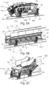
- Figures 5A to 5C several longitudinal section modules 11 of a modularly constructed and modularly assembled guideway device 10, namely Figure 5C a longitudinal section module 11b designed as a lower head module, Figure 5B a longitudinal section module 11c designed as an intermediate module, and Figure 5A a longitudinal section module 11a designed as an upper head module.
- the longitudinal section modules 11 each have a support structure 15 with two side wall units 17 and cross members 16.1.
- a respective side wall unit 17 has at least one side wall 17a, 17b, an upper flange 17.7 and a lower flange 17.9.
- the structure of the supporting structure 15 of the respective module consists of side walls or side wall units made largely of flat material.
- the side wall 17a, 17b is at least in an external plane and/or at least over a middle height section 15.1 in the Essentially made of flat material (the middle height section can certainly make up at least 75% or even at least 85% of the total height of the corresponding side wall/unit), with structural sections designed as structural posts and/or structural sections designed as simple diagonal or cross-shaped cross braces in the flat material being formed in the corresponding side wall plane or slightly offset therefrom through recesses made in the flat material.
- the offset arrangement in several planes can be realized, for example, by bending the flat material in one piece, at a single angle or at multiple angles.
- the structural sections designed as structural posts divide the side wall 17a, 17b or the corresponding side wall unit 17 into fields. Furthermore, support elements and cross braces 16.1 are arranged or fastened to the structural sections provided by the flat material, in particular welded or otherwise connected, for example by means of a material bond.
- the respective side wall 17a, 17b is further preferably formed integrally in one piece with the corresponding upper flange 17.7 and the lower flange 17.9, at least in sections; in particular, the flat material forming the respective side wall 17a, 17b forms a first wall (or a corresponding flat material section) and a second wall of the upper flange 17.7 bent in an L-shape from the first wall; a third wall and a fourth wall of the upper flange 17.7 are formed by a further structural element or section formed from an L-shaped bent flat material and welded to the flat material forming the corresponding side wall 17a, 17b.
- a first wall is formed on the lower flange 17.9 by the flat material forming the side wall bent in an L-shape from the side wall and a second wall is formed in an L-shape from the first wall; a third wall and a fourth wall of the lower chord 17.9 are formed by a base unit 14 which is bent into an L-shape at least in sections.
- the structural design of the upper and lower chords can be based on the same design principle, but differ in details such as the cross-sectional geometry and/or area, in particular because the lower chord is primarily subjected to tensile stress and the upper chord is primarily or at least largely subjected to compressive forces.
- This structural design in particular the use of flat material bent into an L-shape at least in individual sections, which is installed to form further profiles, also enables a good compromise between material use, strength, variability and precision. It has been shown that a particularly advantageous arrangement can be provided if several (preferably only two) flat material sections bent into an L-shape in the end area are welded together to form a closed (square) profile.
- the supporting structures of the longitudinal section modules 11 are in the Figures 5A to 5C in combination with other (built-in) components of the guideway device.
- the lower head module 11b has a comb plate, a base section and several guides for chain rollers, step/pallet rollers and/or handrails. Corresponding guide rails are also arranged on the intermediate module. The guide rails rest on structural sections (in particular made of flat material) of the support structure.
- the upper head module has (in particular in addition to the components already present in the lower head module and/or intermediate module) a drive for driving a chain and optionally also a handrail circuit.
- the upper head module 11a has a balustrade 12 with a handrail 13 arranged on it; the balustrade is connected to the support structure, as can be seen in particular from Fig. 5B visible.
- the longitudinal section modules 11 each have reference points 17.1 or corresponding geometrically predefined (in particular circular) reference recesses 17.3 introduced into the flat material on the supporting structures 15 or side wall units 17 or side walls 17a, 17b ( Fig. 5B ).
- the reference points 17.1 are partially covered by side support units 44 which are predefined positioned/positionable on support and movement devices 40a, 40b and which are connected by means of coupling units 46 ( Fig. 5C ) can be coupled to the reference points 17.1 (e.g. by means of plug-in coupling bolts which couple to the corresponding coupling points 45 of the support and movement devices 40a, 40b without tolerances).
- the reference points 17.1 are preferably formed as part of the manufacturing process of the side walls 17a, 17b on the corresponding structural section, in particular in the at least single-layer flat material, preferably by laser cutting, whereby thanks to a comparatively high level of accuracy (in particular in the case of a material processing process that is carried out partially or fully automated in the plane, e.g.
- tiltable storage or suspension/mounting of the longitudinal section modules 11 also ensures a comparatively exact alignment of the longitudinal section modules 11 relative to one another, in particular in connection with the pairwise connection/marriage of the modules to one another (if their abutment planes are aligned parallel to one another, in particular in each case in a connection plane predefined by a longitudinal section module connection arrangement with at least approximately vertical alignment), which also noticeably facilitates the use of the sheet metal connections described here in combination with, for example, essentially manually introduced force-locking/positive-locking connecting means 37 (in particular locking ring bolts) and the feasibility of the modular concept described here can be further improved.
- the present invention also makes it possible, in particular, to overcome disadvantages and handling difficulties associated with escalators 3 ( Fig.1 ) with standard construction, which require an inclined arrangement/alignment of all longitudinal sections or of the supporting structure already constructed over the entire longitudinal extent during a comparatively long phase of the manufacturing process.
- the respective module can be supported against the ground at support points 11.11 provided/provided for the module on the supporting structure.
- the support points 11.11 can be provided, for example, on the underside of the respective supporting structure and enable the respective longitudinal section module to be laid down/supported independently of support at the reference points, thus making handling even easier.
- the support points can also be used to temporarily store or transport the entire supporting structure after completion.
- the support structure 15 or the corresponding side wall can be provided with a tolerance-minimized (middle, at least approximately centrally arranged between the upper and lower flange) height section 15.1, in which a comparatively high position accuracy or a comparatively small tolerance can be ensured, in particular when the
- the corresponding support structure section is preferably formed in one piece from flat material.
- a comparatively large tolerance can also be uncritical. This also applies to a lower height section 15b of the support structure, in particular in the area of a/the floor unit.
- the present invention is also based on the concept of enabling referencing to this middle height section 15.1 during relative and/or absolute positioning by providing at least one, preferably at least two structurally loadable reference recesses in this middle height section, e.g. set up for support on side support units.
- the support structure 15 has, for example, several structural sections 15.3 (in particular flat material sections) and several support structure units 16, each with several profiles 16.1 or profile sections 16.1a with a hollow cross-section (in particular sheet metal profiles or flat material profiles), e.g. square profile sections, L-profile sections and/or U-profile sections. Individual surface sections or struts of the support structure units 16 can also be provided for connecting opposite side wall units.
- several support structure units 16 together form a longitudinal section module, e.g. if the intermediate module is to be composed of several similarly constructed support structure units 16 or is to be designed to be scalable and extendable.
- recesses 16.2 can be structurally planned in the area of a connection interface/plane.
- Adjacent side wall sections can preferably be connected to one another in a flat connection interface 18 by coupling corresponding form-fitting contours to one another, in particular for the purpose of subsequent material-locking connection at the connection interface.
- a form-fitting coupling is provided in particular for defining a relative position for subsequent welding of adjacent longitudinal sections, in each case by means of a first form-fitting contour on a first longitudinal section and a corresponding second form-fitting contour (in particular negative form) on a second longitudinal section, wherein several individual flange plate couplings (flat, acting two-dimensionally) can also be provided for each connection interface, in particular at height positions that are as far apart as possible. This promotes a high level of positional accuracy and reduces the risk of tilting/tensioning.
- the form-fitting contours described here also facilitate the arrangement of the corresponding material sections on a work table unit for the production of the side walls or the side wall units or the supporting structure of individual longitudinal sections or modules.
- a (load-)bearing module connection 30 is preferably provided, each comprising a plurality of sheet metal connections 31 with sheet metal angle units or plate units.
- the respective sheet metal connections 31 are preferably based on purely force-locking/positive locking connection technology, wherein the holding force produced is preferably a frictional force, i.e. can be ensured without a positive locking.
- the respective sheet metal connection 31 can comprise individual ones of the following connection components depending on the connection position: butt plate, inner angle or plate (in particular curved angle piece), angle/angle piece (in particular in a curved design), counter plate.
- connection components are connected to one another in a form-locking/positive locking manner by means of connecting means 37 (in particular screw connection or rivet connection), in particular such that the supporting structures of the adjacent longitudinal section modules are held together in a frictional manner.
- connecting means 37 in particular screw connection or rivet connection
- fastening axes are provided which are defined by the sheet metal connection and the supporting structure, in particular by several (through) holes or optionally fastening holes 35 which are at least partially designed as elongated holes (in particular oversized in the axial longitudinal direction for the purpose of position adjustment).
- Screws and/or rivets are suitable as connecting means 37, whereby a lock nut or a similarly acting counterpart (e.g. a locking ring bolt connection) is also preferably provided.
- a longitudinal section module connection arrangement 40 (or module connection process arrangement) enables the individual longitudinal section modules to be connected/married, wherein the handling and relative positioning can be carried out in an advantageous manner.
- the respective longitudinal section module can be supported against the ground by means of support and movement devices 40a, 40b or correspondingly acting supports (assembly aids) (in particular first and second support and movement devices 40a, 40b for each longitudinal section module), wherein a lifting or tilting kinematics 41 can also be integrated into the individual support and movement devices;
- a tilting device 42 enables a movement in the form of tilting about a transverse axis for positioning a/the desired longitudinal section, for example for aligning a respective platform section in an inclined position in order to be able to position the corresponding inclined section in a horizontal alignment on the adjacent intermediate module.
- the support and movement devices 40a, 40b can be mounted on wheels or Rollers 43 can be mounted.
- the support and movement devices 40a, 40b can preferably also each comprise side support units 44, by means of which the respective module can be supported via reference recesses made in the side wall units and positioned with minimal tolerances.
- coupling points 45 arranged in a predefined manner with high precision can be provided on the side support unit 44, to which coupling units 46 (e.g. plug-in coupling bolts) can be coupled.
- the longitudinal section module connection arrangement 40 or a corresponding section of a/the assembly line 100 can, depending on the preferred design of the assembly method, comprise further positioning units 50 (in particular equipped with guides or plug connections 53 on alignment plates 51), wherein the respective side support unit 44 preferably couples in a standardized manner to a/the correspondingly provided positioning unit 50.
- the side support units 44 can optionally be designed as comparatively slim side arm levers (eg also individually for each type of travel device), and the positioning units 50 can eg be provided as largely standardized assembly aids by means of which the support on the ground is carried out. This further reduces the effort for any desired type-specific adaptation of assembly aids.
- the longitudinal section module connection arrangement 40 is preferably provided as a component of an assembly line 100 for assembling support structures of modularly constructed guideway devices (in particular process/production lines), namely in the end region of this assembly line 100, on which the individual longitudinal section modules are preferably already arranged and supported in a phase of module-specific assembly in the intended order and optionally also in an alignment coordinated for the connection.
- the assembly line 100 can also comprise one or more alignment devices 101 (e.g.
- a clamp (clamp connection) enables individual assembly aids to be held/fixed temporarily.
- the assembly line 100 also includes a spatially planned cavity or assembly space 110 below the alignment/support plane of the respective intermediate module, in particular a space below the floor level, so that the intermediate modules can also be advantageously arranged flat above the floor when aligned horizontally (both for the module-specific assembly as well as for completing the entire supporting structure by connecting/marrying the individual modules).
- connection plane is to be understood as an end side defined at least by the ends of the supporting structure of the respective module, on/in which a connection is provided in an abutting arrangement with the adjacent module, and the "connection plane” is to be understood in a narrower sense, also in a mathematical/geometric sense, as a plane in which the respective applied connecting means should be arranged or at least act.
- several connecting means can be provided which are arranged axially overlapping the joint plane(s) in several connecting planes, e.g. parallel and/or orthogonal to one another, or which act in each case there.
- step S1 The material intended for the creation of the support structure, in particular in the form of a flat material, is subjected to material processing (step S1 ) comprising a material recess, in particular by laser cutting; this processing step is preferably carried out when the flat material is arranged on a work table. In this way, in particular the essential sections of the respective side wall (unit) can also be created.
- step S2 a material-locking connection, in particular welding with a comparable arrangement of the flat material (on a/the same) work table.
- butt welding can also be carried out in the area of the bend, in particular after the corresponding adjoining longitudinal sections of the head module in question have been positioned in a form-fitting manner relative to one another on correspondingly introduced form-fitting contours.
- a module-specific assembly (step S3) of at least the most important support structure components can then take place (side wall units or at least side walls and crossbars), optionally in the same plane or on that work table (or in its extension), which was used for steps S1 and/or S2.
- step S4 arranging and aligning (or relative positioning) of several modules (step S4) in such a way that the modules can remain in the selected relative arrangement to one another in the further course of the production process, i.e.
- module-specific handling and module-specific assembly (step S5) of, for example, built-in components can be provided, with the respective module being advantageously aligned, in particular in a horizontal plane (head modules with their platform section in horizontal alignment).
- a preferably form-fitting/non-positive connection of several modules can then be carried out to form the supporting structure of the entire guideway device, whereby the head modules are preferably only tilted about a reference axis to align the inclined section of the respective head module in a/the horizontal plane in which the intermediate module is/remains preferably arranged.
- the guideway device can then be completed (step S7), e.g. by further assembly measures, for example relating to the balustrade or completing the peripheral drive or handrail components or installing the steps (the latter can optionally also be carried out on a module-specific basis).
- Steps S4 to S6 and optionally also S7 are preferably carried out in the same assembly line, i.e. with the order of the individual modules unchanged and with aligned alignment in the longitudinal direction of the assembly line.
- steps S4 to S6 reference is preferably made to reference recesses provided integrally in the respective module-specific support structure, with these reference recesses preferably being introduced in step S1 in a module-specific manner.
- the reference recesses described here can also be used for the arrangement of adapter plates, in particular in a preparatory phase when positioning two modules face to face, before the modules are connected/married in a form-fitting/non-positive manner.
- the adapter plates can be mounted on the reference recesses of a first module and facilitate the aligned docking of the adjacent (second) module, in particular by providing corresponding tapered guides (at least one) on the respective adapter plate; the adapter plates are advantageously mounted on the outside of the respective side wall, in particular at least approximately centrally with respect to the total height of the cross-section of the support structure.
- a corresponding guide bolt can be mounted on the adjacent (second) module, in particular also on at least one reference recess, in particular also in the relative position described here relative to the support structure.
- Such adapter plates can be provided in a simple and cost-effective manner, in particular from sheet metal.
- Fig.1 A conventional orientation of an escalator 3 in the manner of a lying Z-letter is illustrated. In this orientation, however, many assembly and handling processes are disadvantageously complicated.
- the two head modules 11a, 11b of a modularly available guideway device are shown in an arrangement resting on support and movement devices 40a, 40b and with the respective platform section 11.1 in at least approximately, preferably exactly horizontal alignment (horizontal plane Exy).
- horizontal plane Exy horizontal alignment
- the installation of drive components or other installation components is also considerably easier.
- Fig.3 illustrates, among other things, the process-related advantage associated with the present invention of an advantageous arrangement/alignment of the individual modules on the one hand in a phase of module-specific assembly/mounting, on the other hand also in/for an assembly line 100 for the assembly of the entire support structure or the complete guideway device.
- the individual modules are still accessible from the front and advantageously aligned (in particular exactly horizontally), nevertheless the modules can be brought into a final relative position by a comparatively slim process by a comparatively short/small translation movement (x) and by tilting (head modules), in particular about the reference axes (y) provided integrally by the side wall units described here, and can be positioned/held there comparatively exactly (as e.g. in the Fig.6 shown relative position).
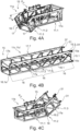
- Fig. 4A, 4B, 4C further details of the supporting structure 15 of the respective module 11a, 11b, 11c are shown.
- the structural features are already described in detail elsewhere; in this respect, no further details can be given with regard to the Figures 4
- the respective module 11a, 11b, 11c is advantageous for all module-specific steps and measures, e.g. a module-specific installation of drive components, especially on the head module 11a. can be arranged and aligned, in particular until a module-specific configuration is created as described in the Figures 5 shown.
- the modules 11a, 11b, 11c can be arranged in the intended order and also in the corresponding plane already in the phase of module-specific measures (in particular step S5), in particular by means of the support and movement devices 40a, 40b shown here, which are guided on rails 101, for example.
- the head module is arranged in the assembly direction (or in the longitudinal direction X100) in front of the at least one intermediate module.
- the Fig. 5C The reference symbol (30) shown in brackets is intended to illustrate that the sheet metal connections 31 shown, when assembled, together form a load-bearing module connection 30 between two supporting structures married to one another.
- the respective side wall is optionally designed as a flat material section with recesses made in it (e.g. laser-cut recesses that result in an X-arrangement of diagonal strut sections, e.g. laser-cut X-contour), or has diagonal struts designed as welded profiles (in particular folded U-profiles), which interact with the flat material or are integrated into the structure via flat material sections.
- recesses e.g. laser-cut recesses that result in an X-arrangement of diagonal strut sections, e.g. laser-cut X-contour
- diagonal struts designed as welded profiles in particular folded U-profiles
- Fig.6 individual modules 11a, 11b, 11c, 11c' of a guideway device 10 are shown in a phase of the assembly process in which the adjacent and to be connected joint planes are already aligned parallel to each other, in particular in that the head modules 11a, 11b are/were tilted about the reference axes provided integrally by the side wall units of the respective module and supported on the support and movement devices 40a, 40b, optionally using a lifting/tilting kinematics 41, which can be activated or operated, for example, by means of a tilting device 42 provided on the respective support and movement device.
- a hoist can also be used be provided, depending on the equipment of a machine hall.
- the tipping device(s) 42 indicated here can advantageously be used to ensure handling without a crane or load transfer devices arranged above the modules; this also increases variability/flexibility and also occupational safety, thus also reducing the safety requirements placed on the process.
- step S1 material processing
- step S2 material-locking connection
- step S3 module-specific assembly of at least the most important support structure components (side wall units or at least side walls and cross bars).
- step S4 This is then preferably followed by arranging and aligning (or relatively positioning) several modules (step S4 ) in such a way that the modules can remain in the selected relative arrangement to one another during the further course of the creation process, in particular with the intermediate module and the respective platform section 11.1 of the head modules in a precisely horizontal alignment (working plane Exy).
- module-specific handling and module-specific assembly of, for example, built-in components can be provided (step S5 ); in particular, drive components and guide rails provided for step rollers, for example, are mounted.
- a preferably positive/non-positive connection of several modules can then take place to form the supporting structure of the entire guideway device, wherein the head modules are preferably only tilted about a/the corresponding reference axis for this purpose, in order to align the joint plane of the respective module, in particular in an at least approximately vertical connection plane.
- the positive/non-positive connection can be carried out by means of optionally pre-assembled sheet metal connections, in particular in the area of the respective upper/lower chord.
- the guideway device can then be completed (step S7 ), e.g. by further assembly measures, for example relating to the balustrade or completing all-round drive or handrail components or installing the steps.
- Steps S4 to S6 are preferably carried out in the same assembly line, with the order of the individual modules unchanged and with aligned alignment in the longitudinal direction of the assembly line, whereby during alignment, support and positioning, the integrally formed in the respective Reference is made to the reference recesses provided in the module-specific supporting structure.
Landscapes
- Escalators And Moving Walkways (AREA)
- Automatic Assembly (AREA)
Priority Applications (6)
| Application Number | Priority Date | Filing Date | Title |
|---|---|---|---|
| EP22200508.4A EP4353652A1 (fr) | 2022-10-10 | 2022-10-10 | Procédé d'assemblage modulaire d'au moins un module de section longitudinale d'un dispositif de voie de circulation à assemblage modulaire, dispositif de voie de circulation |
| EP22202864.9A EP4353664A1 (fr) | 2022-10-10 | 2022-10-20 | Dispositif de voie de circulation comportant au moins trois sections longitudinales, procédé et utilisation |
| CN202380071843.8A CN120019019A (zh) | 2022-10-10 | 2023-09-22 | 用于对可模块式组装的行进装置的至少一个纵向区段模块进行模块方式组装的方法、以及行进装置 |
| PCT/EP2023/076212 WO2024078838A1 (fr) | 2022-10-10 | 2023-09-22 | Procédé d'assemblage modulaire d'au moins un module de section longitudinale d'un système de guidage pouvant être assemblé d'une manière modulaire, et système de guidage |
| CN202380071954.9A CN120035560A (zh) | 2022-10-10 | 2023-09-27 | 具有至少三个纵向区段的行进装置、以及方法和应用 |
| PCT/EP2023/076727 WO2024078878A1 (fr) | 2022-10-10 | 2023-09-27 | Système de guidage comprenant au moins trois sections longitudinales, procédé et utilisation |
Applications Claiming Priority (1)
| Application Number | Priority Date | Filing Date | Title |
|---|---|---|---|
| EP22200508.4A EP4353652A1 (fr) | 2022-10-10 | 2022-10-10 | Procédé d'assemblage modulaire d'au moins un module de section longitudinale d'un dispositif de voie de circulation à assemblage modulaire, dispositif de voie de circulation |
Publications (1)
| Publication Number | Publication Date |
|---|---|
| EP4353652A1 true EP4353652A1 (fr) | 2024-04-17 |
Family
ID=83689634
Family Applications (1)
| Application Number | Title | Priority Date | Filing Date |
|---|---|---|---|
| EP22200508.4A Pending EP4353652A1 (fr) | 2022-10-10 | 2022-10-10 | Procédé d'assemblage modulaire d'au moins un module de section longitudinale d'un dispositif de voie de circulation à assemblage modulaire, dispositif de voie de circulation |
Country Status (3)
| Country | Link |
|---|---|
| EP (1) | EP4353652A1 (fr) |
| CN (1) | CN120019019A (fr) |
| WO (1) | WO2024078838A1 (fr) |
Citations (6)
| Publication number | Priority date | Publication date | Assignee | Title |
|---|---|---|---|---|
| JP2006213470A (ja) * | 2005-02-03 | 2006-08-17 | Toshiba Elevator Co Ltd | 乗客コンベアの搬送方法および乗客コンベアの搬送装置 |
| JP2006232489A (ja) * | 2005-02-25 | 2006-09-07 | Hitachi Ltd | 傾斜型乗客コンベア設備及びその設置方法並びにその搬出方法 |
| EP3426589A1 (fr) | 2016-03-10 | 2019-01-16 | Inventio AG | Procédé de réalisation à assistance robotique d'une ossature d'une installation de transport de personnes |
| EP3426588A1 (fr) | 2016-03-10 | 2019-01-16 | Inventio AG | Dispositif de réalisation à assistance robotique d'une ossature d'une installation de transport de personnes |
| EP3724118A1 (fr) | 2017-12-14 | 2020-10-21 | Inventio AG | Procédé et dispositif de mise en service d'un système de transport de personnes à fabriquer, au moyen de la création d'un double numérique |
| CN110449785B (zh) * | 2019-08-13 | 2021-05-25 | 上海三菱电梯有限公司 | 自动扶梯或自动人行道的桁架的制造系统及制造工艺 |
Family Cites Families (1)
| Publication number | Priority date | Publication date | Assignee | Title |
|---|---|---|---|---|
| DE202004004178U1 (de) * | 2004-03-17 | 2004-09-23 | Thyssenkrupp Fahrtreppen Gmbh | Fahrtreppe oder Fahrsteig |
-
2022
- 2022-10-10 EP EP22200508.4A patent/EP4353652A1/fr active Pending
-
2023
- 2023-09-22 WO PCT/EP2023/076212 patent/WO2024078838A1/fr not_active Ceased
- 2023-09-22 CN CN202380071843.8A patent/CN120019019A/zh active Pending
Patent Citations (6)
| Publication number | Priority date | Publication date | Assignee | Title |
|---|---|---|---|---|
| JP2006213470A (ja) * | 2005-02-03 | 2006-08-17 | Toshiba Elevator Co Ltd | 乗客コンベアの搬送方法および乗客コンベアの搬送装置 |
| JP2006232489A (ja) * | 2005-02-25 | 2006-09-07 | Hitachi Ltd | 傾斜型乗客コンベア設備及びその設置方法並びにその搬出方法 |
| EP3426589A1 (fr) | 2016-03-10 | 2019-01-16 | Inventio AG | Procédé de réalisation à assistance robotique d'une ossature d'une installation de transport de personnes |
| EP3426588A1 (fr) | 2016-03-10 | 2019-01-16 | Inventio AG | Dispositif de réalisation à assistance robotique d'une ossature d'une installation de transport de personnes |
| EP3724118A1 (fr) | 2017-12-14 | 2020-10-21 | Inventio AG | Procédé et dispositif de mise en service d'un système de transport de personnes à fabriquer, au moyen de la création d'un double numérique |
| CN110449785B (zh) * | 2019-08-13 | 2021-05-25 | 上海三菱电梯有限公司 | 自动扶梯或自动人行道的桁架的制造系统及制造工艺 |
Also Published As
| Publication number | Publication date |
|---|---|
| CN120019019A (zh) | 2025-05-16 |
| WO2024078838A1 (fr) | 2024-04-18 |
Similar Documents
| Publication | Publication Date | Title |
|---|---|---|
| EP4313836B1 (fr) | Structure porteuse d'un escalier roulant ou d'un tapis roulant | |
| EP3356277B1 (fr) | Procédé de montage d'une ossature porteuse pour une installation de transport de personnes dans un bâtiment | |
| EP2150373B1 (fr) | Poste d'usinage, en particulier de soudage géométrique présentant des armatures de serrage mobiles dotées d'entretoises respectives | |
| WO2017153314A1 (fr) | Dispositif de réalisation à assistance robotique d'une ossature d'une installation de transport de personnes | |
| WO2017153324A1 (fr) | Procédé de réalisation à assistance robotique d'une ossature d'une installation de transport de personnes | |
| EP2161237A2 (fr) | Transstockeur doté d'un mât | |
| EP2882634B1 (fr) | Structure de convoyeur aerien au-dessus d'un portique | |
| EP3016843B1 (fr) | Convoyeur aérien équipé de modules de châssis porteur | |
| WO2024078841A1 (fr) | Ensemble raccordement de module de section longitudinale et procédé d'assemblage d'appareil à chenille | |
| EP4353658B1 (fr) | Procédé d'assemblage d'un dispositif de voie modulaire et dispositif et utilisation | |
| EP4353652A1 (fr) | Procédé d'assemblage modulaire d'au moins un module de section longitudinale d'un dispositif de voie de circulation à assemblage modulaire, dispositif de voie de circulation | |
| EP3150540A1 (fr) | Procede de fabrication d'une ossature porteuse pour une installation de transport de personnes | |
| EP3049316B1 (fr) | Système de convoyeur aérien à monter au plafond d'une ligne de montage | |
| EP4353660A1 (fr) | Dispositif de voie de circulation comprenant au moins trois modules de section longitudinale avec des sections longitudinales pouvant être accouplées par complémentarité de forme ainsi que procédé d'assemblage et utilisation | |
| EP4353655A1 (fr) | Dispositif de voie modulaire a liaison modulaire moule/force, et procédé et utilisation | |
| EP4353654A1 (fr) | Dispositif de voie de circulation comportant au moins trois sections longitudinales, procédé et utilisation | |
| EP4353664A1 (fr) | Dispositif de voie de circulation comportant au moins trois sections longitudinales, procédé et utilisation | |
| WO2024078878A1 (fr) | Système de guidage comprenant au moins trois sections longitudinales, procédé et utilisation | |
| EP4353650B1 (fr) | Structure de support pour un dispositif de voie de circulation | |
| DE29720801U1 (de) | Aufbauplattform für Elemente einer Fertigungsstraße | |
| EP4353656A1 (fr) | Structure de support pour un dispositif de voie de circulation | |
| EP4353651A1 (fr) | Structure de support pour un dispositif de voie de circulation | |
| EP4353661A1 (fr) | Socle pour dispositif de voie modulaire | |
| EP4551492B1 (fr) | Dispositif d'alignement pour zones d'assemblage des sections d'ossature porteuse | |
| EP3150539A1 (fr) | Ossature porteuse pour une installation de transport de personnes |
Legal Events
| Date | Code | Title | Description |
|---|---|---|---|
| PUAI | Public reference made under article 153(3) epc to a published international application that has entered the european phase |
Free format text: ORIGINAL CODE: 0009012 |
|
| STAA | Information on the status of an ep patent application or granted ep patent |
Free format text: STATUS: THE APPLICATION HAS BEEN PUBLISHED |
|
| AK | Designated contracting states |
Kind code of ref document: A1 Designated state(s): AL AT BE BG CH CY CZ DE DK EE ES FI FR GB GR HR HU IE IS IT LI LT LU LV MC ME MK MT NL NO PL PT RO RS SE SI SK SM TR |
|
| STAA | Information on the status of an ep patent application or granted ep patent |
Free format text: STATUS: REQUEST FOR EXAMINATION WAS MADE |
|
| 17P | Request for examination filed |
Effective date: 20240507 |
|
| RBV | Designated contracting states (corrected) |
Designated state(s): AL AT BE BG CH CY CZ DE DK EE ES FI FR GB GR HR HU IE IS IT LI LT LU LV MC ME MK MT NL NO PL PT RO RS SE SI SK SM TR |
|
| STAA | Information on the status of an ep patent application or granted ep patent |
Free format text: STATUS: EXAMINATION IS IN PROGRESS |