EP4353651A1 - Structure de support pour un dispositif de voie de circulation - Google Patents
Structure de support pour un dispositif de voie de circulation Download PDFInfo
- Publication number
- EP4353651A1 EP4353651A1 EP22200507.6A EP22200507A EP4353651A1 EP 4353651 A1 EP4353651 A1 EP 4353651A1 EP 22200507 A EP22200507 A EP 22200507A EP 4353651 A1 EP4353651 A1 EP 4353651A1
- Authority
- EP
- European Patent Office
- Prior art keywords
- support structure
- side wall
- profile
- designed
- structural
- Prior art date
- Legal status (The legal status is an assumption and is not a legal conclusion. Google has not performed a legal analysis and makes no representation as to the accuracy of the status listed.)
- Pending
Links
- 238000003698 laser cutting Methods 0.000 claims abstract description 27
- 239000000463 material Substances 0.000 claims description 36
- 238000005253 cladding Methods 0.000 claims description 8
- 239000002184 metal Substances 0.000 claims description 4
- 229910000831 Steel Inorganic materials 0.000 claims description 2
- 239000007769 metal material Substances 0.000 claims description 2
- 239000010959 steel Substances 0.000 claims description 2
- 230000008901 benefit Effects 0.000 description 8
- 238000004519 manufacturing process Methods 0.000 description 7
- 238000005452 bending Methods 0.000 description 5
- 238000000034 method Methods 0.000 description 4
- 238000003672 processing method Methods 0.000 description 3
- 239000011265 semifinished product Substances 0.000 description 3
- 238000010276 construction Methods 0.000 description 2
- 238000003466 welding Methods 0.000 description 2
- 230000008859 change Effects 0.000 description 1
- 230000006835 compression Effects 0.000 description 1
- 238000007906 compression Methods 0.000 description 1
- 230000001627 detrimental effect Effects 0.000 description 1
- 230000004069 differentiation Effects 0.000 description 1
- 238000005516 engineering process Methods 0.000 description 1
- 230000002349 favourable effect Effects 0.000 description 1
- 230000008569 process Effects 0.000 description 1
- 239000000725 suspension Substances 0.000 description 1
- 230000007704 transition Effects 0.000 description 1
Images
Classifications
-
- B—PERFORMING OPERATIONS; TRANSPORTING
- B66—HOISTING; LIFTING; HAULING
- B66B—ELEVATORS; ESCALATORS OR MOVING WALKWAYS
- B66B23/00—Component parts of escalators or moving walkways
Definitions
- the present invention relates to a support structure for a guideway device, in particular an escalator device, having at least one side wall unit with an upper chord, a lower chord and a side wall extending between the upper chord and the lower chord. Furthermore, the present invention relates to a longitudinal section module of a guideway device that can be assembled in modules, in particular an escalator device, with such a support structure and a corresponding guideway device.
- Support structures for guideway devices or guideway devices themselves are basically known from the state of the art.
- Support structures form the external supporting structure for components of the guideway device, such as guides with steps/pallets embedded therein, drives and electrical systems as well as for attachment and cladding elements and are usually made up of two side wall units that are opposite one another and connected via cross beams.
- the side wall units usually have profiles welded together as structural elements, from which lattice-like side walls and an upper and lower chord are formed.
- appropriate fastening means are designed for variable positioning/alignment of the component relative to the supporting structure and/or must be laboriously created manually after positioning and/or alignment.
- EP 1 321 424 B1 A supporting structure for an escalator or moving walkway is known, which has a lattice element that is designed as a single piece and as a flat, unprofiled, cut plate. The welding work required to build the supporting structure is thus reduced.
- a support structure for a guideway device in particular an escalator device, comprising at least one side wall unit with an upper chord, a lower chord and a side wall extending between the upper chord and the lower chord, wherein at least one of the upper chord and/or lower chord is designed as a profile separate from the side wall and forms a connection with the side wall, wherein the at least one profile has at least one first recess for connecting, receiving and/or interacting the profile with a further component of the guideway device and wherein the at least one first recess is formed by means of laser cutting and is positioned in a defined manner relative to a reference point of the support structure.
- first element For example "first element”, “second element” and “third element”, this numbering is intended purely for differentiation in the designation and does not represent a dependency of the elements on one another or a mandatory order of the elements.
- the device or method can also have a "first element” and a “third element” without necessarily having a "second element”.
- Several units of an element of a single numbering can also be provided, for example several "first elements”.
- guideway device refers primarily to escalator devices and moving walkway devices (the latter in particular in a stepless design in an at least approximately flat alignment or with a negligible gradient) as well as related passenger transport devices with a continuously rotating transport device.
- a guideway device comprises, for example, segments or units forming the transport device, in particular steps or pallets, which are connected to driven chains or comparable drive means and guided in guides.
- the guides as well as a/the chain (or a comparable traction device) and other components of the guideway device are held, for example, within support structures extending longitudinally essentially laterally therefrom, which are usually formed from two side wall units lying opposite one another and connected to one another via crossbeams and optionally also a floor unit.
- guideway device also refers in particular to modularly constructed guideway devices which are modularly constructed from several longitudinal sections or longitudinal section modules, each with an individual or individually created support structure, and which can be assembled/mounted in modules.
- the support structure of the guideway device or the respective module is preferably formed essentially by opposing side wall units and cross members (also referred to as crossbars) connecting them, with each side wall unit being formed by at least one side wall and in particular by an upper flange and/or a lower flange.
- the modular manufacturing process described here can also include the connection of a floor unit to the side wall units, but it has been shown that such a floor unit does not necessarily have to fulfill a support function, but is designed, for example, with regard to the function of collecting oil from a drive and, if necessary, draining it away, or is designed to be optimized with regard to a cover and/or accessibility from below to the support structure or the guideway device; in this respect, the floor unit is to be understood as an optional structural unit which can also be functionally provided separately from the support structure, but which can optionally also take on an additional supporting load-bearing function if desired in individual cases.
- side wall refers to a side structure that, for example, runs flat in only one side plane at least in sections, but is alternatively or additionally formed and/or reinforced at least in sections by profiles, struts or supports that extend beyond one/the side plane.
- the side wall is made up of structural elements or structural sections that, as flat structural sections, absorb forces in several directions and/or, as rod-shaped or strut-like structural elements/sections, absorb the respective forces only along the longitudinal extension specified by the orientation (tension or compression).
- the side wall is therefore designed, for example, as a closed surface, as a pure framework or as a structure with parts of closed surfaces and parts with a framework structure.
- the structural elements/sections of the side wall are made of flat material, in particular sheet metal, e.g. structurally flat sections or stiffening (in particular) curved L- or U-profile sections in the area of welded connections to other structural elements/sections.
- a “side wall unit” as understood in the present disclosure comprises the side wall described above as well as further structural elements/sections of this Belts associated with the side wall, in particular an upper belt and a lower belt. These belts are alternatively also referred to as bands.
- the respective side wall/unit can also be understood as a side wall/unit provided in modules, depending on the reference to a/the respective phase of the manufacturing process of the individual modules or of the entire guideway device.
- the term side wall unit can refer to the entire side structure comprising the upper and lower belts, and the term side wall can refer to the side structure arranged between the upper and lower belts.
- upper chord and lower chord which are also referred to together as belts, refer to structural elements extending longitudinally in the area of an upper edge or a lower edge of the side wall for absorbing loads in the longitudinal direction of the guideway device, in particular bending loads, which primarily lead to tensile stresses in the lower chord and to compressive stresses in the upper chord.
- the belts are preferably designed as profiles or profile sections, in particular as L-profiles, U-profiles or preferably rectangular hollow profiles and thus have a favorable area moment of inertia for absorbing the bending loads.
- the belts therefore stiffen the support structure and form outer corner points, with the belts and/or the side walls optionally serving to attach further components of the guideway device.
- the belts are designed as components separate from the side wall and are connected to the side wall, for example by means of welded connections, screw connections, rivet connections or the like.
- the connection between the belts and the side wall is particularly preferably designed in such a way that the belts and the side wall are positioned in a defined manner relative to one another.
- corresponding stops or similar shapes are provided on the belts and/or the side wall in order to position them in relation to one another before or during connection.
- such shapes are formed on the belts and/or the side walls by means of laser cutting, for example as mutually corresponding recesses or recesses on the one hand and projections provided for engagement in the recesses on the other.
- Such recesses formed by means of laser cutting are then preferably positioned in a defined manner relative to the reference point, so that the profile of the side wall forms a defined positioned connection.
- at least one recess positioned in a defined manner relative to the reference point is arranged on the side wall, wherein at least one recess formed by means of laser cutting is arranged on the profile, wherein the recesses form the connection with one another and with corresponding connecting means.
- components refers to all parts of the respective guideway devices, in particular the supporting structure or parts thereof and elements to be mounted in the guideway device or the respective modules of the guideway device, e.g. relating to electrics, drive, guidance, attachment/cladding elements or the like.
- a (corresponding) laser cutting tool is designed in particular for processing from one direction, with a laser head aligned perpendicular to the workpiece and designed to be movable relative to the workpiece in a plane parallel to the workpiece.
- the laser head can also be aligned in a manner deviating from its vertical orientation.
- a laser cutting tool can also comprise a laser head that is spatially movable around a workpiece, in particular the profile, whereby recesses can be made on the profile from any spatial direction and independently of the geometry of the profile, which is particularly advantageous.
- Laser cutting is also referred to as tube laser cutting for profiles with opposing walls, in particular hollow profiles.
- a reference point is understood to be a material point of a component to which positioning in at least one spatial direction is possible with precise dimensions. This is, for example, an edge or corner of a component, a connecting means provided on the component and/or a recess or projection provided in the component.
- a round recess is provided as a reference point, which is defined as a reference point by its center and enables the engagement of an assembly aid such as a bracket or a gauge.
- the solution to the problem with the support structure described above now includes the teaching that a first recess for positioning components is formed on the profile forming the relevant belt by means of laser cutting and thus with the precision or the low tolerances typical for laser cutting.
- the first recess is positioned in a defined manner relative to the reference point so that the support structure as a whole forms a referencing system on which components can be positioned without further aids and with little effort.
- the reference point is also provided, for example, on the belt having the first recess.
- the reference point is preferably provided on the side wall, wherein the belt having the first recess and the side wall are positioned in a defined manner relative to one another so that the referencing accuracy extends through the entire side wall unit.
- the present disclosure is based in particular on the concept that at least a significant portion of the side wall defining the overall shape is made of flat material, in particular sheet metal, with at least one reference point being defined on the flat material.
- This precision is continued by defined positioning of the upper belt and/or lower belt relative to the side wall towards the belt, so that the first recess is also positioned in a defined manner relative to the at least one reference point.
- the invention particularly preferably includes the teaching of introducing further references, in particular corresponding recesses (in the sense of additional component-specific assembly reference points), into the flat material or the profile in addition to the at least one reference point arranged in particular in the corresponding side wall during the same processing method, on which further components can be arranged directly and thus in a defined position relative to the at least one (master) reference point with high accuracy.
- the references are also introduced in particular in areas of the flat material which can be subjected to further processing steps, in particular bending processes, following the aforementioned processing method, whereby the referencing concept described here can also be implemented for multi-dimensional positioning in space with respect to at least two or all three spatial directions.
- the described referencing system also has the advantage of creating a particularly light supporting structure compared to the usual truss construction.
- a belt by bending the flat material from the side wall or integrated with the side wall.
- the teaching of the disclosure of forming the belt in question as a profile provided separately from the side wall has the advantage that corresponding profiles are usually available as semi-finished products with significantly greater lengths than is usual for flat materials or are significantly have longer lengths that can be processed using laser cutting than flat materials.
- the side wall can then be formed in one piece over a longer length in the upper and/or lower chord, so that longitudinal connections that are necessary for flat materials and detrimental to dimensional accuracy can be dispensed with.
- the use of a profile for the chord(s) has the advantage that by selecting a sufficient wall thickness for the loads expected in a guideway device, the weight and material used in the support structure can be reduced without having to change the external dimensions of the profile.
- the support structure can therefore be designed for different guideway devices or for different loads without changing its essential geometry.
- when processing the profile using laser cutting for different wall thicknesses only the design or strength of the laser changes, but not the program for moving the laser head.
- the present teaching combines - generally speaking - the advantages of profiles and flat materials mentioned in the side wall unit.
- the disclosure further includes the teaching that the reference point is defined by, for example, a circular recess or by its center, to which further positioning devices (i.e. assembly aids such as lateral support units) can be clamped for positioning individual longitudinal sections or components.
- the respective component with the reference point or the entire module or even the entire guideway device is lifted at at least one reference point or supported around a reference axis formed by several reference points, e.g. also suspended from it or lifted or tilted around it.
- the profile is designed as a hollow profile.
- Hollow profiles preferably have particularly good area moments of inertia and are therefore particularly well suited to supporting loads on a belt of a supporting structure.
- Laser cutting is then preferably carried out as tube laser cutting.
- the profile is preferably designed as a rolled profile.
- Rolled profiles have large available semi-finished product lengths, which are essentially transport-related and not are limited in terms of production technology. For example, such semi-finished products are up to 12m long.
- rolled profiles have a comparatively good accuracy, i.e. a small deviation from their target shape, and are therefore particularly suitable for implementing a previously described referencing system on the supporting structure.
- the profile is also preferably made of a metal material, in particular a steel material, and can then be advantageously formed or formed with high accuracy and high load-bearing capacity.
- the side wall is made of a flat material, in particular of a metal sheet.
- the flat material is positioned in a defined manner relative to the profile, in particular by corresponding shapes/recesses on the flat material and/or the profile, which correspond to one another for positioning the profile on the flat material.
- the flat material preferably has the reference point as a recess formed by means of laser cutting. The reference point is then arranged on the flat material in an accessible manner during assembly of the guideway device.
- the reference point has a particularly high dimensional accuracy in relation to other references arranged on the flat material due to the one-piece nature of the flat material.
- the side wall preferably has several fields and between two fields a structural section designed as a structural post or a structural element designed as a structural post.
- a structural post is a structural element/section running along the side wall in a vertical direction, which is preferably formed at recurring intervals along the longitudinal extension of the side wall.
- the structural post is formed in one piece or integrated with a part of the side wall that essentially defines the side wall in terms of its overall shape, is arranged on such a part as a separate component or forms a structural element/section of the side wall.
- the structural post serves to stiffen the side wall or the supporting structure and/or to absorb loads on the side wall or the supporting structure.
- structural sections or structural elements are arranged in a cross shape in at least one field.
- the structural sections/structural elements are thus arranged in the manner of diagonal struts and form a stiffening structure in the side wall, which connects two structural posts to one another and is designed in particular to stiffen the belts that bear bending loads relative to one another.
- structural sections are formed on the flat material, these can be formed by recesses provided on the flat material. For example, free spaces of a lattice structure are recessed on the flat material, so that remaining structural sections are formed in the manner of struts of a lattice.
- These structural sections can also be supplemented or partially replaced by (attached) structural elements, in particular profiles, whereby the one-piece flat material preferably forms the essential basic structure of the side wall/unit and thus references arranged therein have a defined relationship to the reference point.
- the recesses are preferably formed by means of laser cutting. This is particularly advantageous if the flat material is already processed in a laser cutting tool to form the reference point and/or further references. A plurality of processing steps are then carried out together and with high precision or low tolerances and the number of separate processing steps is advantageously reduced.
- the at least one first recess is designed to connect, receive and/or interact with the profile with a structural element/structural section of the support structure - in particular a side wall and/or a structural post, a cladding element, an attachment/cladding element and/or a profile of another support structure.
- the straps are designed in particular to receive attachments, such as a balustrade or a cam plate, or of cladding elements of the guideway device.
- a first recess is preferably designed as a connecting means for connecting to a profile of another support structure.
- Such a connecting means is used in particular for connecting longitudinal section modules of a guideway device that can be assembled in modules, wherein preferably both longitudinal section modules can be referenced to the same reference point.
- longitudinal section module of a guideway device that can be assembled in modules, in particular an escalator device, having a support structure as described above.
- longitudinal section module is to be understood in the sense of the present disclosure generally as a longitudinal module of the guideway device, i.e. as a module that forms a longitudinal or length section of the guideway device (i.e. a component that is at least structurally complete in the corresponding length range). This term therefore includes the terms "head module” and "intermediate module".
- head module refers to a module arranged at one of the ends of the guideway device and refers optionally to both types of head modules (upper and lower head module, also referred to as upper part and lower part); in this respect, this term can equally refer to the module at the upper or lower end of the guideway device.
- Head modules usually extend over one/the angle of inclination of the guideway device, i.e. they span the bend or the transition from the inclined longitudinal section to the respective horizontal section.
- the term “platform section” refers to the section of the respective head module that is aligned at least approximately in a horizontal plane in the intended arrangement; in this respect, when describing the arrangement/alignment of the respective head module, reference is also made to the alignment of this platform section (or its main extension plane), in particular if the absolute length of the platform section is greater than the absolute length of the inclined section.
- the term “connecting inclined section”, which is also referred to in the literature as a stub, is also to be understood in particular as the inclined/inclined section intended for connecting/marrying with another longitudinal section module and can be more or less long depending on the function of the respective head module; this means that It follows that the individual modules are to be connected to one another in the area of an inclined longitudinal section.
- the general term “longitudinal section” can refer either to a longitudinal section module or to a specific longitudinal section, in particular of the head module (i.e. platform section or inclined section).
- a connecting means serves as the first recess or as a reference point for forming a supporting module connection of the longitudinal section module with another longitudinal section module, or that the first recess and the connecting means are positioned relative to the same reference point.
- the other longitudinal section module can then have a corresponding absolute reference point or reference an absolute reference point of the longitudinal section module, with the absolute reference point preferably also being referenced during assembly of the guideway device.
- the connecting means is introduced into the longitudinal section module by means of laser cutting.
- the longitudinal section module is also preferably designed as an intermediate module between two head modules.
- a guideway device in particular an escalator device, having a support structure as described above.
- the guideway device has at least one longitudinal section module as described above.
- Such a guideway device has the advantages described above with regard to the support structure or with regard to the longitudinal section module.
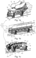
- the Figures 1a to 1c show several longitudinal section modules 1.1, 1.2, 1.3 of a modularly assembled guideway device 1, namely Figure 1a a first longitudinal section module 1.1 designed as a lower head module, Figure 1b a second longitudinal section module 1.2 designed as an intermediate module and Figure 1c a as third longitudinal section module 1.3 formed as an upper head module.
- the head modules extend beyond bends or have a bent stub.
- the longitudinal section modules 1.1, 1.2, 1.3 each have a support structure 2 with two side wall units 2.1, 2.2 extending mainly in a longitudinal direction L and cross beams 2.3 extending in a transverse direction Q.
- Each side wall unit 2.1, 2.2 in turn has a side wall 3, an upper flange 4.1 extending in the longitudinal direction L and a lower flange 4.2 extending in the longitudinal direction L.
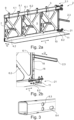
- FIG. 2a The construction of a support structure 2 or side wall unit 2.1 according to the invention for such a longitudinal section module is shown in the Figures 2a, 2b shown in detail, where in Figure 2b a detail from Figure 2a is shown.
- the side wall 3 is made of a flat material in which structural sections 6.1 and structural sections 6.2 are formed by recesses 5.
- the structural sections 6.1 divide the side wall 3 or the side wall units 2.1, 2.2 into fields.
- structural posts 7 with support elements 7.1 and the cross struts 2.3 are arranged or fastened, in particular welded, to the structural sections 6.1.
- the side wall unit 2.1 is connected to a floor unit 10.
- An upper flange 4.1 and a lower flange 4.2 are arranged on the side wall 3 as separate profiles from the side wall 3.
- the upper flange 4.1 and the lower flange 4.2 are designed in particular as rectangular hollow profiles and are connected to the side wall 3 in a manner not shown in detail, for example by welded connections.
- the connection is designed in such a way that the respective hollow profile is positioned in a defined manner relative to the side wall 3.
- the profile forming the upper chord 4.1 has first recesses 8.1 formed by means of laser cutting for receiving balustrade brackets 9. Furthermore, both the profile forming the upper chord 4.1 and the profile forming the lower chord 4.2 have first recesses 8.2 at the end, which are designed as connecting means 21 for receiving screw connections of a connecting plate 11, as shown in detail in Figure 2b
- the profiles can be connected to profiles of other longitudinal section modules 1.1, 1.2, 1.3 via the connecting plate 11.
- the longitudinal section modules 1.1, 1.2, 1.3 are shown with several components of the guideway device.
- the lower head module ( Fig. 1a ) a comb plate 12, a base 13, a balustrade 16 with a handrail 17 arranged thereon and several guides 14.1, 14.2, 14.3 for chain rollers, step/pallet rollers and/or a handrail (not shown).
- Corresponding guides 14.1, 14.2, 14.3, a base 13 and a balustrade 16 are also arranged in the intermediate module (Fig.lb).
- the guides 14.1, 14.2, 14.3 rest on the support elements 7.1.
- the upper head module ( Fig. 1c ) has, in addition to the components already present in the lower head module and/or intermediate module, a drive 15 for driving a chain and/or a handrail circuit. In the illustration of the upper head module, a balustrade 16 provided is not shown.
- the longitudinal modules 1.1, 1.2, 1.3 each have reference points 18 on the supporting structures 2, or side wall units 2.1, 2.2, or side walls 3 in the flat material, which in Fig. 2b
- the reference points 18 are designed as through holes and pass through a structural section 6.1 designed as a structural post.
- the reference points 18 are covered by mounting brackets 19, which in turn are attached to slides 20.
- the reference points 18 are formed on the flat material by laser cutting during the manufacture of the side walls 3, whereby, due to the precision typical for laser cutting, all other recesses or cutouts made in the flat material are positioned exactly opposite the reference points 18 and can therefore serve as references when positioning/aligning components.
- This circumstance also relates to any shape or recess for positioning the upper flange 4.1 and/or the lower flange 4.2 on the side wall 3.
- the first recesses 8.1, 8.2 are also positioned in a defined manner relative to the reference point 18 by the defined positioning of the hollow profiles forming the flanges 4.1, 4.2 relative to the side wall 3.
- the Reference points 18 and in particular the suspension of the longitudinal section modules 1.1, 1.2, 1.3 also enable exact alignment of the longitudinal section modules 1.1, 1.2, 1.3 to one another when they are connected to one another via the connecting means 21.
- Figure 3 further shows a profile for forming an upper chord or lower chord, which is designed as a rectangular hollow profile and has first recesses 8.3, 8.4 for receiving components of the guideway device and/or as a reference point 18.
- first recesses 8.3, 8.4 serves to receive a balustrade, a comb plate and/or a cladding element of the guideway device 1.
Landscapes
- Escalators And Moving Walkways (AREA)
Priority Applications (4)
| Application Number | Priority Date | Filing Date | Title |
|---|---|---|---|
| EP22200507.6A EP4353651A1 (fr) | 2022-10-10 | 2022-10-10 | Structure de support pour un dispositif de voie de circulation |
| EP22202864.9A EP4353664A1 (fr) | 2022-10-10 | 2022-10-20 | Dispositif de voie de circulation comportant au moins trois sections longitudinales, procédé et utilisation |
| CN202380071954.9A CN120035560A (zh) | 2022-10-10 | 2023-09-27 | 具有至少三个纵向区段的行进装置、以及方法和应用 |
| PCT/EP2023/076727 WO2024078878A1 (fr) | 2022-10-10 | 2023-09-27 | Système de guidage comprenant au moins trois sections longitudinales, procédé et utilisation |
Applications Claiming Priority (1)
| Application Number | Priority Date | Filing Date | Title |
|---|---|---|---|
| EP22200507.6A EP4353651A1 (fr) | 2022-10-10 | 2022-10-10 | Structure de support pour un dispositif de voie de circulation |
Publications (1)
| Publication Number | Publication Date |
|---|---|
| EP4353651A1 true EP4353651A1 (fr) | 2024-04-17 |
Family
ID=83689832
Family Applications (1)
| Application Number | Title | Priority Date | Filing Date |
|---|---|---|---|
| EP22200507.6A Pending EP4353651A1 (fr) | 2022-10-10 | 2022-10-10 | Structure de support pour un dispositif de voie de circulation |
Country Status (1)
| Country | Link |
|---|---|
| EP (1) | EP4353651A1 (fr) |
Citations (4)
| Publication number | Priority date | Publication date | Assignee | Title |
|---|---|---|---|---|
| EP1321424A1 (fr) | 2001-12-19 | 2003-06-25 | Inventio Ag | Charpent pour escalier mécanique |
| EP3109196A1 (fr) * | 2015-06-25 | 2016-12-28 | Thyssenkrupp Elevator Innovation Center, S.A. | Escalier roulant ou tapis roulant à treillis modulaire et procédé d'assemblage d'un escalier ou tapis roulant |
| WO2017055163A1 (fr) * | 2015-09-29 | 2017-04-06 | Inventio Ag | Procédé de montage d'une structure porteuse pour un système de transport de personnes dans un bâtiment |
| WO2022200029A1 (fr) * | 2021-03-26 | 2022-09-29 | Inventio Ag | Structure de support d'un escalier roulant ou d'un trottoir roulant |
-
2022
- 2022-10-10 EP EP22200507.6A patent/EP4353651A1/fr active Pending
Patent Citations (4)
| Publication number | Priority date | Publication date | Assignee | Title |
|---|---|---|---|---|
| EP1321424A1 (fr) | 2001-12-19 | 2003-06-25 | Inventio Ag | Charpent pour escalier mécanique |
| EP3109196A1 (fr) * | 2015-06-25 | 2016-12-28 | Thyssenkrupp Elevator Innovation Center, S.A. | Escalier roulant ou tapis roulant à treillis modulaire et procédé d'assemblage d'un escalier ou tapis roulant |
| WO2017055163A1 (fr) * | 2015-09-29 | 2017-04-06 | Inventio Ag | Procédé de montage d'une structure porteuse pour un système de transport de personnes dans un bâtiment |
| WO2022200029A1 (fr) * | 2021-03-26 | 2022-09-29 | Inventio Ag | Structure de support d'un escalier roulant ou d'un trottoir roulant |
Similar Documents
| Publication | Publication Date | Title |
|---|---|---|
| EP2900585B1 (fr) | Système de voie pour un escalier roulant ou un trottoir roulant | |
| EP4313836B1 (fr) | Structure porteuse d'un escalier roulant ou d'un tapis roulant | |
| EP2882634B1 (fr) | Structure de convoyeur aerien au-dessus d'un portique | |
| EP1321424B1 (fr) | Charpent pour escalier mécanique | |
| WO2016083151A1 (fr) | Structure portante pour un dispositif de transport | |
| EP4353651A1 (fr) | Structure de support pour un dispositif de voie de circulation | |
| EP4353650B1 (fr) | Structure de support pour un dispositif de voie de circulation | |
| WO2024078841A1 (fr) | Ensemble raccordement de module de section longitudinale et procédé d'assemblage d'appareil à chenille | |
| EP4353656A1 (fr) | Structure de support pour un dispositif de voie de circulation | |
| EP4353662A1 (fr) | Dispositif de voie de circulation comprenant une structure porteuse et des éléments de revêtement | |
| EP4353653A1 (fr) | Dispositif de réception de charge destiné à recevoir une charge sur un profilé, en particulier dans un transporteur de passagers | |
| EP4353661A1 (fr) | Socle pour dispositif de voie modulaire | |
| EP4353658B1 (fr) | Procédé d'assemblage d'un dispositif de voie modulaire et dispositif et utilisation | |
| EP4353657A1 (fr) | Dispositif de réception de charge destiné à recevoir une charge sur un profilé, en particulier dans un dispositif de voie de circulation | |
| WO2015043826A1 (fr) | Système de convoyeur aérien à monter au plafond d'une ligne de montage | |
| EP4353663A1 (fr) | Procédé de fabrication d'un composant d'un dispositif de voie de circulation | |
| EP4353652A1 (fr) | Procédé d'assemblage modulaire d'au moins un module de section longitudinale d'un dispositif de voie de circulation à assemblage modulaire, dispositif de voie de circulation | |
| EP4353654A1 (fr) | Dispositif de voie de circulation comportant au moins trois sections longitudinales, procédé et utilisation | |
| EP4353660A1 (fr) | Dispositif de voie de circulation comprenant au moins trois modules de section longitudinale avec des sections longitudinales pouvant être accouplées par complémentarité de forme ainsi que procédé d'assemblage et utilisation | |
| EP4353664A1 (fr) | Dispositif de voie de circulation comportant au moins trois sections longitudinales, procédé et utilisation | |
| WO2024078878A1 (fr) | Système de guidage comprenant au moins trois sections longitudinales, procédé et utilisation | |
| WO2024078839A1 (fr) | Système de guidage modulaire doté d'une liaison de module d'ajustement de forme/ de force, procédé et utilisation | |
| EP4551492B1 (fr) | Dispositif d'alignement pour zones d'assemblage des sections d'ossature porteuse | |
| EP3049315A1 (fr) | Système de convoyeur aérien à monter au plafond d'une ligne de montage | |
| EP3224187B1 (fr) | Construction porteuse pour un dispositif de transport |
Legal Events
| Date | Code | Title | Description |
|---|---|---|---|
| PUAI | Public reference made under article 153(3) epc to a published international application that has entered the european phase |
Free format text: ORIGINAL CODE: 0009012 |
|
| STAA | Information on the status of an ep patent application or granted ep patent |
Free format text: STATUS: THE APPLICATION HAS BEEN PUBLISHED |
|
| AK | Designated contracting states |
Kind code of ref document: A1 Designated state(s): AL AT BE BG CH CY CZ DE DK EE ES FI FR GB GR HR HU IE IS IT LI LT LU LV MC ME MK MT NL NO PL PT RO RS SE SI SK SM TR |
|
| STAA | Information on the status of an ep patent application or granted ep patent |
Free format text: STATUS: REQUEST FOR EXAMINATION WAS MADE |
|
| 17P | Request for examination filed |
Effective date: 20240508 |
|
| RBV | Designated contracting states (corrected) |
Designated state(s): AL AT BE BG CH CY CZ DE DK EE ES FI FR GB GR HR HU IE IS IT LI LT LU LV MC ME MK MT NL NO PL PT RO RS SE SI SK SM TR |