EP4353843A1 - Verfahren zur denitrifikation von geschmolzenem stahl und stahlherstellungsverfahren - Google Patents
Verfahren zur denitrifikation von geschmolzenem stahl und stahlherstellungsverfahren Download PDFInfo
- Publication number
- EP4353843A1 EP4353843A1 EP22819990.7A EP22819990A EP4353843A1 EP 4353843 A1 EP4353843 A1 EP 4353843A1 EP 22819990 A EP22819990 A EP 22819990A EP 4353843 A1 EP4353843 A1 EP 4353843A1
- Authority
- EP
- European Patent Office
- Prior art keywords
- molten steel
- slag
- denitrification
- concentration
- mass
- Prior art date
- Legal status (The legal status is an assumption and is not a legal conclusion. Google has not performed a legal analysis and makes no representation as to the accuracy of the status listed.)
- Granted
Links
Images


Classifications
-
- C—CHEMISTRY; METALLURGY
- C21—METALLURGY OF IRON
- C21C—PROCESSING OF PIG-IRON, e.g. REFINING, MANUFACTURE OF WROUGHT-IRON OR STEEL; TREATMENT IN MOLTEN STATE OF FERROUS ALLOYS
- C21C7/00—Treating molten ferrous alloys, e.g. steel, not covered by groups C21C1/00 - C21C5/00
- C21C7/10—Handling in a vacuum
-
- C—CHEMISTRY; METALLURGY
- C21—METALLURGY OF IRON
- C21C—PROCESSING OF PIG-IRON, e.g. REFINING, MANUFACTURE OF WROUGHT-IRON OR STEEL; TREATMENT IN MOLTEN STATE OF FERROUS ALLOYS
- C21C7/00—Treating molten ferrous alloys, e.g. steel, not covered by groups C21C1/00 - C21C5/00
- C21C7/04—Removing impurities by adding a treating agent
-
- C—CHEMISTRY; METALLURGY
- C21—METALLURGY OF IRON
- C21C—PROCESSING OF PIG-IRON, e.g. REFINING, MANUFACTURE OF WROUGHT-IRON OR STEEL; TREATMENT IN MOLTEN STATE OF FERROUS ALLOYS
- C21C7/00—Treating molten ferrous alloys, e.g. steel, not covered by groups C21C1/00 - C21C5/00
- C21C7/0006—Adding metallic additives
-
- C—CHEMISTRY; METALLURGY
- C21—METALLURGY OF IRON
- C21C—PROCESSING OF PIG-IRON, e.g. REFINING, MANUFACTURE OF WROUGHT-IRON OR STEEL; TREATMENT IN MOLTEN STATE OF FERROUS ALLOYS
- C21C7/00—Treating molten ferrous alloys, e.g. steel, not covered by groups C21C1/00 - C21C5/00
- C21C7/04—Removing impurities by adding a treating agent
- C21C7/06—Deoxidising, e.g. killing
-
- C—CHEMISTRY; METALLURGY
- C21—METALLURGY OF IRON
- C21C—PROCESSING OF PIG-IRON, e.g. REFINING, MANUFACTURE OF WROUGHT-IRON OR STEEL; TREATMENT IN MOLTEN STATE OF FERROUS ALLOYS
- C21C2300/00—Process aspects
- C21C2300/08—Particular sequence of the process steps
-
- Y—GENERAL TAGGING OF NEW TECHNOLOGICAL DEVELOPMENTS; GENERAL TAGGING OF CROSS-SECTIONAL TECHNOLOGIES SPANNING OVER SEVERAL SECTIONS OF THE IPC; TECHNICAL SUBJECTS COVERED BY FORMER USPC CROSS-REFERENCE ART COLLECTIONS [XRACs] AND DIGESTS
- Y02—TECHNOLOGIES OR APPLICATIONS FOR MITIGATION OR ADAPTATION AGAINST CLIMATE CHANGE
- Y02P—CLIMATE CHANGE MITIGATION TECHNOLOGIES IN THE PRODUCTION OR PROCESSING OF GOODS
- Y02P10/00—Technologies related to metal processing
- Y02P10/20—Recycling
Definitions
- the present invention relates to a method of removing nitrogen in molten steel charged in a reaction vessel, such as a ladle, by bringing the molten steel into contact with slag that is added and formed on top of the molten steel, and to a production method of steel produced by this method.
- Nitrogen is a harmful component for metal materials.
- nitrogen [N] in molten iron is removed mainly by having it adsorbed onto the surfaces of air bubbles of carbon monoxide that is generated during a decarburization process of molten pig iron. Therefore, when it comes to molten steel with a low carbon concentration, due to the limited amount of carbon monoxide to be generated, a similar technique cannot remove nitrogen to a low concentration.
- the steel production process needs to shift from a conventional method using a blast furnace or a converter to a method including melting scrap or reduced iron.
- molten iron obtained has a low carbon concentration, which may make it impossible to produce low-nitrogen steel for the above-described reason.
- Patent Literature 1 shows a method in which an Al concentration in molten steel is held at a concentration of 0.7 mass% or higher in a VOD furnace for at least five minutes to form aluminum nitride (hereinafter "AlN”) and thereby remove nitrogen.
- AlN aluminum nitride
- Patent Literature 2 shows a method in which molten steel is produced in an electric furnace using iron scrap as a main iron source, and after the molten steel is discharged into another refining vessel and held therein, denitrification flux including an Al-containing substance is added to make AlN transition to slag, and then an oxygen-containing gas is blown onto the molten steel to remove nitrogen.
- Patent Literature 3 shows a method in which molten metal is charged into a refining vessel having a gas top-blowing function, and after the surface of this molten metal is covered with slag composed mainly of CaO and Al 2 O 3 , an oxidizing gas is blown onto the surface of this covering slag to such an extent that this gas does not directly contact the molten metal to thereby remove nitrogen.
- Patent Literatures 1 and 2 which use the formation of AlN for denitrification, have a problem in that part of the AlN formed remains in the molten steel and constitutes a starting point of cracking during casting in a later step.
- Patent Literature 3 As conditions for shielding the molten steel from the oxidizing gas, the technology described in Patent Literature 3 presents the following:
- condition (1) the amount of slag increases according to the size of the vessel into which molten steel is charged.
- condition (2) specific control means and control ranges are not described, and a method for checking whether the molten steel is shielded from the gas is not clear.
- compatible conditions are ambiguous.
- the present inventors have confirmed that when a test is conducted using the same ranges as those in the compatible example described in Patent Literature 3, the denitrification speed becomes actually slow as the movement of nitrogen between the slag and the metal is restricted as a result of an increase in apparent oxygen partial pressure in the slag-metal interface due to the oxidizing gas, which makes this technology not practical for operation.
- the present invention has been contrived in view of these circumstances, and an object thereof is to propose such a molten steel denitrification method that, in performing denitrification refining of molten steel using slag, an extremely low nitrogen concentration range can be stably reached in a short time without use of a top-blown gas.
- the present invention further proposes a steel production method that uses molten steel produced by this molten steel denitrification method.
- a molten steel denitrification method that advantageously solves the above-described problems is a denitrification process in which CaO-and-Al 2 O 3 -containing slag formed by a combination of an Al addition step of adding a metal-Al-containing substance to molten steel to deoxidize and turn the molten steel into Al-containing molten steel and a CaO addition step of adding a CaO-containing substance to the molten steel is brought into contact with the Al-containing molten steel to remove nitrogen in the molten steel, characterized in that the molten steel is stirred at a stirring power density ⁇ of 60 W/t or higher.
- a steel production method according to the present invention that advantageously solves the above-described problems is characterized in that molten steel produced by any one of the above-described molten steel denitrification methods is cast after components are arbitrarily adjusted.
- nitrogen in performing denitrification refining of molten steel using slag, nitrogen can be stably removed to an extremely low nitrogen concentration range in a short time without use of a top-blown gas.
- FIG. 1 shows a device configuration suitable to implement the present invention.
- Molten steel 3 is charged into a vessel 1, such as a ladle, that is lined with a refractory 2, and slag 4 containing CaO and Al 2 O 3 is formed on top of this molten steel 3.
- a stirring inert gas 7 is blown in through a bottom-blowing nozzle 5 connected to a gas pipe 6 to give a stir.
- the stirring inert gas 7 for example, an Ar gas not including a nitrogen gas is preferable.
- a step of adding a metal-Al-containing substance to the molten steel 3 to deoxidize the molten steel 3 and turn it into Al-containing molten steel (Al addition step) and a step of adding a CaO-containing substance to the molten steel 3 (CaO addition step) may be performed using the alloy addition system 9 or may be performed in a step before entering the vacuum vessel 10.
- the step of deoxidizing the molten steel 3 (deoxidization step) may be performed separately from the Al addition step.
- the CaO addition step can be performed at an arbitrary timing. Performing the CaO addition step after the deoxidization step is preferable, because then the temperature rise of the molten steel due to the deoxidation reaction can be used for formation of slag. Performing the CaO addition step after the Al addition step is further preferable, because this can reduce deoxidization failure or variations in the slag composition due to the added Al-containing substance being hindered by the thick slag from reaching the molten steel.
- CaO-and-Al 2 O 3 -containing slag 4 Al 2 O 3 resulting from adding the CaO-containing substance and deoxidizing the molten steel is used.
- the CaO-containing substance for example, calcium aluminate that is a premelted or pre-mixed product may be used.
- the slag composition a higher slag formation rate is more advantageous for the denitrification reaction, and a mass ratio C/A between CaO and Al 2 O 3 is preferably within a range of 0.4 to 1.8 and more preferably within a range of 0.7 to 1.7.
- the form of supplying the stirring inert gas 7 into the molten steel may be, other than the above-described method, for example, a form of injecting into the molten steel through an injection lance for blowing in an inert gas.
- a first embodiment was found in the course of exploring a method for stably removing nitrogen to a low nitrogen concentration in a facility not having a gas top-blowing device.
- the CaO- and-Al 2 O 3 -containing slag 4 including MgO at a concentration of 0 to 17 mass% was formed at a ratio of 15 kg/t or higher relative to 15 kg of the molten steel 3, in such an amount that the surface of the molten steel was not recognizable to the naked eye.
- an initial nitrogen concentration [N] i in the molten steel was 50 mass ppm; the Al concentration [Al] was 0.7 mass%; the slag composition had a mass ratio C/A between CaO and Al 2 O 3 of 1.2; the MgO concentration (MgO) in the slag was 5 mass%; the molten steel temperature Tf was 1600°C; and the processing time t was 30 minutes.
- the upper limit value Max[N] f of variations in the achieved nitrogen concentration remained stable up to an atmospheric pressure P of 1.0 ⁇ 10 5 Pa.
- a preferable atmospheric pressure P is specified as 1.0 ⁇ 10 5 Pa or lower, and it is further preferably 0.7 ⁇ 10 5 Pa or lower.
- a molten steel denitrification method that is a denitrification process in which CaO-and-Al 2 O 3 -containing slag formed by a combination of an Al addition step of adding a metal-Al-containing substance to molten steel to deoxidize and turn the molten steel into Al-containing molten steel and a CaO addition step of adding a CaO-containing substance to the molten steel is brought into contact with the Al-containing molten steel to remove nitrogen in the molten steel, in which the molten steel is stirred at a stirring power density ⁇ of 60 W/t or higher, or a molten steel denitrification method in which, further, in the denitrification process, the surface of the molten
- the stirring power density ⁇ is not particularly limited, the bottom-blown gas, when blown in in a large amount, will be blown through without being effectively used; therefore, with about 5000 W/t as the upper limit, the stirring power density ⁇ should be appropriately set within such a range that possible troubles accompanying its rise (e.g., sculls adhering to a furnace lid) do not occur.
- the lower limit of the furnace atmospheric pressure P is preferably about 10 3 Pa.
- a second embodiment was found in the course of studying the influence of the MgO concentration (MgO) in the CaO-and-Al 2 O 3 -containing slag.
- a denitrification test was conducted in which the MgO concentration (MgO) in the slag was varied from 0 to 17 mass% while the stirring power density ⁇ was held constant at 500 W/t, with the furnace atmospheric pressure P being 0.7 ⁇ 10 5 Pa and the initial nitrogen concentration [N] i , the Al concentration [Al], the C/A in the slag composition, the molten steel temperature Tf, and the processing time t being the same as those mentioned above.
- the furnace atmospheric pressure P being 0.7 ⁇ 10 5 Pa
- the initial nitrogen concentration [N] i the initial nitrogen concentration [N] i
- the Al concentration [Al] the C/A in the slag composition
- the molten steel temperature Tf the processing time t being the same as those mentioned above.
- a molten steel temperature after the denitrification process is used as the molten steel temperature Tf, and that the denitrification process is completed at 1600°C or higher, although it depends on a casting step that is a later step and a transfer time.
- the lower limit of the MgO concentration (MgO) in the slag is not particularly limited, it may be 0 mass%.
- a third embodiment was found in the course of exploring improvement measures for a decrease in the denitrification speed in the case where it is unavoidable to increase the MgO concentration from the viewpoint of protecting the refractory of the vessel into which the molten steel is charged.
- T f molten steel temperature
- the molten steel temperature T f needed to be raised by about 5°C.
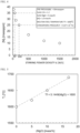
- the furnace atmospheric pressure P was 4 ⁇ 10 3 Pa; the Al concentration [Al] was 0.7 mass%; the initial nitrogen concentration [N] i was 50 mass ppm; the C/A in the slag composition was 1.2; the stirring power density ⁇ was 60 W/t; and the processing time t was 30 minutes.
- This study has quantitatively revealed the amount of increase in the molten steel temperature that can compensate for a decrease in the denitrification reaction due to an increase in the MgO concentration.
- the third embodiment i.e., a molten steel denitrification method in which, in addition to the first embodiment, the temperature of the molten steel is increased by 5°C or more at each time when the MgO concentration (MgO) in the slag increases by 1.0 mass% beyond 5.0 mass%.
- MgO MgO concentration
- Patent Literature 3 requires an Al concentration [Al] in molten steel of 0.3 mass% to 2 mass% as a concentration needed to increase the ratio of nitrogen distribution between slag and metal, which makes it costly to produce ordinary steel.
- a fourth embodiment was found in the course of exploring the possibilities of removing nitrogen with the Al concentration [Al] in the molten steel reduced to a lower concentration to solve this problem.
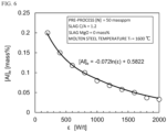
- the minimum required Al concentration [Al] e for reducing nitrogen in molten steel to 25 mass ppm using the aforementioned small-sized high-frequency vacuum induction melting furnace it was found that, as shown in FIG. 6 , the required Al concentration [Al] e (mass%) varied according to the stirring power density ⁇ (W/t).
- the MgO concentration (MgO) in the slag was 0 mass% and the molten steel temperature Tf was 1600°C, and the initial nitrogen concentration [N] i and the C/A in the slag composition were the same as those mentioned above.
- the furnace atmospheric pressure P was 0.7 ⁇ 10 5 Pa; the stirring power density ⁇ was controlled so as to remain constant within a range of 200 to 2000 W/t during the process; and the processing time t was 30 minutes.
- the third embodiment i.e., a molten steel denitrification method in which, in addition to any one of the first to third embodiments, in the Al addition step, the Al concentration [Al] (mass%) in the molten steel is set to be equal to or higher than a value [Al] e calculated by the following Formula (A) based on the stirring power density ⁇ (W/t) during the denitrification process.
- Al e ⁇ 0.072 ⁇ ln ⁇ + 0.5822
- molten steel produced by the above-described molten steel denitrification method is cast after additionally it is adjusted to a predetermined composition and form control and floating separation of inclusions are performed as necessary. It is possible to produce high-grade steel which is low-nitrogen steel and of which various components have been adjusted.
- Table 1 shows the test conditions and the results.
- processes No. 1 to 4 in which the stirring power density ⁇ is sufficient the results were favorable with the post-process N concentration [N] f at 35 mass ppm or lower.
- nitrogen was not sufficiently removed in the same processing time t.
- the molten steel denitrification method according to the present invention can stably mass-produce low-nitrogen steel.
- this method contributes to reducing CO 2 and is industrially useful.
Landscapes
- Chemical & Material Sciences (AREA)
- Engineering & Computer Science (AREA)
- Materials Engineering (AREA)
- Metallurgy (AREA)
- Organic Chemistry (AREA)
- Treatment Of Steel In Its Molten State (AREA)
Applications Claiming Priority (2)
| Application Number | Priority Date | Filing Date | Title |
|---|---|---|---|
| JP2021098131A JP7480751B2 (ja) | 2021-06-11 | 2021-06-11 | 溶鋼の脱窒方法および鋼の製造方法 |
| PCT/JP2022/020009 WO2022259806A1 (ja) | 2021-06-11 | 2022-05-12 | 溶鋼の脱窒方法および鋼の製造方法 |
Publications (3)
| Publication Number | Publication Date |
|---|---|
| EP4353843A1 true EP4353843A1 (de) | 2024-04-17 |
| EP4353843A4 EP4353843A4 (de) | 2024-08-21 |
| EP4353843B1 EP4353843B1 (de) | 2025-10-29 |
Family
ID=84424857
Family Applications (1)
| Application Number | Title | Priority Date | Filing Date |
|---|---|---|---|
| EP22819990.7A Active EP4353843B1 (de) | 2021-06-11 | 2022-05-12 | Verfahren zur denitrifikation von geschmolzenem stahl und stahlherstellungsverfahren |
Country Status (10)
| Country | Link |
|---|---|
| US (1) | US12252754B2 (de) |
| EP (1) | EP4353843B1 (de) |
| JP (1) | JP7480751B2 (de) |
| KR (1) | KR20240004778A (de) |
| CN (1) | CN117460846A (de) |
| BR (1) | BR112023025857A2 (de) |
| CA (1) | CA3218994A1 (de) |
| MX (1) | MX2023014736A (de) |
| TW (1) | TWI828175B (de) |
| WO (1) | WO2022259806A1 (de) |
Families Citing this family (2)
| Publication number | Priority date | Publication date | Assignee | Title |
|---|---|---|---|---|
| WO2026004831A1 (ja) * | 2024-06-28 | 2026-01-02 | Jfeスチール株式会社 | 無方向性電磁鋼板用スラブの製造方法 |
| WO2026004825A1 (ja) * | 2024-06-28 | 2026-01-02 | Jfeスチール株式会社 | 無方向性電磁鋼板用スラブの製造方法 |
Family Cites Families (46)
| Publication number | Priority date | Publication date | Assignee | Title |
|---|---|---|---|---|
| SU541871A1 (ru) | 1975-05-21 | 1977-01-05 | Предприятие П/Я А-7653 | Шлак дл рафинировани стали |
| SU1002370A1 (ru) | 1981-10-05 | 1983-03-07 | Московский Ордена Трудового Красного Знамени И Ордена Октябрьской Революции Институт Стали И Сплавов | Способ рафинировани нержавеющей стали |
| SU1090724A1 (ru) | 1982-12-30 | 1984-05-07 | Московский Ордена Октябрьской Революции И Ордена Трудового Красного Знамени Институт Стали И Сплавов | Способ выплавки стали с низким содержанием азота (его варианты) |
| JPS61272313A (ja) | 1985-05-29 | 1986-12-02 | Nippon Kokan Kk <Nkk> | 真空精錬による溶鋼の脱窒方法 |
| US4586956A (en) | 1985-07-17 | 1986-05-06 | Labate M D | Method and agents for producing clean steel |
| JPS62164816A (ja) | 1986-01-17 | 1987-07-21 | Nippon Steel Corp | 溶鋼の処理方法 |
| SU1402621A1 (ru) | 1986-08-01 | 1988-06-15 | Новолипецкий металлургический комбинат им.Ю.В.Андропова | Способ производства низкоуглеродистой,низкокремнистой,малоазотистой легированной алюминием стали |
| JPS6442516A (en) | 1987-08-07 | 1989-02-14 | Mitsui Shipbuilding Eng | Method for denitriding, desulfurizing, and deoxidizing fe-base, co-base, or ni-base alloy |
| RU2002816C1 (ru) | 1991-07-29 | 1993-11-15 | Череповецкий металлургический комбинат | Способ дегазации и десульфурации нержавеющей стали |
| JPH05320733A (ja) | 1991-12-27 | 1993-12-03 | Sumitomo Metal Ind Ltd | ステンレス溶鋼の脱窒方法 |
| JPH06212244A (ja) * | 1993-01-13 | 1994-08-02 | Nippon Steel Corp | 極低窒素鋼の溶製方法 |
| JPH07224315A (ja) * | 1993-12-17 | 1995-08-22 | Kawasaki Steel Corp | 溶鉄の脱窒方法 |
| JP3333795B2 (ja) | 1995-03-03 | 2002-10-15 | 川崎製鉄株式会社 | 溶融金属の脱窒方法および脱窒・脱炭方法 |
| JP3319244B2 (ja) * | 1995-09-29 | 2002-08-26 | 住友金属工業株式会社 | 溶鋼の昇熱精錬方法 |
| KR100207859B1 (ko) | 1995-11-11 | 1999-07-15 | 이구택 | 정련용 슬래그 조제방법 |
| JPH09165615A (ja) | 1995-12-14 | 1997-06-24 | Kawasaki Steel Corp | 溶融金属の脱窒方法 |
| DE69716582T2 (de) | 1996-11-20 | 2003-06-12 | Nippon Steel Corp., Tokio/Tokyo | Verfahren und vorrichtung zur vakuum-entkohlung/feinung von flüssigem stahl |
| JP3473388B2 (ja) * | 1998-03-27 | 2003-12-02 | Jfeスチール株式会社 | ステンレス溶鋼の精錬方法 |
| JP3885387B2 (ja) | 1998-10-20 | 2007-02-21 | Jfeスチール株式会社 | 清浄性に優れた極低硫鋼の製造方法 |
| JP3752892B2 (ja) | 1999-05-31 | 2006-03-08 | Jfeスチール株式会社 | 溶鋼へのチタンの添加方法 |
| KR100584726B1 (ko) | 1999-12-21 | 2006-05-30 | 주식회사 포스코 | Si탈산강용 턴디쉬플럭스의 제조방법 |
| RU2171296C1 (ru) | 2000-12-13 | 2001-07-27 | Пономаренко Дмитрий Александрович | Способ обработки стали |
| JP3918568B2 (ja) | 2001-03-16 | 2007-05-23 | Jfeスチール株式会社 | 極低硫鋼の製造方法 |
| JP4079097B2 (ja) | 2004-02-19 | 2008-04-23 | Jfeスチール株式会社 | 高清浄鋼の溶製方法 |
| JP4079190B2 (ja) | 2005-12-27 | 2008-04-23 | 吉澤石灰工業株式会社 | 低窒素、低酸素および低イオウの鋼を製錬するためのフラックス |
| JP5092245B2 (ja) | 2006-02-09 | 2012-12-05 | Jfeスチール株式会社 | 溶鋼の脱窒方法 |
| JP2008240126A (ja) | 2007-03-28 | 2008-10-09 | Jfe Steel Kk | ステンレス溶鋼の精錬方法 |
| JP5262075B2 (ja) | 2007-11-14 | 2013-08-14 | 新日鐵住金株式会社 | 耐サワー性能に優れた鋼管用鋼の製造方法 |
| KR100922061B1 (ko) | 2007-12-12 | 2009-10-16 | 주식회사 포스코 | 극저탄소 페라이트계 스테인리스강 제조방법 |
| RU2378391C1 (ru) | 2008-05-15 | 2010-01-10 | Открытое акционерное общество "Магнитогорский металлургический комбинат" | Способ получения высокоуглеродистой стали кордового качества |
| BR112012030096B1 (pt) | 2010-06-08 | 2018-06-19 | Nippon Steel & Sumitomo Metal Corporation | Aço para tubo de aço com excelente resistência ao craqueamento sob tensão por sulfeto |
| KR101198486B1 (ko) | 2010-12-24 | 2012-11-06 | 주식회사 포스코 | 티타늄 함유 오스테나이트계 스테인리스강의 제조방법 및 이를 이용하여 제조된 티타늄 함유 오스테나이트계 스테인리스강 |
| US8523977B2 (en) | 2011-01-14 | 2013-09-03 | Nucor Corporation | Method of desulfurizing steel |
| JP5979029B2 (ja) | 2013-02-04 | 2016-08-24 | 新日鐵住金株式会社 | 極低硫低窒素鋼の製造方法 |
| JP6020414B2 (ja) | 2013-11-01 | 2016-11-02 | Jfeスチール株式会社 | アルミニウム含有ステンレス鋼の精錬方法 |
| CN104073602B (zh) | 2014-06-27 | 2017-01-18 | 攀钢集团攀枝花钢铁研究院有限公司 | 一种脱氮剂及其制备方法和rh脱氮的方法 |
| CN108396094A (zh) | 2017-02-05 | 2018-08-14 | 鞍钢股份有限公司 | 一种低氮低碳钢的冶炼方法 |
| WO2018216660A1 (ja) | 2017-05-25 | 2018-11-29 | Jfeスチール株式会社 | 高マンガン鋼の溶製方法 |
| TWI698532B (zh) | 2018-04-17 | 2020-07-11 | 日商日本製鐵股份有限公司 | 鋼液的製造方法 |
| CN109252008B (zh) * | 2018-10-10 | 2020-08-07 | 新疆八一钢铁股份有限公司 | 一种低碳低氮超低硫钢的生产方法 |
| JP7265136B2 (ja) | 2019-04-25 | 2023-04-26 | 日本製鉄株式会社 | 極低窒素鋼の溶製方法 |
| RU2740949C1 (ru) | 2019-07-22 | 2021-01-21 | Сергей Анатольевич Ботников | Способ получения суперчистой стали, раскисленной алюминием, для производства высококачественной металлопродукции |
| JP7126096B2 (ja) | 2019-10-08 | 2022-08-26 | Jfeスチール株式会社 | 極低硫ステンレス鋼の製造方法 |
| CN112442575A (zh) | 2020-10-29 | 2021-03-05 | 任志峰 | 一种超低碳不锈钢的rh真空精炼方法 |
| CN112813228A (zh) | 2020-12-30 | 2021-05-18 | 河北震刚能源科技研发有限公司 | 一种多功能炼钢用预熔渣精炼剂及其制备方法 |
| JP7211454B2 (ja) | 2021-06-11 | 2023-01-24 | Jfeスチール株式会社 | 溶鋼の脱窒方法、脱窒及び脱硫同時処理方法および鋼の製造方法 |
-
2021
- 2021-06-11 JP JP2021098131A patent/JP7480751B2/ja active Active
-
2022
- 2022-05-12 CN CN202280041131.7A patent/CN117460846A/zh active Pending
- 2022-05-12 MX MX2023014736A patent/MX2023014736A/es unknown
- 2022-05-12 WO PCT/JP2022/020009 patent/WO2022259806A1/ja not_active Ceased
- 2022-05-12 US US18/560,737 patent/US12252754B2/en active Active
- 2022-05-12 KR KR1020237041299A patent/KR20240004778A/ko active Pending
- 2022-05-12 EP EP22819990.7A patent/EP4353843B1/de active Active
- 2022-05-12 BR BR112023025857A patent/BR112023025857A2/pt active IP Right Grant
- 2022-05-12 CA CA3218994A patent/CA3218994A1/en active Pending
- 2022-06-02 TW TW111120536A patent/TWI828175B/zh active
Also Published As
| Publication number | Publication date |
|---|---|
| CN117460846A (zh) | 2024-01-26 |
| EP4353843A4 (de) | 2024-08-21 |
| MX2023014736A (es) | 2024-01-16 |
| KR20240004778A (ko) | 2024-01-11 |
| WO2022259806A1 (ja) | 2022-12-15 |
| BR112023025857A2 (pt) | 2024-02-27 |
| US12252754B2 (en) | 2025-03-18 |
| JP2022189514A (ja) | 2022-12-22 |
| US20240247329A1 (en) | 2024-07-25 |
| EP4353843B1 (de) | 2025-10-29 |
| TWI828175B (zh) | 2024-01-01 |
| JP7480751B2 (ja) | 2024-05-10 |
| CA3218994A1 (en) | 2022-12-15 |
| TW202313993A (zh) | 2023-04-01 |
Similar Documents
| Publication | Publication Date | Title |
|---|---|---|
| JP5092245B2 (ja) | 溶鋼の脱窒方法 | |
| EP4353845B1 (de) | Verfahren zur denitrifikation von geschmolzenem stahl, verfahren zur gleichzeitigen denitrifikation und entschwefelungsbehandlung sowie stahlherstellungsverfahren | |
| JP5910579B2 (ja) | 極低窒素純鉄の溶製方法 | |
| EP4353843A1 (de) | Verfahren zur denitrifikation von geschmolzenem stahl und stahlherstellungsverfahren | |
| JP3428628B2 (ja) | ステンレス鋼の脱硫精錬方法 | |
| EP4353842B1 (de) | Verfahren zur denitrifikation von geschmolzenem stahl und stahlherstellungsverfahren | |
| EP4353844B1 (de) | Verfahren zum sekundären raffinieren von geschmolzenem stahl und verfahren zur herstellung von stahl | |
| JP2776118B2 (ja) | 無方向性電磁鋼板材の溶製方法 | |
| JP7318822B2 (ja) | 溶鋼の処理方法および鋼の製造方法 | |
| JP4765374B2 (ja) | 含クロム溶銑の脱硫処理方法 | |
| RU2838231C2 (ru) | Способ удаления азота из расплавленной стали и способ производства стали | |
| JP7319548B2 (ja) | 溶鋼の脱硫方法 | |
| JPH111714A (ja) | 製鋼方法 | |
| JP2002327208A (ja) | 鋼の溶製方法 | |
| JP3893769B2 (ja) | 高Al含有ステンレス鋼の精錬方法 | |
| JP2001107132A (ja) | ステンレス鋼の脱窒方法 | |
| JPH08260021A (ja) | 高純度高Ni鋼の製造方法 | |
| JPH01116024A (ja) | 溶鋼処理方法 |
Legal Events
| Date | Code | Title | Description |
|---|---|---|---|
| STAA | Information on the status of an ep patent application or granted ep patent |
Free format text: STATUS: THE INTERNATIONAL PUBLICATION HAS BEEN MADE |
|
| PUAI | Public reference made under article 153(3) epc to a published international application that has entered the european phase |
Free format text: ORIGINAL CODE: 0009012 |
|
| STAA | Information on the status of an ep patent application or granted ep patent |
Free format text: STATUS: REQUEST FOR EXAMINATION WAS MADE |
|
| 17P | Request for examination filed |
Effective date: 20231220 |
|
| AK | Designated contracting states |
Kind code of ref document: A1 Designated state(s): AL AT BE BG CH CY CZ DE DK EE ES FI FR GB GR HR HU IE IS IT LI LT LU LV MC MK MT NL NO PL PT RO RS SE SI SK SM TR |
|
| A4 | Supplementary search report drawn up and despatched |
Effective date: 20240718 |
|
| RIC1 | Information provided on ipc code assigned before grant |
Ipc: C21C 7/06 20060101ALI20240712BHEP Ipc: C21C 7/04 20060101ALI20240712BHEP Ipc: C21C 7/10 20060101ALI20240712BHEP Ipc: C21C 7/00 20060101AFI20240712BHEP |
|
| DAV | Request for validation of the european patent (deleted) | ||
| DAX | Request for extension of the european patent (deleted) | ||
| RIC1 | Information provided on ipc code assigned before grant |
Ipc: C21C 7/06 20060101ALI20250501BHEP Ipc: C21C 7/04 20060101ALI20250501BHEP Ipc: C21C 7/10 20060101ALI20250501BHEP Ipc: C21C 7/00 20060101AFI20250501BHEP |
|
| GRAP | Despatch of communication of intention to grant a patent |
Free format text: ORIGINAL CODE: EPIDOSNIGR1 |
|
| STAA | Information on the status of an ep patent application or granted ep patent |
Free format text: STATUS: GRANT OF PATENT IS INTENDED |
|
| INTG | Intention to grant announced |
Effective date: 20250616 |
|
| GRAS | Grant fee paid |
Free format text: ORIGINAL CODE: EPIDOSNIGR3 |
|
| GRAA | (expected) grant |
Free format text: ORIGINAL CODE: 0009210 |
|
| STAA | Information on the status of an ep patent application or granted ep patent |
Free format text: STATUS: THE PATENT HAS BEEN GRANTED |
|
| AK | Designated contracting states |
Kind code of ref document: B1 Designated state(s): AL AT BE BG CH CY CZ DE DK EE ES FI FR GB GR HR HU IE IS IT LI LT LU LV MC MK MT NL NO PL PT RO RS SE SI SK SM TR |
|
| REG | Reference to a national code |
Ref country code: CH Ref legal event code: F10 Free format text: ST27 STATUS EVENT CODE: U-0-0-F10-F00 (AS PROVIDED BY THE NATIONAL OFFICE) Effective date: 20251029 Ref country code: GB Ref legal event code: FG4D |
|
| REG | Reference to a national code |
Ref country code: DE Ref legal event code: R096 Ref document number: 602022024102 Country of ref document: DE |
|
| REG | Reference to a national code |
Ref country code: IE Ref legal event code: FG4D |
|
| REG | Reference to a national code |
Ref country code: NL Ref legal event code: MP Effective date: 20251029 |
|
| PG25 | Lapsed in a contracting state [announced via postgrant information from national office to epo] |
Ref country code: ES Free format text: LAPSE BECAUSE OF FAILURE TO SUBMIT A TRANSLATION OF THE DESCRIPTION OR TO PAY THE FEE WITHIN THE PRESCRIBED TIME-LIMIT Effective date: 20251029 |
|
| REG | Reference to a national code |
Ref country code: LT Ref legal event code: MG9D |
|
| PG25 | Lapsed in a contracting state [announced via postgrant information from national office to epo] |
Ref country code: NO Free format text: LAPSE BECAUSE OF FAILURE TO SUBMIT A TRANSLATION OF THE DESCRIPTION OR TO PAY THE FEE WITHIN THE PRESCRIBED TIME-LIMIT Effective date: 20260129 |
|
| PG25 | Lapsed in a contracting state [announced via postgrant information from national office to epo] |
Ref country code: HR Free format text: LAPSE BECAUSE OF FAILURE TO SUBMIT A TRANSLATION OF THE DESCRIPTION OR TO PAY THE FEE WITHIN THE PRESCRIBED TIME-LIMIT Effective date: 20251029 Ref country code: AT Free format text: LAPSE BECAUSE OF FAILURE TO SUBMIT A TRANSLATION OF THE DESCRIPTION OR TO PAY THE FEE WITHIN THE PRESCRIBED TIME-LIMIT Effective date: 20251029 Ref country code: FI Free format text: LAPSE BECAUSE OF FAILURE TO SUBMIT A TRANSLATION OF THE DESCRIPTION OR TO PAY THE FEE WITHIN THE PRESCRIBED TIME-LIMIT Effective date: 20251029 |
|
| REG | Reference to a national code |
Ref country code: AT Ref legal event code: MK05 Ref document number: 1851618 Country of ref document: AT Kind code of ref document: T Effective date: 20251029 |
|
| PG25 | Lapsed in a contracting state [announced via postgrant information from national office to epo] |
Ref country code: NL Free format text: LAPSE BECAUSE OF FAILURE TO SUBMIT A TRANSLATION OF THE DESCRIPTION OR TO PAY THE FEE WITHIN THE PRESCRIBED TIME-LIMIT Effective date: 20251029 |
|
| PG25 | Lapsed in a contracting state [announced via postgrant information from national office to epo] |
Ref country code: RS Free format text: LAPSE BECAUSE OF FAILURE TO SUBMIT A TRANSLATION OF THE DESCRIPTION OR TO PAY THE FEE WITHIN THE PRESCRIBED TIME-LIMIT Effective date: 20260129 |
|
| PG25 | Lapsed in a contracting state [announced via postgrant information from national office to epo] |
Ref country code: IS Free format text: LAPSE BECAUSE OF FAILURE TO SUBMIT A TRANSLATION OF THE DESCRIPTION OR TO PAY THE FEE WITHIN THE PRESCRIBED TIME-LIMIT Effective date: 20260228 |
|
| PG25 | Lapsed in a contracting state [announced via postgrant information from national office to epo] |
Ref country code: PT Free format text: LAPSE BECAUSE OF FAILURE TO SUBMIT A TRANSLATION OF THE DESCRIPTION OR TO PAY THE FEE WITHIN THE PRESCRIBED TIME-LIMIT Effective date: 20260302 |
|
| PG25 | Lapsed in a contracting state [announced via postgrant information from national office to epo] |
Ref country code: PL Free format text: LAPSE BECAUSE OF FAILURE TO SUBMIT A TRANSLATION OF THE DESCRIPTION OR TO PAY THE FEE WITHIN THE PRESCRIBED TIME-LIMIT Effective date: 20251029 |
|
| PG25 | Lapsed in a contracting state [announced via postgrant information from national office to epo] |
Ref country code: LV Free format text: LAPSE BECAUSE OF FAILURE TO SUBMIT A TRANSLATION OF THE DESCRIPTION OR TO PAY THE FEE WITHIN THE PRESCRIBED TIME-LIMIT Effective date: 20251029 |