EP4353905B1 - Engin de chantier, notamment finisseur ou rouleau tandem - Google Patents
Engin de chantier, notamment finisseur ou rouleau tandem Download PDFInfo
- Publication number
- EP4353905B1 EP4353905B1 EP23202751.6A EP23202751A EP4353905B1 EP 4353905 B1 EP4353905 B1 EP 4353905B1 EP 23202751 A EP23202751 A EP 23202751A EP 4353905 B1 EP4353905 B1 EP 4353905B1
- Authority
- EP
- European Patent Office
- Prior art keywords
- seat
- operator
- driver
- construction machine
- support structure
- Prior art date
- Legal status (The legal status is an assumption and is not a legal conclusion. Google has not performed a legal analysis and makes no representation as to the accuracy of the status listed.)
- Active
Links
Images




Classifications
-
- E—FIXED CONSTRUCTIONS
- E01—CONSTRUCTION OF ROADS, RAILWAYS, OR BRIDGES
- E01C—CONSTRUCTION OF, OR SURFACES FOR, ROADS, SPORTS GROUNDS, OR THE LIKE; MACHINES OR AUXILIARY TOOLS FOR CONSTRUCTION OR REPAIR
- E01C19/00—Machines, tools or auxiliary devices for preparing or distributing paving materials, for working the placed materials, or for forming, consolidating, or finishing the paving
- E01C19/48—Machines, tools or auxiliary devices for preparing or distributing paving materials, for working the placed materials, or for forming, consolidating, or finishing the paving for laying-down the materials and consolidating them, or finishing the surface, e.g. slip forms therefor, forming kerbs or gutters in a continuous operation in situ
- E01C19/4833—Machines, tools or auxiliary devices for preparing or distributing paving materials, for working the placed materials, or for forming, consolidating, or finishing the paving for laying-down the materials and consolidating them, or finishing the surface, e.g. slip forms therefor, forming kerbs or gutters in a continuous operation in situ with tamping or vibrating means for consolidating or finishing, e.g. immersed vibrators, with or without non-vibratory or non-percussive pressing or smoothing means
- E01C19/4853—Apparatus designed for railless operation, e.g. crawler-mounted, provided with portable trackway arrangements
-
- E—FIXED CONSTRUCTIONS
- E01—CONSTRUCTION OF ROADS, RAILWAYS, OR BRIDGES
- E01C—CONSTRUCTION OF, OR SURFACES FOR, ROADS, SPORTS GROUNDS, OR THE LIKE; MACHINES OR AUXILIARY TOOLS FOR CONSTRUCTION OR REPAIR
- E01C19/00—Machines, tools or auxiliary devices for preparing or distributing paving materials, for working the placed materials, or for forming, consolidating, or finishing the paving
- E01C19/22—Machines, tools or auxiliary devices for preparing or distributing paving materials, for working the placed materials, or for forming, consolidating, or finishing the paving for consolidating or finishing laid-down unset materials
- E01C19/23—Rollers therefor; Such rollers usable also for compacting soil
- E01C19/26—Rollers therefor; Such rollers usable also for compacting soil self-propelled or fitted to road vehicles
-
- E—FIXED CONSTRUCTIONS
- E01—CONSTRUCTION OF ROADS, RAILWAYS, OR BRIDGES
- E01C—CONSTRUCTION OF, OR SURFACES FOR, ROADS, SPORTS GROUNDS, OR THE LIKE; MACHINES OR AUXILIARY TOOLS FOR CONSTRUCTION OR REPAIR
- E01C19/00—Machines, tools or auxiliary devices for preparing or distributing paving materials, for working the placed materials, or for forming, consolidating, or finishing the paving
- E01C19/22—Machines, tools or auxiliary devices for preparing or distributing paving materials, for working the placed materials, or for forming, consolidating, or finishing the paving for consolidating or finishing laid-down unset materials
- E01C19/23—Rollers therefor; Such rollers usable also for compacting soil
-
- E—FIXED CONSTRUCTIONS
- E01—CONSTRUCTION OF ROADS, RAILWAYS, OR BRIDGES
- E01C—CONSTRUCTION OF, OR SURFACES FOR, ROADS, SPORTS GROUNDS, OR THE LIKE; MACHINES OR AUXILIARY TOOLS FOR CONSTRUCTION OR REPAIR
- E01C19/00—Machines, tools or auxiliary devices for preparing or distributing paving materials, for working the placed materials, or for forming, consolidating, or finishing the paving
- E01C19/48—Machines, tools or auxiliary devices for preparing or distributing paving materials, for working the placed materials, or for forming, consolidating, or finishing the paving for laying-down the materials and consolidating them, or finishing the surface, e.g. slip forms therefor, forming kerbs or gutters in a continuous operation in situ
-
- E—FIXED CONSTRUCTIONS
- E01—CONSTRUCTION OF ROADS, RAILWAYS, OR BRIDGES
- E01C—CONSTRUCTION OF, OR SURFACES FOR, ROADS, SPORTS GROUNDS, OR THE LIKE; MACHINES OR AUXILIARY TOOLS FOR CONSTRUCTION OR REPAIR
- E01C2301/00—Machine characteristics, parts or accessories not otherwise provided for
- E01C2301/30—Cabin details
-
- E—FIXED CONSTRUCTIONS
- E01—CONSTRUCTION OF ROADS, RAILWAYS, OR BRIDGES
- E01C—CONSTRUCTION OF, OR SURFACES FOR, ROADS, SPORTS GROUNDS, OR THE LIKE; MACHINES OR AUXILIARY TOOLS FOR CONSTRUCTION OR REPAIR
- E01C2301/00—Machine characteristics, parts or accessories not otherwise provided for
- E01C2301/40—Working platform or walkway
Definitions
- the invention relates to a construction machine, in particular a road paver or a tandem roller.
- Construction machines of this type are used, for example, in road and path construction, in the construction of squares and runways.
- a construction machine typically comprises a machine frame, a driver's cab, at least one driving device, and an operating unit.
- a construction machine of this type is a road paver or a tandem roller.
- a road paver typically further comprises a material hopper positioned in front of the driver's cab in the paving direction, conveyor devices for the longitudinal and transverse conveyance of paving material, and a paving screed.
- Tandem rollers typically have so-called roller drums as driving devices. Tandem rollers can be pivot-steered or articulated.
- Such construction machines are usually self-propelled construction machines that have a drive motor, for example an internal combustion engine or an electric motor, which provides the drive energy required for operation of the construction machine.
- the supporting structure of the construction machine is typically a machine frame and a chassis supporting the machine frame and having at least one driving device, for example a wheel, a track drive, or a compaction/rolling drum.
- Construction machinery is typically operated from a control station on the construction machine.
- the control station has suitable operating devices.
- the control station can have at least one control station door.
- the control station door can be adjustable, in particular pivotable, between a closed and an at least partially open position.
- the control station door essentially represents a fall protection device and can, for example, be part of a railing structure. It can be provided that the control station must be entered through the control station door. This can be the case in particular with tandem rollers. However, it is also possible that opening the control station door is not necessary to enter the control station, as another access point is available, for example, from the rear of the construction machine, as is often the case with road pavers.
- the control station can, for example, be open, have at least one roof arranged above the control station, or be designed in the form of a cabin that completely encloses the control station.
- Road pavers are used to apply a surface layer of paving material, such as asphalt or concrete, to a prepared subsoil or to install.
- paving material such as asphalt or concrete
- they have a material hopper at their front end in which paving material is stored. This is transported through a central shaft to the rear of the machine and there distributed transversely to the working direction by a transverse distribution device, for example a screw conveyor. Finally, the paving material is smoothed off by a paving screed and pre-compacted.
- a typical road paver for example, is in the DE102017002225A1 revealed.
- Tandem rollers are usually used either to compact the subsoil on which a surface course is to be laid, or to compact a layer of paving material, in particular asphalt.
- tandem rollers can be used in a paving train following a road paver in the paving direction and compact the asphalt mat laid out by the paver.
- tandem rollers typically have two compaction drums, which can essentially consist of hollow metal cylinders with which the tandem roller rolls on the soil to be compacted.
- at least one vibration exciter can be arranged, which causes the compaction drum to vibrate in order to influence the compaction.
- a typical tandem roller can be found, for example, in the DE102018007825A1 revealed.
- Construction machines of this type also have at least one control unit.
- an control unit is understood to be a unit consisting of a driver's seat for the driver of the construction machine and the control elements used by the driver to control the construction machine.
- the control elements can, for example, be part of a so-called control console.
- An control console refers in particular to a type of panel-like arrangement of several control elements.
- the driver's seat and the control console are typically movably mounted in the operator's station to allow the driver to adopt different seating positions within the operator's station. This can improve operating comfort and the driver's overview of the work area and the external environment of the construction machine, which increases both the accuracy of the work and operational safety.
- control unit in this case also includes structures that connect the driver's seat to the control console or contribute to its movable mounting.
- this also includes, for example, a support structure on which both the driver's seat and the control console are arranged. It is known to provide a transverse guide with at least one guide rail along which the control unit can be displaced.
- the support structure can be movably mounted on the at least one guide rail, so that the support structure, together with the driver's seat and the control console, is designed to be movable along the at least one guide rail.
- driver's seat and the control console it is known to design the driver's seat and the control console to be displaceable together in a direction transverse to the working direction of the construction machine within the operator's station.
- a working direction In this case, this is understood in particular as a front/rear direction of the construction machine.
- driver seats or control units that can be moved transversely to the working direction of the construction machine are known, for example, from the patents DE 10 2010 035 270 B4 and EP 1 961 607 B1 known to the applicant.
- DE 10 2010 035 270 B4 discloses a driver's seat which, together with the control console and steering wheel, is mounted on a rail by means of a supporting structure and can be moved transversely.
- US 2017/088103 A1 discloses a control station with a seat support on which a driver's seat and an operating console are arranged. Using the seat support, the driver's seat and the operating console can be moved together along a guide rail. The driver's seat is mounted so it can rotate around a vertical axis.
- the driver's seat preferably has a so-called seat index point.
- the seat index point is a standard defined in the EN ISO 5353 standard.
- the EN ISO 5353 standard is hereby incorporated by reference.
- the seat index point is determined using the determination device described in this standard.
- the seat index point of the driver's seat is therefore approximately located at the intersection point of a theoretical axis of the upper body of a person sitting in the driver's seat with the theoretical axis of the thigh on the vertical plane passing through the seat centerline. It is therefore located in the middle of the seat, a few centimeters above the seat surface. Further details on the seat index point can be found in the aforementioned standard.
- the seat index point represents a standard point for detecting a person sitting in a seat.
- the seat index point can always be clearly located on every seat and in every position of the seat in accordance with the specifications of the standard, making it suitable for describing the position of the seat, particularly, for example, within the driver's cab and/or in relation to other elements.
- the seat index point of this seat shall be considered to be a point located in the center of the seat surface and a few centimeters, in particular 5 cm, vertically above the seat surface.
- the center of the seat surface is preferably the center point of a surface resulting from a projection of the driver's seat surface onto the horizontal plane.
- the solution for a construction machine of this type is achieved by designing the support structure with the driver's seat and control console so that it can pivot about a vertical pivot axis, with the pivot axis being positioned in front of the driver's seat in the working direction.
- the pivot axis refers to a movement axis and not necessarily a component axis.
- the support structure together with the driver's seat and the control console, has a first degree of freedom, which is achieved by movement along the transverse guide or guide rail.
- This movement is, in particular, a linear movement.
- This movement preferably occurs horizontally and transversely to the working direction.
- the term "horizontal” refers to a situation in which the construction machine is standing on a horizontally extending surface.
- the transverse guide is designed in particular such that a corresponding movement of the support structure and the other components from a right side of the operator's station to a left side of the operator's station and vice versa is possible.
- transverse displacement should therefore be possible, in particular starting from a first lateral displacement position in which the driver's seat is positioned entirely in a first half of the operator's station with respect to the width of the operator's station transversely to the forward direction of the construction machine, at least beyond the center line separating the width halves of the operator's station into the other or second half of the operator's station, such that the driver's seat is positioned entirely in the second half of the operator's station.
- transverse displacement should be possible across the entire width of the interior of the operator's station, i.e. from the left side to the right side as seen in the working direction.
- the support structure can be movable transversely to the working direction up to the side wall/railing that delimits the interior of the operator's station on the left or right side or, if this has an openable element, the operator's station door.
- the support structure is adjustable in a horizontal plane transversely to the forward direction of the construction machine, i.e. in the direction of a width extension, at least with regard to the driver's seat, at least completely across the middle of the width extension of the operator's station from one side to the other side.
- the support structure, the driver's seat and the control console can be moved, in particular linearly displaced, up to immediately next to the operator's station door.
- the operator's platform of the construction machine has operator's platform doors on both sides, spaced apart transversely to the working direction
- the supporting structure and the operator's seat as well as the control console can be connected along the transverse guide by a Position next to one operator's cab door to a position next to the other operator's cab door opposite in the direction of the width. It is therefore important that the range of adjustment in the width direction is not limited to a range of a few centimeters, as is known, for example, in terms of amount for individual adjustment of a seat height depending on body size or other individual factors of different operators.
- the linear adjustability preferably covers a range of at least one meter, preferably of at least 1.5 meters, in the direction of the width.
- the movement along the transverse guide takes place over almost the entire width of the operator's cab between a right-hand stop position, in which in particular the driver's seat, for example on its right-hand side, strikes against an adjustment travel limit formed in particular by a side limit positioned on the right-hand side of the operator's cab, and a left-hand stop position, in which in particular the driver's seat, for example on its left-hand side, strikes against an adjustment travel limit formed in particular by a side limit positioned on the left-hand side of the operator's cab.
- driver's seat Preferably, only one driver's seat is provided on the operator's platform of the construction machine and/or on the entire construction machine.
- prior art solutions provide multiple driver seats, for example, two driver seats spaced apart from each other transversely to the working direction. Due to the mobility of the driver's seat according to the invention transversely to the working direction along the transverse guide, the seat can be positioned on either side, eliminating the need for a second seat. This not only reduces production costs, but also simplifies operation of the vehicle.
- a core idea of the present invention is to equip the support structure with the driver's seat and the control console with a further, second, degree of freedom. This is achieved by pivoting the support structure with the driver's seat and the control console around the vertical pivot axis. It is important that the support structure, the driver's seat, and the control console jointly perform exactly the same pivoting movement around exactly the same pivot axis, so that their relative position to one another ideally remains the same both during "displacement" according to the first degree of freedom and during "swivel” according to the second degree of freedom. Only the respective pivoting path of the aforementioned components differs due to a different distance from the pivot axis.
- the pivot angle is exactly the same for all aforementioned components.
- the pivoting movement occurs in particular relative to the transverse guide or the rest of the operator's station of the construction machine.
- the pivot axis runs in the vertical direction (again, relative to a construction machine standing on a horizontal floor), so that the joint pivoting of the support structure, the driver's seat, and the control console involves a rotation in the horizontal plane.
- the driver's seat can assume different positions within the operator's station (or, as explained in more detail below, even outside the operator's station) and/or can be aligned differently, particularly in relation to the construction machine or the working direction or straight-ahead direction of the construction machine.
- the driver's seat can be tilted relative to the working direction so that the driver sitting in the driver's seat can more easily see one of the two sides of the construction machine.
- the driver's seat can be tilted towards either side of the construction machine, i.e., with regard to the pivoting, either to the right or to the left.
- the terms straight-ahead position and side position are also used below for positions of the driver's seat.
- the driver's seat is in a straight-ahead position when the line of sight of a driver sitting in the driver's seat and looking straight forward is parallel to the working direction or the straight-ahead direction of the construction machine.
- the driver's "straight forward” line of sight does not refer to the construction machine and its straight-ahead direction, but rather to the driver's seat.
- a “straight forward” line of sight can also be derived from the arrangement of the seat, the backrest (if applicable), and the armrests of the driver's seat, in particular, for example, perpendicular to the vertical plane in which the backrest has its greatest extension, and from this plane toward the seat. Additionally or alternatively, the "straight forward" line of sight can be defined in a horizontal plane parallel to the greatest extension of the armrests' armrests. If this line of sight of the driver coincides with the straight-ahead direction of the construction machine, the driver's seat is in the straight-ahead position.
- the driver's seat is in a lateral or inclined position. Because such lateral or inclined positions can be adjusted both to the right and to the left, the driver can choose from a variety of different positions and/or orientations of the driver's seat in the operator's station, depending on which position or orientation provides the best overview of work- and safety-relevant areas of the construction machine and/or its surroundings.
- the fact that the driver's seat, together with the control console and the supporting structure that supports these two components, can be pivoted around the pivot axis ensures that the control console always has the same orientation relative to the driver's seat.
- the pivot axis of the support structure can, in principle, run in various positions relative to the driver's seat, whereby, according to the invention, it is at least always arranged in front of the driver's seat in the working direction.
- This relates to an arrangement or position of the pivot axis when the driver's seat is pivoted into a position in which a driver sitting on the driver's seat looks straight ahead in the forward direction of the construction machine.
- a different movement of the driver's seat and the control console results during the pivoting process.
- the pivot axis runs in the working direction of the construction machine between the driver's seat and the control console.
- the control console is preferably located in the working direction in front of the driver's seat.
- the control console would be pivoted in a different direction transverse to the working direction than the driver's seat when pivoted about the pivot axis.
- the control console would, for example, be pivoted to the left transverse to the working direction and the driver's seat to the right transverse to the working direction, or vice versa.
- the swivel axis and the control console are positioned or run in front of the driver's seat on the support structure in the working direction. This allows the driver's seat to cover a greater swivel range when pivoting around the swivel axis than the control console, albeit in the same direction. This allows the driver's seat to assume more pronounced lateral positions by pivoting around the swivel axis, thus allowing the driver a viewing angle that differs significantly from the straight-ahead position.
- the pivot axis is preferably functionally the only pivot axis about which the support structure with the driver's seat and the control console can be pivoted.
- the support structure together with the other components, is designed to be pivotable exclusively about the said pivot axis.
- separate axes of rotation can be provided, for example the driver's seat can be rotated independently of the support structure and the control console, for example about a vertical axis.
- the control console can also be designed to be rotatable independently of the support structure and the driver's seat about an axis, in particular a vertical axis, for example in order to provide individual adjustment options for different drivers.
- pivot axis is not a physical component, but rather a virtual reference axis that characterizes the rotational movement and is specified or defined, in particular, by an articulated mounting of the support structure on the transverse guide.
- the transverse guide generally refers to all components that contribute to the mounting of the support structure, and thus also of the driver's seat and the control console, with the described mobility along the transverse guide, in particular horizontally and transversely to the working direction of the construction machine.
- the transverse guide preferably comprises, for example, in addition to the guide rail, at least one transverse guide support via which the guide rail is arranged in the operator's station. It is ideal if the transverse guide has at least and very particularly precisely two transverse guide supports, in particular projecting vertically, which are arranged at the respective ends of the guide rail and mount it in the operator's station.
- the transverse guide supports can thus be designed in the form of spars and preferably form a frame or supporting frame for the guide rail.
- the transverse guide supports are connected directly to the machine frame. It is preferred if the transverse guide supports are connected to a base structure forming the supporting structure of the operator's station, which base structure is mounted on the machine frame, in particular in a vibration-damped manner.
- the transverse guide and the guide rail are preferably located in front of the driver's seat and/or the support structure and/or the control console in the working direction.
- the support structure can be connected to the guide rail, for example, via a sliding bushing, wherein the sliding bushing at least partially and preferably completely surrounds the guide rail and is preferably movably mounted on the guide rail via rolling bearings, for example ball bearings.
- one guide rail is generally sufficient.
- the guide rail has a non-circular, in particular square or polygonal, cross-section in order to prevent rotation of the support structure about the longitudinal axis of the guide rail.
- the transverse guide in addition to the guide rail, has a further bearing rail arranged at a vertical distance from the guide rail.
- the bearing rail preferably also runs parallel to the guide rail with respect to its longitudinal extent.
- the support structure can, for example, be mounted on the bearing rail via at least one roller. In this case, the support structure is then movably mounted on the guide rail and the bearing rail.
- the guide rail carries or absorbs a larger proportion of the weight of the support structure, the driver's seat and the control console than the bearing rail, and that the bearing rail is essentially provided to prevent rotation of the support structure around the guide rail. prevent.
- the guide rail bears a large part of the weight of the support structure, the driver's seat and the control console. In this way, the bearing rail can be less massive than the guide rail.
- the guide rail can be designed with a round cross-section and the support structure can be mounted on the guide rail, for example via the sliding bushing using ball bearings. This enables particularly simple and smooth movement of the support structure along the transverse guide. This can therefore be achieved solely by the muscle power of the driver himself, without the need for additional propulsion, and without being perceived as unpleasant by the driver.
- the support structure is mounted on the transverse guide via a support carriage.
- the support structure is preferably mounted on the support carriage via a pivot joint forming the pivot axis.
- the support carriage is thus mounted, for example, via the aforementioned sliding bushing or a similar movable bearing device on the guide rail along the transverse guide.
- the support carriage can have a further sliding bushing with which it is mounted on the bearing rail so that it can move along the transverse guide.
- a sliding roller or similar bearing device is also possible, particularly for mounting on the bearing rail.
- the support carriage can, for example, have a carriage frame on which both bearing devices, in particular sliding bushings or sliding rollers, and the pivot joint for connection to the support structure are arranged.
- a support carriage is provided on which the support structure with the driver's seat and the control console is mounted so that it can pivot about the pivot axis.
- the support carriage is movably mounted on the transverse guide, so that the support carriage, together with the support structure, the driver's seat, and the control console, is designed to be movable along the transverse guide, in particular along the guide rail.
- the support carriage is therefore movable along the transverse guide, but with regard to pivoting about the pivot axis, the support carriage is fixed relative to the transverse guide. Therefore, the support carriage does not pivot about the pivot axis, but rather represents the counterbearing for the support structure, relative to which the structure pivots about the pivot axis.
- the support structure is mounted on the transverse guide on the one hand and, for example, at the opposite end of the support structure, a further mounting takes place, either on a further transverse guide or on the operator's platform floor.
- the support structure is mounted exclusively on the transverse guide, in particular comprising the guide rail and the bearing rail.
- the support structure is mounted on the transverse guide exclusively in front of or behind the driver's seat, preferably in front of the driver's seat, as seen in the working direction of the construction machine.
- the support structure therefore projects in the working direction of the Construction machine branches off to the rear from the transverse guide and is thus designed to be spaced or suspended from the operator's cab floor, preferably in the vertical direction, by a free space.
- the driver's seat is designed to be spaced or suspended from the operator's cab floor, preferably in the vertical direction, by a free space.
- the driver's seat is located at the suspended end of the support structure. In other words, the driver's seat is mounted in the operator's cab exclusively via the support structure and the transverse guide, without being supported on the operator's cab floor, for example.
- the operator's cab floor is designed to be free of rails, guides or other bearing devices for supporting the driver's seat and/or the support structure and/or the control console.
- the entire operator's platform floor can be constructed from a single, continuous, wide-open panel that is uninterrupted to accommodate cross rails or similar support for the driver's seat.
- the operator's platform floor is therefore preferably designed as a flat, closed surface, making it particularly comfortable to walk on and avoiding the risk of tripping.
- the support structure is preferably mounted on the guide rail so that it can pivot about the pivot axis that the driver's seat can pivot between a straight-ahead position and a lateral position.
- a vertical plane through the seat index point (optionally replaced by the point explained above if a driver's seat is used that does not have a seat index point) and the pivot axis can be used. If a vertical plane through the seat index point and the pivot axis in the straight-ahead position of the driver's seat is compared with the same plane in the lateral position, these two vertical planes enclose a pivot angle.
- the pivot angle is to be measured in particular in a horizontal plane or lies in a horizontal plane.
- the lateral position can be assumed starting from the straight-ahead position on either side of the construction machine or the operator's station.
- the larger the swivel angle the more obliquely the support structure, the control console, and especially the driver's seat are arranged in a lateral position in the operator's platform, thereby providing the driver with various advantageous viewing angles regarding the construction machine and the working environment of the construction machine.
- the support carriage, the support structure, and the swivel joint be designed to enable large swivel angles.
- a swivel angle of at least up to 40° be adjustable. preferably at least up to 50° or at least up to 60° or at least up to 70° or at least up to 80° or at least up to 90°.
- a particularly compact and symmetrical arrangement results when the vertical plane through the seat index point and the pivot axis is aligned parallel to the working direction when the driver's seat is in the straight-ahead position. This is achieved by appropriate design of the support carriage, the support structure, and the driver's seat. It is further preferred if the support structure extends in a straight line parallel to the working direction. In other words, a connecting line preferably runs continuously in the vertical direction above the support structure between the seat index point in the working direction and the pivot axis.
- the support structure is therefore preferably designed as a straight, essentially horizontally elongated lever or support arm between the pivot axis and the driver's seat.
- the support structure is mirror-symmetrical with respect to the vertical plane passing through the seat index point and the pivot axis.
- the pivoting of the support structure, the control console, and the driver's seat from the straight-ahead position is exactly the same to both sides, so that it can, for example, also occur the same distance in both directions.
- the same pivot angle can be achieved on both sides. In this way, both sides of the construction machine are particularly well visible and equal to each other for the driver in the side positions of the driver's seat.
- the transverse guide preferably runs transversely to the working direction. Furthermore, it preferably specifies an end position for the driver's seat at each of its opposite ends, which are spaced apart transversely to the working direction.
- the transverse guide and/or the support structure and/or the support carriage can have an adjustment stop that allows displacement of the support structure along the transverse guide up to the respective end position at the end of the transverse guide, but prevents displacement beyond that.
- the stop is preferably formed by a positive connection between the transverse guide and the support structure and/or the support carriage. The end positions are therefore the maximum displaced positions of the support structure along the transverse guide.
- the two end positions specified by the transverse guide are located opposite each other on the two sides of the driver's station spaced transversely to the working direction. If the driver's seat is arranged in one of these end positions and is in the straight-ahead position, the seat index point in the direction transverse to the working direction is located at the level of the transverse guide. This means that the seat index point in the working direction is aligned with the transverse guide. A vertical plane through the seat index point, which runs parallel to the working direction, therefore also intersects the transverse guide.
- the driver's seat can be pivoted away from the guide rail about the pivot axis in these end positions such that the seat index point is located behind or, depending on the viewing direction, in front of the transverse guide in the direction transverse to the working direction.
- the swivel movement occurs outwards from the center of the operator's station.
- the fact that the seat index point is located behind the transverse guide in the direction transverse to the working direction means that a vertical plane through the seat index point, which runs parallel to the working direction, does not intersect the transverse guide in terms of its structural components. Instead, the vertical plane runs transverse to the working direction at a distance from the transverse guide, i.e. next to the transverse guide.
- the operator's seat is swiveled in such a way that it extends laterally beyond the transverse guide.
- the area accessible to the operator sitting in the operator's seat can be extended outwards by the swivel range of the operator's seat from the straight-ahead position in one of the end positions. This also improves the operator's overview of the machine and its external surroundings. This swiveling can even go so far that the seat index point lies outside the operator's station, in particular the operator's station floor.
- the operator sitting in the driver's seat With the pivoting laterally beyond the transverse guide described above, it is thus possible for the operator sitting in the driver's seat to be pivoted out of the area of the operator's station, in particular a space defined vertically by the floor of the operator's station, and thus sit at least partially practically "next to" the rest of the machine.
- the operator sitting in the driver's seat is moved at least partially outward beyond the outer edge of the operator's station, as seen in a horizontal reference plane.
- the operator's station is often delimited, particularly to the right and/or left, with respect to the forward direction of the construction machine by a fall protection device, for example in the form of a side wall of a driver's cab or a railing.
- an operator's station door is arranged in this area.
- the end points defined by the transverse guide are preferably arranged next to the operator's station door, so that the operator's seat, in the straight-ahead position, is located directly next to the respective operator's station door in the end positions. Accordingly, the operator's cab door must be opened before or during pivoting beyond the transverse guide or out of the interior of the operator's cab.
- the operator's cab door can have an outer side with which it forms or helps to form an outer contour of the construction machine when closed. If the operator's cab door is closed, its outer side, in other words, forms part of the outer contour of the construction machine in the area of the operator's cab.
- the outer contour of the construction machine refers exclusively to the position of the outer side of the operator's cab door when the latter is closed.
- the outer contour of the machine is therefore a virtual reference surface located in the area of the operator's cab door where the outer surface of the operator's cab door would be if the operator's cab door were closed.
- the driver's seat in particular the seat index point of the driver's seat, can be positioned when the operator's cab door is open by pivoting the driver's seat around the
- the swivel axis is adjustable from a central longitudinal axis of the construction machine up to and beyond this outer contour of the construction machine, transverse to the working direction.
- the driver's seat and in particular the seat index point of the driver's seat is then located in an area which, when the operator's station door is closed, lies outside the operator's station. In this sense, the driver's seat is moved into an area outside the operator's station by the corresponding swiveling. In this position in particular, the driver has particularly advantageous viewing angles of the external surroundings of the machine on the respective side, transverse to the working direction. In particular, the driver can look along the outer contour of the machine and observe both the work process and the external surroundings of the machine on this side particularly advantageously.
- the driver's seat or the seat index point is also moved outwards past an A-pillar of the operator's station or driver's cab, for example, so that the driver can see outside the A-pillar and the A-pillar is not in his field of vision.
- the A-pillar refers to the front vehicle pillar with which, for example, the roof of the operator's station or driver's cab is connected to the machine frame. It is important that the driver's seat is moved outside the outer contour of the construction machine by pivoting around the pivot axis.
- the invention no longer requires, for example, the entire operator's station to be moved sideways, which is known in the prior art but requires immense structural effort.
- a lateral displacement of the entire operator's station must also be motor-driven, whereas the pivoting according to the invention can be carried out directly by the driver himself, for example by manual drive.
- the seat index point of the driver's seat can be adjusted a distance beyond the outer contour of the construction machine transversely to the working direction, with the distance being at least 5 cm, preferably at least 10 cm or at least 15 cm or at least 20 cm or at least 25 cm or at least 30 cm.
- the corresponding adjustment is achieved by pivoting the driver's seat together with the support structure and the control console around the pivot axis.
- a manual drive refers to a drive by the driver himself. Nevertheless, it is entirely possible and encompassed by the invention to drive the linear adjustment and/or the pivoting of the support structure by a motor, for example by an electric motor, hydraulically or pneumatically. It is equally possible for the operator to open the operator's cab door manually and/or separately before pivoting the driver's seat into the lateral positions described above with the seat index point in a direction transverse to the working direction behind the transverse guide or at a distance from the outer contour of the construction machine.
- the operator's cab door is automatically opened when the support structure and the driver's seat are pivoted from one of the end positions of the transverse guide laterally beyond the transverse guide or the outer contour of the machine. It can also be provided that the operator's cab door is automatically closed during the opposite movement, i.e. when the support structure of the driver's seat is pivoted into one of the end positions of the transverse guide.
- a coupling device can preferably be provided that automatically opens and/or closes the operator's cab door when the driver's seat is pivoted about the pivot axis next to the operator's cab door.
- next to the operator's cab door here means that the driver's seat is in one of the end positions of the transverse guide.
- a stop can be provided on the support structure and/or the driver's seat that strikes the operator's cab door when pivoting about the pivot axis and pushes it outward.
- the driver only needs to unlock the operator's cab door's locking mechanism, but can slide or open the door simultaneously with the pivoting of the support structure about the pivot axis.
- a mechanical or electronic unlocking of the operator's cab door could be provided, which is automatically triggered by pivoting the support structure from the straight-ahead position toward the operator's cab door.
- the corresponding stop can also pull the operator's cab door along and close it due to magnetic attraction when the support structure and the driver's seat are pivoted back into the straight-ahead position.
- a corresponding design of the stop and the operator's cab door is therefore preferred.
- a lever, a hook or an engagement arm can be provided which, when the support structure and the driver's seat are pivoted from the straight-ahead position in one of the end positions of the transverse guide towards the operator's cab door, comes into positive engagement with the latter and, via this positive engagement, causes the door to close when the support structure and the driver's seat are pivoted back into the straight-ahead position.
- the opening provided by the open operator's cab door must be large enough to allow the supporting structure, and in particular the driver's seat, to pivot through it at least partially.
- the operator's cab door is typically designed to pivot around a in particular vertically running, door rotation axis can be opened and closed. It is now preferably provided that the door rotation axis is arranged at the level of the pivot axis, viewed in the direction of work. A vertical plane through the pivot axis, which runs perpendicular to the direction of work, therefore also runs through the door rotation axis in this arrangement. It is even more preferred if the door rotation axis is further forward in the direction of work than the pivot axis.
- the door rotation axis is therefore spaced forward in the direction of work from the vertical plane through the pivot axis, which runs perpendicular to the direction of work.
- opening the operator's cab door creates a particularly large amount of free space, particularly in the area of the pivot axis, so that the support structure with the driver's seat and the control console can pivot out particularly easily and freely.
- collisions between the control console arranged in the area of the pivot axis and the area in which the door rotation axis is arranged are avoided.
- the construction machine may, for example, have a mechanical-hydraulic steering system, as is particularly used in DE 10 2010 035 270 B4 is disclosed.
- a steering device such as a steering wheel
- a steering movement of the steering device for example a rotation, can be transmitted mechanically via a steering drive shaft to a steering output shaft and from there to a hydraulic steering valve.
- a steering system it must be ensured that the mechanical connection between the steering device and the steering output shaft or the hydraulic steering valve is compatible with the pivoting of the control console, the support structure and the driver's seat about the pivot axis.
- the steering output shaft is fixed relative to the transverse guide or can even be designed as part of the transverse guide, for example as a bearing rail. This therefore rotates only in order to mechanically transmit the steering movement further, without changing its relative position to the transverse guide, apart from the rotation.
- the steering drive shaft is designed to be at least partially movable with the support structure.
- the steering input shaft is coupled to the steering output shaft, which is fixed relative to the transverse guide, in such a way that a steering movement of a steering device, for example the steering wheel, on the control console is transmitted to the steering output shaft via the steering input shaft.
- the driver's seat When the driver's seat is swung outward beyond the outer contour of the construction machine, the driver's seat also moves beyond the lateral end of the operator's platform floor. In this case, the ground on which the construction machine moves is located directly beneath the driver's seat or the supporting structure. This can, however, pose a safety risk during operation. Furthermore, the driver may drop objects from the driver's seat. These objects would then fall directly onto the ground, possibly being damaged or lost. It is therefore preferable to It is provided that a horizontally extending pivoting floor is present.
- This is adjustable, in particular pivotable, between a storage position in which the pivoting floor is pushed under a control station floor, and a working position in which the pivoting floor extends the control station floor transversely to the working direction, in particular up to the open control station door.
- the pivoting floor is a floor plate which is usually located in a storage compartment arranged under the control station floor. When the control station door is open, the pivoting floor can then be pulled out of this storage compartment or pushed in order to be adjusted between the storage position and the working position.
- a further pivot axis can be provided around which the pivoting floor is designed to be pivotable.
- the pivot axis of the pivoting floor is preferably designed coaxially with the door rotation axis of the control station door.
- the pivoting floor can particularly easily extend the control station floor up to the open control station door, namely over the entire extent of the control station door.
- the pivoting floor is designed in the form of a circular section or circular sector, wherein the respective circular section or circular sector preferably lies in the horizontal plane.
- the pivot axis of the pivoting floor is preferably arranged at the tip of the circular sector.
- the pivoting floor therefore preferably closes the area between the open operator's cab door and the operator's cab floor in a horizontal plane that is essentially at the level of the operator's cab floor or a few centimeters, for example, a maximum of 1 cm, a maximum of 2 cm, or a maximum of 3 cm, below it.
- the driver can move the swivel floor between the storage position and the working position as required.
- the movement of the swivel floor between the storage position and the working position is coupled to the movement of the operator's cab door and/or the support structure, so that the swivel floor automatically moves with the operator's cab door or the support structure.
- This automatic adjustment can be controlled mechanically or electronically, for example.
- a pivoting of the support structure beyond the outer contour of the machine can be detected by a sensor and transmitted to an electronic control device.
- the electronic control device can then control a drive, such as an electric motor or a hydraulic drive, to initiate the movement of the swivel floor between the storage position and the working position.
- a mechanical coupling is also possible, for example, by providing a form-locking element on the support structure that engages with a corresponding form-locking element on the swivel floor when the driver's seat is in one of the end positions of the transverse guide.
- the form fit between the two form fit elements on the support structure and on the swivel base enables the automatic adjustment of the swivel base between the storage position and the working position.
- the provision of the swivel floor can significantly increase both work safety and comfort for the driver.
- the movement along the transverse guide and also the pivoting movement about the pivot axis can be blocked when not required, or if the support structure can be locked.
- a locking device is provided by which the driver's seat and the control console can be locked in various positions along the transverse guide and/or in various pivoting positions about the pivot axis.
- the locking device can be designed such that it provides a releasable, positive-locking or friction-locking connection between the support structure and the transverse guide and/or between the support structure and the support carriage.
- a toothed rack can be provided on the transverse guide and/or a toothed ring on the pivot joint, into which a locking lever can engage in a positive-locking manner in order to prevent the respective movement.
- the locking lever can, for example, be designed with a spring preload such that the locking lever is preloaded in the position that locks or prevents the movement.
- An operator can enable the movement of the support structure along the transverse guide or pivot the support structure around the pivot axis by releasing the positive or frictional connection between the locking lever and the toothed rail or the gear ring by pivoting the locking lever.
- the locking lever(s) can be arranged vertically at the height of the control console or a few centimeters, for example a maximum of 5 cm, a maximum of 10 cm, a maximum of 15 cm, or a maximum of 20 cm, below the control console. In this way, an operator can easily reach the locking lever(s) from the driver's seat.
- the locking levers can also be designed as pedals for foot operation. In this case, the locking lever(s) is located in the operator's footwell on the support structure.
- the locking levers since the operator typically supports himself with his feet on the driver's cab floor to move or pivot the support structure with the control console and driver's seat, it is preferable for the locking levers to be arranged in the area of the control console so that they are as easily accessible as possible.
- a separate locking device is provided for the movement along the transverse guide and the pivoting about the pivot axis.
- the construction machine of the present invention may also have a number of additional features.
- an additional armrest console with additional control elements for the driver particularly on the driver's seat, may be provided.
- the armrest console may be provided in addition to the control console or replace it.
- an electronic steering system may also be provided for the construction machine. This particularly comprises a joystick.
- the joystick is designed, for example, as an operating element and, in particular, as a steering device for the construction machine. It can be part of the armrest console or arranged on it.
- the joystick can be used in addition to or as an alternative to the previously described steering wheel.
- the driver's seat can also have various features.
- the driver's seat can be height-adjustable and/or rotatable.
- the driver's seat is attached to the support structure via a seat bearing, wherein the seat bearing has a height adjustment device that enables adjustment of the driver's seat in the vertical direction.
- the height adjustment device can comprise a gas pressure spring that is used for height adjustment.
- the seat bearing can have a swivel joint that enables rotation of the driver's seat about a vertical axis of rotation. Via this axis of rotation, the driver's seat can be rotated relative to the support structure and the control console as well as the rest of the construction machine.
- the support structure preferably comprises a seat support extending in the radial direction of the pivot axis. If the driver's seat is arranged in the straight-ahead position, the seat support thus extends parallel to the working direction.
- the seat support thus forms a horizontally extending arm which supports the driver's seat on its side remote from the pivot axis, for example via the seat bearing. Lines and/or cables can be routed through the seat support, for example for connecting an armrest control console arranged on the driver's seat.
- the support structure preferably comprises a vertically extending console support.
- the console support is connected in particular to the seat support, in particular on the side of the seat support facing the pivot axis.
- the control console is arranged at the vertically upper end of the console support.
- Cables and lines required for the control console preferably run through the console support and connect the control console, for example, to a control device of the machine, such as an on-board computer.
- the console support is preferably connected to the support carriage via the pivot joint and can be pivoted relative to the support carriage via the pivot axis.
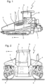
- the Figures 1 and 2 show construction machinery 1, specifically a road paver ( Figure 1 ) and a tandem roller ( Figure 2 ).
- the construction machines 1 preferably have a machine frame 3 with a control station 2 and a chassis.
- the construction machine 1 is operated from the control station 2.
- the chassis preferably comprises driving devices 6, which in the case of the road paver consist of Figure 1 For example, tracks or wheels can be used.
- the driving devices 6 are designed, for example, as compaction drums.
- the driving devices 6 could also be designed as wheels.
- the construction machines 1 preferably comprise a drive motor 4, which can be, for example, an internal combustion engine, in particular a diesel engine, or an electric motor, and which provides drive energy for operating the construction machine 1.
- a drive motor 4 can be, for example, an internal combustion engine, in particular a diesel engine, or an electric motor, and which provides drive energy for operating the construction machine 1.
- the construction machines 1 move in or against the working direction or forward direction a over the ground and work it, for example by laying a base course using the road paver or by compacting the soil using the tandem roller.
- the road paver according to Figure 1 preferably has a material hopper 5 in which paving material is stored during operation. This is then transported by the road paver to its rear, where it is preferably distributed by a transverse distribution device such as a screw conveyor and is smoothed and pre-compacted by a paving screed 7.
- a transverse distribution device such as a screw conveyor
- tandem rollers such as the one according to Figure 2 in use, which compact the soil to a desired compaction level through their own weight and optionally through an unbalance exciter device arranged in one or more of the compaction drums 6, oscillating movement of the compaction drums.
- the construction machines 1 have at least one control unit 29 in their control station 2, which is shown in detail in the Figures 3 and 4 Components of the operating unit 29 are a driver's seat 8 and an operating console 9 as well as, according to the invention, a transverse guide 31.
- the driver is preferably located on the driver's seat 8.
- the driver's seat 8 has a seat index point SIP ( Figure 4 ), which is a standard defined in the EN ISO 5353 standard.
- the standard also specifies a method for clearly determining the exact position of the seat index point SIP on any given seat.
- the seat index point SIP is located approximately in the middle of the seat, a few centimeters above the seat surface. More precise information can be found in the EN ISO 5353 standard.
- the control console 9 preferably has control elements for controlling the construction machine 1 by the driver sitting on the driver's seat 8.
- control elements for example, a steering device 10, which can be designed as a steering wheel.
- the driver's seat 8 is preferably arranged or fastened to a seat support 16 via a seat bearing 15.
- the seat bearing 15 can preferably comprise a height adjustment device for the driver's seat 8, so that the seat height can be adjusted vertically.
- the seat bearing 15 can also comprise a pivot bearing for the driver's seat 8, so that the driver's seat 8 is designed to be rotatable about a vertical axis of rotation.
- the seat support 16 is preferably connected to a console support 17, wherein the console support 17 preferably extends in the vertical direction and supports the control console 9. Together, the seat support 16 and the console support 17 preferably form a support structure 30, which overall represents a rigid connection between the control console 9 and the driver's seat 8.
- the support structure 30, is preferably attached to a support carriage 37 ( Figure 4 ), which preferably comprises a carriage frame 36, a sliding bushing 19, and a steering sliding bushing 25.
- the support carriage 37 is preferably movably mounted on a bearing rail 38, for example via a sliding roller, or is additionally supported thereon.
- the carriage frame 36 extends vertically and establishes a rigid connection between the sliding bushing 19 and the steering sliding bushing 25 and the bearing on the bearing rail 38.
- the support structure 30 is preferably mounted on a transverse guide 31 via the support carriage 37.
- the transverse guide 31 preferably comprises a transverse guide support 21 and at least one guide rail 18.
- the transverse guide support 21 preferably forms a support frame which supports the guide rail 18 in the operator's platform 2 of the construction machine 1.
- the guide rail 18 is in the In the exemplary embodiment shown, it is preferably designed as a round beam which is encompassed by the sliding bushing 19 of the support carriage 37.
- the sliding bushing 19 is mounted on the guide rail 18 via rolling bearings, in particular ball bearings, in such a way that the sliding bushing 19 and thus also the support carriage 37 are designed to be movable along the guide rail 18 or the transverse guide 31.
- the guide rail 18 is preferably aligned transversely or perpendicularly to the working direction a, so that the direction of movement of the support carriage 37 along the transverse guide 31 also preferably runs transversely to the working direction a.
- the transverse guide 31 can preferably also have a further bearing rail 38, which is preferably arranged at a vertical distance from the guide rail 18.
- the bearing rail 38 is also preferably connected to the support carriage 37 via a movable bearing, for example a roller bearing, in particular a sliding roller.
- the bearing on the bearing rail 38 preferably forms the counterbearing for the bearing on the guide rail 18, so that these two bearings are designed to absorb the weight, in particular the entire weight, of the support carriage 37.
- a steering output shaft 14 is preferably provided, which is part of the steering of the machine via the control console 9.
- a steering sliding bushing 25 is preferably also guided along the steering output shaft 14, which is preferably mounted on the steering output shaft 14 via rolling bearings, for example ball bearings.
- the steering output shaft 14 is preferably force-free with regard to supporting forces of the support carriage 37 and the components arranged thereon and thus does not fulfill a supporting function. Overall, it is therefore preferred if the support carriage 37 has two, in particular exclusively two, bearings for transmitting its weight to the transverse guide 31, wherein the two bearings preferably each allow movement of the support carriage 37 along the transverse guide.
- the two bearings are preferably spaced apart from one another in the vertical direction in order to prevent rotation of the support carriage 37 about the guide rail 18 and/or the bearing rail 38. It is preferred that, apart from these two bearings, no further connections exist between the support structure 30, the driver's seat 8, the control console 9, the support carriage 37 on the one hand and the transverse guide 31 or the operator's station 2 or the rest of the construction machine 1 on the other hand for the load-bearing mounting of the support carriage 37. There may also be a connection to the steering output shaft 14 for transmitting steering movements. However, this connection is also preferably not intended to absorb weight forces of the support carriage 37 on the transverse guide 31. In particular, the support structure 30 is designed to be free or floating on the side remote from the transverse guide 31.
- the support carriage 37, the support structure 30 and with it also the control console 9 and the driver's seat 8 can therefore preferably be adjusted or moved over the entire extent of the guide rail 18 and/or the bearing rail 38 along the transverse guide 31 transversely to the working direction a.
- a respective end position is preferably structurally predetermined for the transverse guide 31.
- the end position preferably describes a position of maximum displacement of the support carriage 37 along the transverse guide 31 in one of the two possible directions of displacement.
- the transverse guide 31 therefore preferably predetermines exactly two end positions, one for each of the directions of displacement along the transverse guide 31.
- the end positions are those positions in which the sliding bushing 19 and/or the steering sliding bushing 25 strikes the transverse guide support 21 and thereby limits the movement.
- another stop can be provided on the support carriage 37 and on the cross member 31, which stops or limits the movement of the support carriage 37 along the cross member 31 in the end positions.
- a locking device 24 may be provided to fix the support carriage 37 at any position between the two end positions on the cross member 31.
- the locking device 24 may comprise a rack, which may be arranged parallel to the guide rail 18 and/or the bearing rail 38.
- a locking operating element 20 ( Figure 3 ), for example in the form of a locking lever, which can be brought into or out of engagement with the locking device 24 by an operator.
- the locking control element 20 is preloaded into the movement-blocking position, i.e., into engagement with the locking device 24, for example by a spring.
- a drag chain 22 is preferably provided, via which the control elements of the control console 9 are connected to a control device of the construction machine 1.
- the drag chain 22 preferably serves to guide cables and other lines from the fixed transverse guide 31 to the movable support carriage 37 and to the control console 9 and its control elements.
- the drag chain is dimensioned in particular such that it is sufficient for adjusting the support carriage 37 between the two end positions of the transverse guide 31.
- the support structure 30, together with the driver's seat 8 and the control console 9, are designed to be pivotable about a pivot axis S.
- the support structure 30 is preferably arranged or mounted on the support carriage 37 so as to be pivotable about a pivot joint defining the pivot axis S.
- the pivot axis S runs in the vertical direction.
- the driver can therefore control the construction machine 1 via the control console 9 and, for example, the steering device 10 in the same intuitive way from the driver's seat 8, regardless of the respective pivot position of the support structure 30 about the pivot axis S. He therefore does not have to get used to or take into account a changed position of the control elements or the control console 9 when pivoting about the pivot axis S.
- the pivot axis S is preferably arranged in front of the driver's seat 8 in the working direction a, in particular just like the transverse guide 31. In other words, the pivot axis S is preferably arranged at the end of the support structure 30 opposite the driver's seat 8.
- the pivot path of the driver's seat 8 is as large as possible, which in turn leads to the position and orientation of the driver's seat 8 with respect to the construction machine 1 or the operator's station 2 changing particularly significantly.
- the driver can freely select the swivel position of the driver's seat 8 about the swivel axis S, he can choose from a variety of different positions and orientations of the driver's seat 8, depending on the requirements of his current work situation regarding the overview of the construction machine 1 or its external environment.
- a locking device 32 ( Figure 4 ) is provided.
- the locking device 32 is preferably arranged on the pivot joint of the pivot axis S and comprises, for example, a gear ring and a locking control element 23 such as a locking lever.
- the locking control element 23 has a stop with which it can positively engage in the gear ring of the locking device 32 in order to prevent rotation of the support structure 30 relative to the support carriage 37 or the transverse guide 31. It is preferred that the locking control element 23 is preloaded into the locking position by a spring preload.
- a steering device 10 in the form of a steering wheel is arranged on the control console 9.
- the steering wheel can be part of a mechanical-hydraulic steering system.
- the rotational movement of the steering wheel which is initiated by a driver, is preferably transmitted to the steering output shaft 14. Details on this can be found in the aforementioned DE 10 2010 035 270 B4 Alternatively, a cable connection can be provided via which signals from an electric steering device can be transmitted.
- FIGs 5-9 show different positions or orientations that the driver's seat 8 and the control console 9 together with the support structure 30 can assume by a movement along the transverse guide 31 and by a pivoting about the pivot axis S.
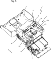
- Figure 5 shows an example of a road paver from a perspective view diagonally from the rear and top.
- the operator's cab 2 of the road paver is shown without a roof for reasons of clarity.
- the present invention relates to both operator's cabs 2 with and without a roof.
- the driver's seat 8 is arranged in the middle of the driver's station 2 and is in a straight-ahead position.
- a joystick 34 is arranged on the armrest console 33, which can be provided in addition to or as an alternative to the steering device 10 designed as a steering wheel.
- the construction machine 1 can have an electronic control system or an electronic steering system which is controlled by the joystick 34. It is also possible for two such additional control consoles to be provided, for example on both armrests.
- the driver's seat 8 is in the left end position, specified by the transverse guide 31, with respect to the movement transverse to the working direction a.
- the driver's seat 8 and the control console 9 are located in this position directly next to the left operator's cab door 26.
- the driver's seat 8 and the control console 9 could also be moved along the transverse guide 31 to the right side of the operator's cab 2 into the right end position, so that they are located directly next to the right operator's cab door 26.
- Figure 6 the left end position is shown.
- Figure 6 the vehicle pillars of the operator's station 2 of the construction machine 1, specifically the A-pillar A and the B-pillar B.
- vehicle pillar A in the example shown is directly in the driver's field of vision and hinders his observation of the work environment.
- FIG. 7 A situation is shown in which the left operator's cab door 26 is open.
- the support structure 30, together with the control console 9 and the driver's seat 8 is pivoted outwards about the pivot axis S.
- the pivoting movement outwards refers to a pivoting movement about the pivot axis S away from the central longitudinal axis M of the construction machine 1.
- the driver's seat 8 is swung out through the open operator's cab door 26 or the opening cleared by the open operator's cab door 26 into an area which, when the operator's cab door 26 is closed, is Figure 6 was still outside the operator's station 2.
- the driver's seat 8 has been moved by pivoting about the pivot axis S into a position that is further away from the central longitudinal axis M of the construction machine 1 than the A-pillar A.
- this information relates in particular to the seat index point SIP of the driver's seat 8.
- the driver can comfortably look past the A-pillar A from the driver's seat 8 and observe the external surroundings of the construction machine 1.
- it is particularly easy for him to look past another vehicle on the construction site, for example a truck driving in front of or behind the construction machine 1.
- the usual communication with the driver of this other vehicle on the construction site is also facilitated.
- he can also look along the outer contour of the machine and, for example, determine with high precision where the construction machine 1 is traveling and which parts of the ground are therefore being worked by it and which are not. Distances to obstacles can also be determined particularly precisely in this way.
- the driver can open the cab door 26 manually.
- a coupling device 35 ( Figure 3 ) may be provided, which leads to an automatic opening of the operator's cab door 26 when the support structure 30 is pivoted about the pivot axis S in one of the end positions of the transverse guide 31 onto the operator's cab door 26.
- the coupling device 35 can, for example, be a stop that pushes the operator's cab door 26 open outwards.
- the coupling device 35 can also comprise a magnet, so that the operator's cab door 26 can also be automatically closed by the coupling device 35 when the support structure 30 and the driver's seat 8 as well as the control console 9 are pivoted from the pivoted-out position back into the straight-ahead position.
- a pivoting floor 27 is preferably provided. This preferably has the shape of a circular sector and is pivotable about a pivot axis, in particular between a storage position and a working position.
- the pivot axis of the pivoting floor 27 is preferably coaxial with a door rotation axis T ( Figure 8 ), wherein the pivot axis of the pivoting floor 27 is also preferably arranged at the tip of the circular sector.
- the pivoting floor 27 is preferably arranged in a storage compartment under the operator's cab floor 28 and can be pulled out from there into a working position, in which the pivoting floor 27 preferably bridges or closes the area between the operator's cab floor 28 and the open operator's cab door 26 in the horizontal plane.
- the pivoting floor 27 thus extends the operator's cab floor 28 when the operator's cab door 26 is open, extends beyond the actual extent of the operator's cab floor 28 and therefore secures the driver, who is no longer above the operator's cab floor 28 when the operator's seat 8 is in the swiveled-out position.
- the operator's seat 8 is then arranged above the swivel floor 27 in the working position.
- Figure 8 shows that the displacement direction h of the support structure 30 with the control console 9 and the driver's seat 8 runs transversely to the working direction a.
- pivoting of the support structure 30 or the control console 9 and the driver's seat 8 about the pivot axis S is preferably characterized by a pivot angle W, which is spanned by two vertical planes, each of which runs through the seat index point SIP of the driver's seat 8 and the pivot axis S.
- One vertical plane results from the straight-ahead position of the driver's seat 8 before pivoting about the pivot axis S and the second vertical plane results from the lateral position of the driver's seat 8 after pivoting about the pivot axis S.
- the pivot angle W measured in the horizontal plane results. The larger the pivot angle W, the further the driver's seat 8 and its seat index point SIP can be pivoted outwards.
- Figure 8 It is also apparent that the operator's cab door 26 can be opened or closed about a door rotation axis T.
- the door rotation axis T is preferably arranged in the working direction a in front of the pivot axis S.
- the door rotation axis T is arranged by an offset v in the working direction a in front of the pivot axis S. In this way, it is ensured that pivoting of the support structure 30 and in particular of the control console 9 about the pivot axis S is possible even in the end positions predetermined by the transverse guide 31.
- the control console 9 would be positioned with its left rear corner, which is in Figure 8 protrudes beyond the outer contour of the construction machine 1, collide with the operator's cab door 26. Due to the correspondingly preferred arrangement of the door rotation axis T in the working direction a in front of the pivot axis S, sufficient space is provided in this area so that the operating console 9 can also pivot freely into the lateral position.
- Figure 8 It also shows that the seat index point SIP of the driver's seat 8 can preferably be pivoted outwards beyond an outer contour K of the construction machine 1.
- the outer contour K of the construction machine 1 is defined by the outer surface of the construction machine 1 and in particular of the operator's station 2 when the operator's station door 26 is closed. the area in which the closed operator's cab door 26 is arranged, the outer contour K of the construction machine 1 is therefore defined by the position of the outer surface of the closed operator's cab door 26.
- the outer contour K of the construction machine 1 remains as a virtual reference surface in the same position in which it is located when the operator's cab door 26 is closed, even when the operator's cab door 26 is open.
- the driver's seat 8 and in particular also the seat index point SIP of the driver's seat 8 are pivoted outwards beyond this outer contour K by pivoting the support structure 30 about the pivot axis S.
- the seat index point SIP is in particular moved beyond the outer contour K in such a way that it has a distance d to the outer contour K.
- the distance d is measured in particular in the direction transverse to the working direction a.
- Figure 9 shows that pivoting of the support structure 30 with the driver's seat 8 and the control console 9 around the pivot axis S is also possible in a position along the transverse guide 31 which is not an end position.
- the driver's seat 8 is located entirely within the operator's station 2, even though it is in a lateral position, i.e., pivoted about the pivot axis S.
- This also allows the driver to adopt different positions and different orientations of the driver's seat within the operator's station, thus improving his overview of the construction machine 1 and the work process.
- the invention therefore makes it possible to significantly improve the flexibility of an operating unit 29 of a generic construction machine 1 and thus increase work safety and work quality.
Landscapes
- Engineering & Computer Science (AREA)
- Architecture (AREA)
- Civil Engineering (AREA)
- Structural Engineering (AREA)
- Component Parts Of Construction Machinery (AREA)
Claims (17)
- Machine de construction (1), en particulier finisseur ou rouleau tandem, pour le traitement d'un sol dans une direction de travail (a), avec- un châssis de machine (3),- un poste de conduite (2) et- au moins un dispositif de déplacement (6), et- une unité de commande (29),l'unité de commande (29) comprenant- un siège conducteur (8) pour un conducteur de la machine de construction (1),- une console de commande (9) avec des éléments de commande pour la commande de la machine de construction (1) par le conducteur,- une structure porteuse (30), sur laquelle sont disposés à la fois le siège conducteur (8) et la console de commande (9), et- un guidage transversal (31) avec au moins un rail de guidage (18),dans laquelle la structure porteuse (30) est montée de manière mobile sur l'au moins un rail de guidage (18), de sorte que la structure porteuse (30) est conçue pour être mobile, avec le siège conducteur (8) et la console de commande (9), le long d'au moins un rail de guidage (18),caractérisée en ce quela structure porteuse (30), avec le siège conducteur (8) et la console de commande (9), est conçue pour pivoter autour d'un axe de pivotement (S) s'étendant dans la direction verticale, l'axe de pivotement (S) étant disposé dans la direction de travail (a) devant le siège conducteur (8).
- Machine de construction (1) selon la revendication 1,
caractérisée en ce que
l'axe de pivotement (S) et la console de commande (9) sont disposés dans la direction de travail (a) devant le siège conducteur (8) sur la structure porteuse (30). - Machine de construction (1) selon l'une des revendications précédentes,
caractérisée en ce que
la structure porteuse (30) avec le siège conducteur (8) et la console de commande (9) est conçue pour pivoter exclusivement autour de l'axe de pivotement (S). - Machine de construction (1) selon l'une des revendications précédentes,
caractérisée en ce que
le guidage transversal (31) comprend, en plus du rail de guidage (18), un autre rail de support (38) disposé verticalement à distance du rail de guidage (18), qui s'étend de préférence parallèlement au rail de guidage (18), et en ce que la structure porteuse (30) est montée de manière mobile sur le rail de guidage (18) et le rail de support (38). - Machine de construction (1) selon l'une des revendications précédentes,
caractérisée en ce que
un chariot de support (37) est prévu, sur lequel la structure porteuse (30) avec le siège conducteur (8) et la console de commande (9) est montée de manière pivotante autour de l'axe de pivotement (S), et en ce que le chariot de support (37) est monté de manière mobile sur le guidage transversal (31), de sorte que le chariot de support (37) est conçu pour être mobile avec la structure porteuse (30), le siège conducteur (8) et la console de commande (9) le long du guidage transversal (31), en particulier le long du rail de guidage (18). - Machine de construction (1) selon l'une des revendications précédentes,
caractérisée en ce que
la structure porteuse (30) est montée exclusivement sur le guidage transversal (31) et en ce que la structure porteuse (30) est montée exclusivement dans la direction de travail (a) devant le siège conducteur (8) sur le guidage transversal (31). - Machine de construction (1) selon la revendication précédente,
caractérisée en ce que
le siège conducteur (8) présente un point d'indice de siège (SIP), et en ce que la structure porteuse (30) est montée de manière pivotante autour de l'axe de pivotement (S) sur le rail de guidage (18) de telle sorte que le siège conducteur (8) peut pivoter entre une position en ligne droite et une position latérale, une verticale passant par le point d'indice de siège (SIP) et l'axe de pivotement (S) en position en ligne droite et une verticale passant par le point d'indice de siège (SIP) et l'axe de pivotement (S) en position latérale formant un angle de pivotement (W), et dans laquelle l'angle de pivotement (W) est en particulier au moins jusqu'à 40°, de préférence au moins jusqu'à 50° ou au moins jusqu'à 60° ou au moins jusqu'à 70° ou au moins jusqu'à 80° ou au moins jusqu'à 90°. - Machine de construction (1) selon la revendication précédente,
caractérisée en ce que
le plan vertical passant par le point d'indice de siège (SIP) et l'axe de pivotement (S) est aligné parallèlement à la direction de travail (a) lorsque le siège conducteur (8) est en position en ligne droite. - Machine de construction (1) selon l'une des revendications précédentes 7 à 8,
caractérisée en ce que
le guidage transversal (31) s'étend transversalement à la direction de travail (a) et définit à ses extrémités espacées transversalement à la direction de travail (a) une position finale respective pour le siège conducteur (8), le siège conducteur (8) étant disposé dans une de ces positions finales en position en ligne droite de telle sorte que le point d'indice de siège (SIP) est disposé en direction transversale à la direction de travail (a) au niveau du guidage transversal (31), et en ce que le siège conducteur (8) peut pivoter dans ces positions finales autour de l'axe de pivotement (S) en s'éloignant du rail de guidage (18) de telle sorte que le point d'indice de siège (SIP) se situe en direction transversale à la direction de travail (a) derrière le guidage transversal (31). - Machine de construction (1) selon la revendication précédente,
caractérisée en ce que
le point d'indice de siège (SIP) du siège conducteur (8) est réglable sur une distance (d) au-delà du contour extérieur de la machine de construction (1) transversalement à la direction de travail (a), la distance (d) étant d'au moins 5 cm, de préférence d'au moins 10 cm ou d'au moins 15 cm ou d'au moins 20 cm ou d'au moins 25 cm ou d'au moins 30 cm. - Machine de construction (1) selon l'une des revendications précédentes,
caractérisée en ce que
le poste de conduite (2) comprend au moins une porte de poste de conduite (26), la porte de poste de conduite (26) présentant une face extérieure avec laquelle elle forme un contour extérieur de la machine de construction (1) à l'état fermé, et en ce que le siège conducteur (8), en particulier le point d'indice de siège (SIP) du siège conducteur (8), lorsque la porte de poste de conduite (26) est ouverte, peut être réglé par pivotement du siège conducteur (8) autour de l'axe de pivotement (S) en s'éloignant d'un axe longitudinal central (M) de la machine de construction (1) jusqu'au-delà de ce contour extérieur de la machine de construction (1) transversalement à la direction de travail (a). - Machine de construction (1) selon la revendication 11,
caractérisée en ce que
un dispositif d'accouplement (35) est prévu, qui, lors d'un pivotement du siège conducteur (8) autour de l'axe de pivotement (S) à côté de la porte de poste de conduite (26), ouvre et/ou ferme automatiquement la porte de poste de conduite (26). - Machine de construction (1) selon l'une des revendications 11 ou 12,
caractérisée en ce que
la porte de poste de conduite (26) est conçue de telle sorte qu'elle peut être ouverte et fermée autour d'un axe de rotation de porte (T), l'axe de rotation de porte (T) étant situé plus en avant dans la direction de travail (a) que l'axe de pivotement (S). - Machine de construction (1) selon l'une des revendications précédentes,
caractérisée en ce que
un plancher pivotant (27) s'étendant horizontalement est présent, qui est réglable, en particulier pivotant, entre une position de rangement, dans laquelle le plancher pivotant (27) est rentré sous un plancher de poste de conduite (28), et une position de travail, dans laquelle le plancher pivotant (27) élargit le plancher de poste de conduite (28) transversalement à la direction de travail (a), en particulier jusqu'à la porte de poste de conduite (26) ouverte. - Machine de construction (1) selon la revendication précédente,
caractérisée en ce que
le mouvement du plancher pivotant (27) entre la position de rangement et la position de travail est couplé au mouvement de la porte de poste de conduite (26) et/ou de la structure porteuse (30), de sorte que le plancher pivotant (27) est automatiquement entraîné en mouvement avec la porte de poste de conduite (26) ou la structure porteuse (30). - Machine de construction (1) selon l'une des revendications précédentes,
caractérisée en ce que
un dispositif de verrouillage (24, 32) est prévu pour verrouiller la structure porteuse (30) avec le siège conducteur (8) et la console de commande (9) dans différentes positions le long du guidage transversal (31) et/ou dans différentes positions de pivotement autour de l'axe de pivotement (S). - Machine de construction (1) selon l'une des revendications précédentes,
caractérisée en ce que
elle présente au moins l'une des caractéristiques suivantes :- elle présente une console d'accoudoir supplémentaire (33) avec des éléments de commande pour le conducteur, en particulier sur le siège conducteur (8) ;- elle présente un système de direction électronique pour la machine de construction (1), comprenant en particulier un joystick (34) ;- le siège conducteur (8) est conçu pour être réglable en hauteur ;- le siège conducteur (8) est conçu pour être rotatif ;- la structure porteuse (30) comprend un support de siège (16) s'étendant dans la direction radiale de l'axe de pivotement (S) ;- la structure porteuse (30) comprend un support de console (17) s'étendant verticalement.
Applications Claiming Priority (1)
| Application Number | Priority Date | Filing Date | Title |
|---|---|---|---|
| DE102022210852.3A DE102022210852A1 (de) | 2022-10-14 | 2022-10-14 | BAUMASCHINE, INSBESONDERE STRAßENFERTIGER ODER TANDEMWALZE |
Publications (2)
| Publication Number | Publication Date |
|---|---|
| EP4353905A1 EP4353905A1 (fr) | 2024-04-17 |
| EP4353905B1 true EP4353905B1 (fr) | 2025-06-18 |
Family
ID=88315486
Family Applications (1)
| Application Number | Title | Priority Date | Filing Date |
|---|---|---|---|
| EP23202751.6A Active EP4353905B1 (fr) | 2022-10-14 | 2023-10-10 | Engin de chantier, notamment finisseur ou rouleau tandem |
Country Status (4)
| Country | Link |
|---|---|
| US (1) | US20240125058A1 (fr) |
| EP (1) | EP4353905B1 (fr) |
| CN (1) | CN117888424A (fr) |
| DE (1) | DE102022210852A1 (fr) |
Families Citing this family (3)
| Publication number | Priority date | Publication date | Assignee | Title |
|---|---|---|---|---|
| DE102021212546A1 (de) * | 2021-11-08 | 2023-05-11 | Bomag Gmbh | Tandemwalze zur Verdichtung eines Bodenuntergrundes |
| DE102024106046A1 (de) * | 2024-03-01 | 2025-09-04 | Bomag Gmbh | Straßenbaumaschine |
| CN120331089B (zh) * | 2025-04-30 | 2026-05-05 | 徐工集团工程机械股份有限公司道路机械分公司 | 一种具有可折叠侧边操作位的沥青混凝土转运车 |
Family Cites Families (12)
| Publication number | Priority date | Publication date | Assignee | Title |
|---|---|---|---|---|
| SE503655C2 (sv) * | 1994-11-09 | 1996-07-29 | Dynapac Heavy Equipment Ab | Förarhytt till vägvält som medger full siktkontroll för föraren |
| DE19813474A1 (de) * | 1998-03-26 | 1999-10-07 | Vibromax Bodenverdichtungsmasc | Bodenverdichtungsmaschine mit verschieblicher Fahrstandslafette |
| EP1961607B1 (fr) | 2007-02-26 | 2010-01-13 | Bomag Gmbh | Siège destiné à être installé dans une cabine de conduite |
| DE102010035270B4 (de) | 2010-08-24 | 2013-08-22 | Bomag Gmbh | Lenkvorrichtung für eine selbstfahrende Bau- oder Nutzmaschine sowie Bau- oder Nutzmaschine mit einer derartigen Lenkvorrichtung |
| DE202012003697U1 (de) * | 2012-04-12 | 2013-07-15 | Joseph Vögele AG | Straßenfertiger sowie Sitzkonsole |
| DE102015012560A1 (de) * | 2014-10-07 | 2016-04-07 | Bomag Gmbh | Fahrstand für eine Baumaschine und Baumaschine mit einem Fahrstand |
| DE102015012666A1 (de) * | 2015-09-30 | 2017-03-30 | Bomag Gmbh | Baumaschine, insbesondere Gummiradwalze oder Straßenfertiger |
| DE102016104568A1 (de) * | 2016-03-14 | 2017-09-14 | Teamobility Gmbh | Fahrzeug mit einer Mittelsitzposition |
| DE102017002225A1 (de) | 2016-03-18 | 2017-09-21 | Bomag Gmbh | Straßenfertiger mit Steuereinheit zur Bestimmung des Gewichts und/oder der Schwerpunktlage und/oder der Breite der Bohle und Verfahren |
| WO2017214963A1 (fr) * | 2016-06-17 | 2017-12-21 | Volvo Construction Equipment Ab | Siège rotatif et mobile |
| DE102018007825A1 (de) | 2018-10-04 | 2020-04-09 | Bomag Gmbh | Verfahren zur Steuerung einer Bodenverdichtungsmaschine und Bodenverdichtungsmaschine |
| PL4029727T3 (pl) * | 2021-01-13 | 2024-10-28 | Joseph Vögele AG | Maszyna budowlana z konsolą siedziska |
-
2022
- 2022-10-14 DE DE102022210852.3A patent/DE102022210852A1/de active Pending
-
2023
- 2023-10-10 EP EP23202751.6A patent/EP4353905B1/fr active Active
- 2023-10-13 CN CN202311331895.2A patent/CN117888424A/zh active Pending
- 2023-10-13 US US18/486,406 patent/US20240125058A1/en active Pending
Also Published As
| Publication number | Publication date |
|---|---|
| CN117888424A (zh) | 2024-04-16 |
| EP4353905A1 (fr) | 2024-04-17 |
| DE102022210852A1 (de) | 2024-05-08 |
| US20240125058A1 (en) | 2024-04-18 |
Similar Documents
| Publication | Publication Date | Title |
|---|---|---|
| EP4353905A1 (fr) | Engin de chantier, notamment finisseur ou rouleau tandem | |
| EP0054948B1 (fr) | Poste de conducteur | |
| EP3078773B2 (fr) | Engin de construction automobile | |
| EP3489416B1 (fr) | Machine de traitement du sol avec un dispositif deployable et retractable associant pare-brise et toit protecteur et procédé pour modifier la hauteur de cette machine de traitement du sol | |
| DE102015012560A1 (de) | Fahrstand für eine Baumaschine und Baumaschine mit einem Fahrstand | |
| EP2746103B1 (fr) | Siège de véhicule utilitaire doté d'une partie de coulisseau transversal à double blocage | |
| EP2369066A2 (fr) | Poste de travail d'utilisateur d'un engin | |
| EP2650437B1 (fr) | Finisseur de route avec pupitre de commande mobile | |
| DE102017009248B4 (de) | Kleinfertiger | |
| EP4029727B1 (fr) | Machine de construction avec console d'assise | |
| DE102018000576A1 (de) | Straßenfertiger mit Sichtausnehmung im Materialbunker | |
| DE102019125553A1 (de) | Bewegliche bedienerstation für verbesserte sicht | |
| EP2593333A1 (fr) | Véhicule à structure modulaire | |
| DE102016118479B4 (de) | Landwirtschaftliche Arbeitsmaschine | |
| EP4450708B1 (fr) | Engin de construction routière, en particulier finisseur ou rouleau tandem | |
| DE102014001488A1 (de) | Straßenbaumaschine, insbesondere Straßenfertiger oder Beschicker | |
| WO2019120606A1 (fr) | Machine automotrice de fraisage du sol | |
| DE4409514C2 (de) | Verstellbares Gegengewicht für eine Baumaschine und Hydraulikbagger, der mit einem verstellbaren Gegengewicht ausgerüstet ist | |
| DE19823221B4 (de) | Flurförderzeug, insbesondere Frontsitzgabelstapler | |
| EP1337712B1 (fr) | Machine de compactage du sol | |
| DE202011105309U1 (de) | Kabinenlose selbstfahrende Baumaschine, insbesondere Straßenfräse | |
| EP4151463B1 (fr) | Poste de travail opérateur pour une machine de construction et machine de construction | |
| EP1961607B1 (fr) | Siège destiné à être installé dans une cabine de conduite | |
| DE102012004149B4 (de) | Längseinstellbarer Fahrzeugsitz | |
| EP4368481B1 (fr) | Fraiseuse routière, procédé de conduite d'une fraiseuse routière et procédé de positionnement |
Legal Events
| Date | Code | Title | Description |
|---|---|---|---|
| PUAI | Public reference made under article 153(3) epc to a published international application that has entered the european phase |
Free format text: ORIGINAL CODE: 0009012 |
|
| STAA | Information on the status of an ep patent application or granted ep patent |
Free format text: STATUS: THE APPLICATION HAS BEEN PUBLISHED |
|
| AK | Designated contracting states |
Kind code of ref document: A1 Designated state(s): AL AT BE BG CH CY CZ DE DK EE ES FI FR GB GR HR HU IE IS IT LI LT LU LV MC ME MK MT NL NO PL PT RO RS SE SI SK SM TR |
|
| STAA | Information on the status of an ep patent application or granted ep patent |
Free format text: STATUS: REQUEST FOR EXAMINATION WAS MADE |
|
| 17P | Request for examination filed |
Effective date: 20241010 |
|
| RBV | Designated contracting states (corrected) |
Designated state(s): AL AT BE BG CH CY CZ DE DK EE ES FI FR GB GR HR HU IE IS IT LI LT LU LV MC ME MK MT NL NO PL PT RO RS SE SI SK SM TR |
|
| GRAP | Despatch of communication of intention to grant a patent |
Free format text: ORIGINAL CODE: EPIDOSNIGR1 |
|
| STAA | Information on the status of an ep patent application or granted ep patent |
Free format text: STATUS: GRANT OF PATENT IS INTENDED |
|
| RIC1 | Information provided on ipc code assigned before grant |
Ipc: E01C 19/48 20060101ALI20250313BHEP Ipc: E01C 19/23 20060101AFI20250313BHEP |
|
| INTG | Intention to grant announced |
Effective date: 20250325 |
|
| GRAS | Grant fee paid |
Free format text: ORIGINAL CODE: EPIDOSNIGR3 |
|
| GRAA | (expected) grant |
Free format text: ORIGINAL CODE: 0009210 |
|
| STAA | Information on the status of an ep patent application or granted ep patent |
Free format text: STATUS: THE PATENT HAS BEEN GRANTED |
|
| AK | Designated contracting states |
Kind code of ref document: B1 Designated state(s): AL AT BE BG CH CY CZ DE DK EE ES FI FR GB GR HR HU IE IS IT LI LT LU LV MC ME MK MT NL NO PL PT RO RS SE SI SK SM TR |
|
| REG | Reference to a national code |
Ref country code: GB Ref legal event code: FG4D Free format text: NOT ENGLISH |
|
| REG | Reference to a national code |
Ref country code: CH Ref legal event code: EP |
|
| P01 | Opt-out of the competence of the unified patent court (upc) registered |
Free format text: CASE NUMBER: APP_25183/2025 Effective date: 20250527 |
|
| REG | Reference to a national code |
Ref country code: DE Ref legal event code: R096 Ref document number: 502023001185 Country of ref document: DE |
|
| REG | Reference to a national code |
Ref country code: CH Ref legal event code: EP |
|
| REG | Reference to a national code |
Ref country code: IE Ref legal event code: FG4D Free format text: LANGUAGE OF EP DOCUMENT: GERMAN |
|
| PG25 | Lapsed in a contracting state [announced via postgrant information from national office to epo] |
Ref country code: FI Free format text: LAPSE BECAUSE OF FAILURE TO SUBMIT A TRANSLATION OF THE DESCRIPTION OR TO PAY THE FEE WITHIN THE PRESCRIBED TIME-LIMIT Effective date: 20250618 |
|
| REG | Reference to a national code |
Ref country code: LT Ref legal event code: MG9D |
|
| PG25 | Lapsed in a contracting state [announced via postgrant information from national office to epo] |
Ref country code: NO Free format text: LAPSE BECAUSE OF FAILURE TO SUBMIT A TRANSLATION OF THE DESCRIPTION OR TO PAY THE FEE WITHIN THE PRESCRIBED TIME-LIMIT Effective date: 20250918 Ref country code: GR Free format text: LAPSE BECAUSE OF FAILURE TO SUBMIT A TRANSLATION OF THE DESCRIPTION OR TO PAY THE FEE WITHIN THE PRESCRIBED TIME-LIMIT Effective date: 20250919 |
|
| PG25 | Lapsed in a contracting state [announced via postgrant information from national office to epo] |
Ref country code: BG Free format text: LAPSE BECAUSE OF FAILURE TO SUBMIT A TRANSLATION OF THE DESCRIPTION OR TO PAY THE FEE WITHIN THE PRESCRIBED TIME-LIMIT Effective date: 20250618 |
|
| PG25 | Lapsed in a contracting state [announced via postgrant information from national office to epo] |
Ref country code: HR Free format text: LAPSE BECAUSE OF FAILURE TO SUBMIT A TRANSLATION OF THE DESCRIPTION OR TO PAY THE FEE WITHIN THE PRESCRIBED TIME-LIMIT Effective date: 20250618 |
|
| PG25 | Lapsed in a contracting state [announced via postgrant information from national office to epo] |
Ref country code: RS Free format text: LAPSE BECAUSE OF FAILURE TO SUBMIT A TRANSLATION OF THE DESCRIPTION OR TO PAY THE FEE WITHIN THE PRESCRIBED TIME-LIMIT Effective date: 20250918 |
|
| REG | Reference to a national code |
Ref country code: NL Ref legal event code: MP Effective date: 20250618 |
|
| PG25 | Lapsed in a contracting state [announced via postgrant information from national office to epo] |
Ref country code: LV Free format text: LAPSE BECAUSE OF FAILURE TO SUBMIT A TRANSLATION OF THE DESCRIPTION OR TO PAY THE FEE WITHIN THE PRESCRIBED TIME-LIMIT Effective date: 20250618 |
|
| PG25 | Lapsed in a contracting state [announced via postgrant information from national office to epo] |
Ref country code: NL Free format text: LAPSE BECAUSE OF FAILURE TO SUBMIT A TRANSLATION OF THE DESCRIPTION OR TO PAY THE FEE WITHIN THE PRESCRIBED TIME-LIMIT Effective date: 20250618 |
|
| PG25 | Lapsed in a contracting state [announced via postgrant information from national office to epo] |
Ref country code: PT Free format text: LAPSE BECAUSE OF FAILURE TO SUBMIT A TRANSLATION OF THE DESCRIPTION OR TO PAY THE FEE WITHIN THE PRESCRIBED TIME-LIMIT Effective date: 20251020 |
|
| PG25 | Lapsed in a contracting state [announced via postgrant information from national office to epo] |
Ref country code: IS Free format text: LAPSE BECAUSE OF FAILURE TO SUBMIT A TRANSLATION OF THE DESCRIPTION OR TO PAY THE FEE WITHIN THE PRESCRIBED TIME-LIMIT Effective date: 20251018 |
|
| PGFP | Annual fee paid to national office [announced via postgrant information from national office to epo] |
Ref country code: DE Payment date: 20251020 Year of fee payment: 3 |
|
| PG25 | Lapsed in a contracting state [announced via postgrant information from national office to epo] |
Ref country code: SM Free format text: LAPSE BECAUSE OF FAILURE TO SUBMIT A TRANSLATION OF THE DESCRIPTION OR TO PAY THE FEE WITHIN THE PRESCRIBED TIME-LIMIT Effective date: 20250618 |
|
| PGFP | Annual fee paid to national office [announced via postgrant information from national office to epo] |
Ref country code: AT Payment date: 20260113 Year of fee payment: 3 |
|
| PGFP | Annual fee paid to national office [announced via postgrant information from national office to epo] |
Ref country code: IT Payment date: 20251031 Year of fee payment: 3 |
|
| PG25 | Lapsed in a contracting state [announced via postgrant information from national office to epo] |
Ref country code: CZ Free format text: LAPSE BECAUSE OF FAILURE TO SUBMIT A TRANSLATION OF THE DESCRIPTION OR TO PAY THE FEE WITHIN THE PRESCRIBED TIME-LIMIT Effective date: 20250618 |
|
| PG25 | Lapsed in a contracting state [announced via postgrant information from national office to epo] |
Ref country code: PL Free format text: LAPSE BECAUSE OF FAILURE TO SUBMIT A TRANSLATION OF THE DESCRIPTION OR TO PAY THE FEE WITHIN THE PRESCRIBED TIME-LIMIT Effective date: 20250618 |
|
| PG25 | Lapsed in a contracting state [announced via postgrant information from national office to epo] |
Ref country code: EE Free format text: LAPSE BECAUSE OF FAILURE TO SUBMIT A TRANSLATION OF THE DESCRIPTION OR TO PAY THE FEE WITHIN THE PRESCRIBED TIME-LIMIT Effective date: 20250618 |
|
| PG25 | Lapsed in a contracting state [announced via postgrant information from national office to epo] |
Ref country code: SK Free format text: LAPSE BECAUSE OF FAILURE TO SUBMIT A TRANSLATION OF THE DESCRIPTION OR TO PAY THE FEE WITHIN THE PRESCRIBED TIME-LIMIT Effective date: 20250618 |
|
| PG25 | Lapsed in a contracting state [announced via postgrant information from national office to epo] |
Ref country code: ES Free format text: LAPSE BECAUSE OF FAILURE TO SUBMIT A TRANSLATION OF THE DESCRIPTION OR TO PAY THE FEE WITHIN THE PRESCRIBED TIME-LIMIT Effective date: 20250618 |
|
| PG25 | Lapsed in a contracting state [announced via postgrant information from national office to epo] |
Ref country code: RO Free format text: LAPSE BECAUSE OF FAILURE TO SUBMIT A TRANSLATION OF THE DESCRIPTION OR TO PAY THE FEE WITHIN THE PRESCRIBED TIME-LIMIT Effective date: 20250618 |
|
| REG | Reference to a national code |
Ref country code: DE Ref legal event code: R097 Ref document number: 502023001185 Country of ref document: DE |
|
| PG25 | Lapsed in a contracting state [announced via postgrant information from national office to epo] |
Ref country code: DK Free format text: LAPSE BECAUSE OF FAILURE TO SUBMIT A TRANSLATION OF THE DESCRIPTION OR TO PAY THE FEE WITHIN THE PRESCRIBED TIME-LIMIT Effective date: 20250618 |
|
| PLBE | No opposition filed within time limit |
Free format text: ORIGINAL CODE: 0009261 |
|
| STAA | Information on the status of an ep patent application or granted ep patent |
Free format text: STATUS: NO OPPOSITION FILED WITHIN TIME LIMIT |
|
| REG | Reference to a national code |
Ref country code: CH Ref legal event code: L10 Free format text: ST27 STATUS EVENT CODE: U-0-0-L10-L00 (AS PROVIDED BY THE NATIONAL OFFICE) Effective date: 20260430 |