EP4354012A1 - Druckbehälterauskleidung und verfahren zur herstellung einer druckbehälterauskleidung - Google Patents
Druckbehälterauskleidung und verfahren zur herstellung einer druckbehälterauskleidung Download PDFInfo
- Publication number
- EP4354012A1 EP4354012A1 EP22820088.7A EP22820088A EP4354012A1 EP 4354012 A1 EP4354012 A1 EP 4354012A1 EP 22820088 A EP22820088 A EP 22820088A EP 4354012 A1 EP4354012 A1 EP 4354012A1
- Authority
- EP
- European Patent Office
- Prior art keywords
- liner
- pressure vessel
- liner member
- axial direction
- cylindrical shape
- Prior art date
- Legal status (The legal status is an assumption and is not a legal conclusion. Google has not performed a legal analysis and makes no representation as to the accuracy of the status listed.)
- Granted
Links
Images


Classifications
-
- F—MECHANICAL ENGINEERING; LIGHTING; HEATING; WEAPONS; BLASTING
- F17—STORING OR DISTRIBUTING GASES OR LIQUIDS
- F17C—VESSELS FOR CONTAINING OR STORING COMPRESSED, LIQUEFIED OR SOLIDIFIED GASES; FIXED-CAPACITY GAS-HOLDERS; FILLING VESSELS WITH, OR DISCHARGING FROM VESSELS, COMPRESSED, LIQUEFIED, OR SOLIDIFIED GASES
- F17C1/00—Pressure vessels, e.g. gas cylinder, gas tank, replaceable cartridge
- F17C1/16—Pressure vessels, e.g. gas cylinder, gas tank, replaceable cartridge constructed of plastics materials
-
- F—MECHANICAL ENGINEERING; LIGHTING; HEATING; WEAPONS; BLASTING
- F16—ENGINEERING ELEMENTS AND UNITS; GENERAL MEASURES FOR PRODUCING AND MAINTAINING EFFECTIVE FUNCTIONING OF MACHINES OR INSTALLATIONS; THERMAL INSULATION IN GENERAL
- F16J—PISTONS; CYLINDERS; SEALINGS
- F16J12/00—Pressure vessels in general
-
- B—PERFORMING OPERATIONS; TRANSPORTING
- B29—WORKING OF PLASTICS; WORKING OF SUBSTANCES IN A PLASTIC STATE IN GENERAL
- B29C—SHAPING OR JOINING OF PLASTICS; SHAPING OF MATERIAL IN A PLASTIC STATE, NOT OTHERWISE PROVIDED FOR; AFTER-TREATMENT OF THE SHAPED PRODUCTS, e.g. REPAIRING
- B29C45/00—Injection moulding, i.e. forcing the required volume of moulding material through a nozzle into a closed mould; Apparatus therefor
- B29C45/0025—Preventing defects on the moulded article, e.g. weld lines, shrinkage marks
-
- B—PERFORMING OPERATIONS; TRANSPORTING
- B29—WORKING OF PLASTICS; WORKING OF SUBSTANCES IN A PLASTIC STATE IN GENERAL
- B29C—SHAPING OR JOINING OF PLASTICS; SHAPING OF MATERIAL IN A PLASTIC STATE, NOT OTHERWISE PROVIDED FOR; AFTER-TREATMENT OF THE SHAPED PRODUCTS, e.g. REPAIRING
- B29C45/00—Injection moulding, i.e. forcing the required volume of moulding material through a nozzle into a closed mould; Apparatus therefor
- B29C45/0053—Injection moulding, i.e. forcing the required volume of moulding material through a nozzle into a closed mould; Apparatus therefor combined with a final operation, e.g. shaping
- B29C45/006—Joining parts moulded in separate cavities
-
- B—PERFORMING OPERATIONS; TRANSPORTING
- B29—WORKING OF PLASTICS; WORKING OF SUBSTANCES IN A PLASTIC STATE IN GENERAL
- B29C—SHAPING OR JOINING OF PLASTICS; SHAPING OF MATERIAL IN A PLASTIC STATE, NOT OTHERWISE PROVIDED FOR; AFTER-TREATMENT OF THE SHAPED PRODUCTS, e.g. REPAIRING
- B29C45/00—Injection moulding, i.e. forcing the required volume of moulding material through a nozzle into a closed mould; Apparatus therefor
- B29C45/14—Injection moulding, i.e. forcing the required volume of moulding material through a nozzle into a closed mould; Apparatus therefor incorporating preformed parts or layers, e.g. injection moulding around inserts or for coating articles
- B29C45/14598—Coating tubular articles
- B29C45/14622—Lining the inner or outer surface of tubular articles
-
- B—PERFORMING OPERATIONS; TRANSPORTING
- B29—WORKING OF PLASTICS; WORKING OF SUBSTANCES IN A PLASTIC STATE IN GENERAL
- B29C—SHAPING OR JOINING OF PLASTICS; SHAPING OF MATERIAL IN A PLASTIC STATE, NOT OTHERWISE PROVIDED FOR; AFTER-TREATMENT OF THE SHAPED PRODUCTS, e.g. REPAIRING
- B29C45/00—Injection moulding, i.e. forcing the required volume of moulding material through a nozzle into a closed mould; Apparatus therefor
- B29C45/17—Component parts, details or accessories; Auxiliary operations
- B29C45/26—Moulds
- B29C45/261—Moulds having tubular mould cavities
-
- B—PERFORMING OPERATIONS; TRANSPORTING
- B29—WORKING OF PLASTICS; WORKING OF SUBSTANCES IN A PLASTIC STATE IN GENERAL
- B29D—PRODUCING PARTICULAR ARTICLES FROM PLASTICS OR FROM SUBSTANCES IN A PLASTIC STATE
- B29D22/00—Producing hollow articles
- B29D22/003—Containers for packaging, storing or transporting, e.g. bottles, jars, cans, barrels, tanks
-
- F—MECHANICAL ENGINEERING; LIGHTING; HEATING; WEAPONS; BLASTING
- F17—STORING OR DISTRIBUTING GASES OR LIQUIDS
- F17C—VESSELS FOR CONTAINING OR STORING COMPRESSED, LIQUEFIED OR SOLIDIFIED GASES; FIXED-CAPACITY GAS-HOLDERS; FILLING VESSELS WITH, OR DISCHARGING FROM VESSELS, COMPRESSED, LIQUEFIED, OR SOLIDIFIED GASES
- F17C1/00—Pressure vessels, e.g. gas cylinder, gas tank, replaceable cartridge
- F17C1/02—Pressure vessels, e.g. gas cylinder, gas tank, replaceable cartridge involving reinforcing arrangements
- F17C1/04—Protecting sheathings
- F17C1/06—Protecting sheathings built-up from wound-on bands or filamentary material, e.g. wires
-
- B—PERFORMING OPERATIONS; TRANSPORTING
- B29—WORKING OF PLASTICS; WORKING OF SUBSTANCES IN A PLASTIC STATE IN GENERAL
- B29C—SHAPING OR JOINING OF PLASTICS; SHAPING OF MATERIAL IN A PLASTIC STATE, NOT OTHERWISE PROVIDED FOR; AFTER-TREATMENT OF THE SHAPED PRODUCTS, e.g. REPAIRING
- B29C45/00—Injection moulding, i.e. forcing the required volume of moulding material through a nozzle into a closed mould; Apparatus therefor
- B29C45/0025—Preventing defects on the moulded article, e.g. weld lines, shrinkage marks
- B29C2045/0027—Gate or gate mark locations
-
- B—PERFORMING OPERATIONS; TRANSPORTING
- B29—WORKING OF PLASTICS; WORKING OF SUBSTANCES IN A PLASTIC STATE IN GENERAL
- B29C—SHAPING OR JOINING OF PLASTICS; SHAPING OF MATERIAL IN A PLASTIC STATE, NOT OTHERWISE PROVIDED FOR; AFTER-TREATMENT OF THE SHAPED PRODUCTS, e.g. REPAIRING
- B29C45/00—Injection moulding, i.e. forcing the required volume of moulding material through a nozzle into a closed mould; Apparatus therefor
- B29C45/17—Component parts, details or accessories; Auxiliary operations
- B29C45/1703—Introducing an auxiliary fluid into the mould
- B29C45/1704—Introducing an auxiliary fluid into the mould the fluid being introduced into the interior of the injected material which is still in a molten state, e.g. for producing hollow articles
- B29C2045/1719—Introducing an auxiliary fluid into the mould the fluid being introduced into the interior of the injected material which is still in a molten state, e.g. for producing hollow articles making tubular articles
-
- B—PERFORMING OPERATIONS; TRANSPORTING
- B29—WORKING OF PLASTICS; WORKING OF SUBSTANCES IN A PLASTIC STATE IN GENERAL
- B29C—SHAPING OR JOINING OF PLASTICS; SHAPING OF MATERIAL IN A PLASTIC STATE, NOT OTHERWISE PROVIDED FOR; AFTER-TREATMENT OF THE SHAPED PRODUCTS, e.g. REPAIRING
- B29C65/00—Joining or sealing of preformed parts, e.g. welding of plastics materials; Apparatus therefor
- B29C65/02—Joining or sealing of preformed parts, e.g. welding of plastics materials; Apparatus therefor by heating, with or without pressure
- B29C65/06—Joining or sealing of preformed parts, e.g. welding of plastics materials; Apparatus therefor by heating, with or without pressure using friction, e.g. spin welding
-
- B—PERFORMING OPERATIONS; TRANSPORTING
- B29—WORKING OF PLASTICS; WORKING OF SUBSTANCES IN A PLASTIC STATE IN GENERAL
- B29L—INDEXING SCHEME ASSOCIATED WITH SUBCLASS B29C, RELATING TO PARTICULAR ARTICLES
- B29L2031/00—Other particular articles
- B29L2031/712—Containers; Packaging elements or accessories, Packages
- B29L2031/7154—Barrels, drums, tuns, vats
- B29L2031/7156—Pressure vessels
-
- F—MECHANICAL ENGINEERING; LIGHTING; HEATING; WEAPONS; BLASTING
- F17—STORING OR DISTRIBUTING GASES OR LIQUIDS
- F17C—VESSELS FOR CONTAINING OR STORING COMPRESSED, LIQUEFIED OR SOLIDIFIED GASES; FIXED-CAPACITY GAS-HOLDERS; FILLING VESSELS WITH, OR DISCHARGING FROM VESSELS, COMPRESSED, LIQUEFIED, OR SOLIDIFIED GASES
- F17C2201/00—Vessel construction, in particular geometry, arrangement or size
- F17C2201/01—Shape
- F17C2201/0104—Shape cylindrical
- F17C2201/0109—Shape cylindrical with exteriorly curved end-piece
-
- F—MECHANICAL ENGINEERING; LIGHTING; HEATING; WEAPONS; BLASTING
- F17—STORING OR DISTRIBUTING GASES OR LIQUIDS
- F17C—VESSELS FOR CONTAINING OR STORING COMPRESSED, LIQUEFIED OR SOLIDIFIED GASES; FIXED-CAPACITY GAS-HOLDERS; FILLING VESSELS WITH, OR DISCHARGING FROM VESSELS, COMPRESSED, LIQUEFIED, OR SOLIDIFIED GASES
- F17C2201/00—Vessel construction, in particular geometry, arrangement or size
- F17C2201/05—Size
- F17C2201/056—Small (<1 m3)
-
- F—MECHANICAL ENGINEERING; LIGHTING; HEATING; WEAPONS; BLASTING
- F17—STORING OR DISTRIBUTING GASES OR LIQUIDS
- F17C—VESSELS FOR CONTAINING OR STORING COMPRESSED, LIQUEFIED OR SOLIDIFIED GASES; FIXED-CAPACITY GAS-HOLDERS; FILLING VESSELS WITH, OR DISCHARGING FROM VESSELS, COMPRESSED, LIQUEFIED, OR SOLIDIFIED GASES
- F17C2203/00—Vessel construction, in particular walls or details thereof
- F17C2203/01—Reinforcing or suspension means
- F17C2203/011—Reinforcing means
- F17C2203/013—Reinforcing means in the vessel, e.g. columns
-
- F—MECHANICAL ENGINEERING; LIGHTING; HEATING; WEAPONS; BLASTING
- F17—STORING OR DISTRIBUTING GASES OR LIQUIDS
- F17C—VESSELS FOR CONTAINING OR STORING COMPRESSED, LIQUEFIED OR SOLIDIFIED GASES; FIXED-CAPACITY GAS-HOLDERS; FILLING VESSELS WITH, OR DISCHARGING FROM VESSELS, COMPRESSED, LIQUEFIED, OR SOLIDIFIED GASES
- F17C2203/00—Vessel construction, in particular walls or details thereof
- F17C2203/06—Materials for walls or layers thereof; Properties or structures of walls or their materials
- F17C2203/0602—Wall structures; Special features thereof
- F17C2203/0604—Liners
-
- F—MECHANICAL ENGINEERING; LIGHTING; HEATING; WEAPONS; BLASTING
- F17—STORING OR DISTRIBUTING GASES OR LIQUIDS
- F17C—VESSELS FOR CONTAINING OR STORING COMPRESSED, LIQUEFIED OR SOLIDIFIED GASES; FIXED-CAPACITY GAS-HOLDERS; FILLING VESSELS WITH, OR DISCHARGING FROM VESSELS, COMPRESSED, LIQUEFIED, OR SOLIDIFIED GASES
- F17C2203/00—Vessel construction, in particular walls or details thereof
- F17C2203/06—Materials for walls or layers thereof; Properties or structures of walls or their materials
- F17C2203/0602—Wall structures; Special features thereof
- F17C2203/0612—Wall structures
- F17C2203/0614—Single wall
- F17C2203/0619—Single wall with two layers
-
- F—MECHANICAL ENGINEERING; LIGHTING; HEATING; WEAPONS; BLASTING
- F17—STORING OR DISTRIBUTING GASES OR LIQUIDS
- F17C—VESSELS FOR CONTAINING OR STORING COMPRESSED, LIQUEFIED OR SOLIDIFIED GASES; FIXED-CAPACITY GAS-HOLDERS; FILLING VESSELS WITH, OR DISCHARGING FROM VESSELS, COMPRESSED, LIQUEFIED, OR SOLIDIFIED GASES
- F17C2203/00—Vessel construction, in particular walls or details thereof
- F17C2203/06—Materials for walls or layers thereof; Properties or structures of walls or their materials
- F17C2203/0634—Materials for walls or layers thereof
- F17C2203/0658—Synthetics
- F17C2203/066—Plastics
-
- F—MECHANICAL ENGINEERING; LIGHTING; HEATING; WEAPONS; BLASTING
- F17—STORING OR DISTRIBUTING GASES OR LIQUIDS
- F17C—VESSELS FOR CONTAINING OR STORING COMPRESSED, LIQUEFIED OR SOLIDIFIED GASES; FIXED-CAPACITY GAS-HOLDERS; FILLING VESSELS WITH, OR DISCHARGING FROM VESSELS, COMPRESSED, LIQUEFIED, OR SOLIDIFIED GASES
- F17C2203/00—Vessel construction, in particular walls or details thereof
- F17C2203/06—Materials for walls or layers thereof; Properties or structures of walls or their materials
- F17C2203/0634—Materials for walls or layers thereof
- F17C2203/0658—Synthetics
- F17C2203/0663—Synthetics in form of fibers or filaments
-
- F—MECHANICAL ENGINEERING; LIGHTING; HEATING; WEAPONS; BLASTING
- F17—STORING OR DISTRIBUTING GASES OR LIQUIDS
- F17C—VESSELS FOR CONTAINING OR STORING COMPRESSED, LIQUEFIED OR SOLIDIFIED GASES; FIXED-CAPACITY GAS-HOLDERS; FILLING VESSELS WITH, OR DISCHARGING FROM VESSELS, COMPRESSED, LIQUEFIED, OR SOLIDIFIED GASES
- F17C2205/00—Vessel construction, in particular mounting arrangements, attachments or identifications means
- F17C2205/03—Fluid connections, filters, valves, closure means or other attachments
- F17C2205/0302—Fittings, valves, filters, or components in connection with the gas storage device
- F17C2205/0305—Bosses, e.g. boss collars
-
- F—MECHANICAL ENGINEERING; LIGHTING; HEATING; WEAPONS; BLASTING
- F17—STORING OR DISTRIBUTING GASES OR LIQUIDS
- F17C—VESSELS FOR CONTAINING OR STORING COMPRESSED, LIQUEFIED OR SOLIDIFIED GASES; FIXED-CAPACITY GAS-HOLDERS; FILLING VESSELS WITH, OR DISCHARGING FROM VESSELS, COMPRESSED, LIQUEFIED, OR SOLIDIFIED GASES
- F17C2205/00—Vessel construction, in particular mounting arrangements, attachments or identifications means
- F17C2205/03—Fluid connections, filters, valves, closure means or other attachments
- F17C2205/0388—Arrangement of valves, regulators, filters
- F17C2205/0394—Arrangement of valves, regulators, filters in direct contact with the pressure vessel
- F17C2205/0397—Arrangement of valves, regulators, filters in direct contact with the pressure vessel on both sides of the pressure vessel
-
- F—MECHANICAL ENGINEERING; LIGHTING; HEATING; WEAPONS; BLASTING
- F17—STORING OR DISTRIBUTING GASES OR LIQUIDS
- F17C—VESSELS FOR CONTAINING OR STORING COMPRESSED, LIQUEFIED OR SOLIDIFIED GASES; FIXED-CAPACITY GAS-HOLDERS; FILLING VESSELS WITH, OR DISCHARGING FROM VESSELS, COMPRESSED, LIQUEFIED, OR SOLIDIFIED GASES
- F17C2209/00—Vessel construction, in particular methods of manufacturing
- F17C2209/21—Shaping processes
- F17C2209/2109—Moulding
- F17C2209/2118—Moulding by injection
-
- F—MECHANICAL ENGINEERING; LIGHTING; HEATING; WEAPONS; BLASTING
- F17—STORING OR DISTRIBUTING GASES OR LIQUIDS
- F17C—VESSELS FOR CONTAINING OR STORING COMPRESSED, LIQUEFIED OR SOLIDIFIED GASES; FIXED-CAPACITY GAS-HOLDERS; FILLING VESSELS WITH, OR DISCHARGING FROM VESSELS, COMPRESSED, LIQUEFIED, OR SOLIDIFIED GASES
- F17C2209/00—Vessel construction, in particular methods of manufacturing
- F17C2209/22—Assembling processes
- F17C2209/221—Welding
- F17C2209/222—Welding by friction
-
- F—MECHANICAL ENGINEERING; LIGHTING; HEATING; WEAPONS; BLASTING
- F17—STORING OR DISTRIBUTING GASES OR LIQUIDS
- F17C—VESSELS FOR CONTAINING OR STORING COMPRESSED, LIQUEFIED OR SOLIDIFIED GASES; FIXED-CAPACITY GAS-HOLDERS; FILLING VESSELS WITH, OR DISCHARGING FROM VESSELS, COMPRESSED, LIQUEFIED, OR SOLIDIFIED GASES
- F17C2209/00—Vessel construction, in particular methods of manufacturing
- F17C2209/23—Manufacturing of particular parts or at special locations
- F17C2209/232—Manufacturing of particular parts or at special locations of walls
-
- F—MECHANICAL ENGINEERING; LIGHTING; HEATING; WEAPONS; BLASTING
- F17—STORING OR DISTRIBUTING GASES OR LIQUIDS
- F17C—VESSELS FOR CONTAINING OR STORING COMPRESSED, LIQUEFIED OR SOLIDIFIED GASES; FIXED-CAPACITY GAS-HOLDERS; FILLING VESSELS WITH, OR DISCHARGING FROM VESSELS, COMPRESSED, LIQUEFIED, OR SOLIDIFIED GASES
- F17C2221/00—Handled fluid, in particular type of fluid
- F17C2221/01—Pure fluids
- F17C2221/012—Hydrogen
-
- F—MECHANICAL ENGINEERING; LIGHTING; HEATING; WEAPONS; BLASTING
- F17—STORING OR DISTRIBUTING GASES OR LIQUIDS
- F17C—VESSELS FOR CONTAINING OR STORING COMPRESSED, LIQUEFIED OR SOLIDIFIED GASES; FIXED-CAPACITY GAS-HOLDERS; FILLING VESSELS WITH, OR DISCHARGING FROM VESSELS, COMPRESSED, LIQUEFIED, OR SOLIDIFIED GASES
- F17C2223/00—Handled fluid before transfer, i.e. state of fluid when stored in the vessel or before transfer from the vessel
- F17C2223/01—Handled fluid before transfer, i.e. state of fluid when stored in the vessel or before transfer from the vessel characterised by the phase
- F17C2223/0107—Single phase
- F17C2223/0123—Single phase gaseous, e.g. CNG, GNC
-
- F—MECHANICAL ENGINEERING; LIGHTING; HEATING; WEAPONS; BLASTING
- F17—STORING OR DISTRIBUTING GASES OR LIQUIDS
- F17C—VESSELS FOR CONTAINING OR STORING COMPRESSED, LIQUEFIED OR SOLIDIFIED GASES; FIXED-CAPACITY GAS-HOLDERS; FILLING VESSELS WITH, OR DISCHARGING FROM VESSELS, COMPRESSED, LIQUEFIED, OR SOLIDIFIED GASES
- F17C2223/00—Handled fluid before transfer, i.e. state of fluid when stored in the vessel or before transfer from the vessel
- F17C2223/03—Handled fluid before transfer, i.e. state of fluid when stored in the vessel or before transfer from the vessel characterised by the pressure level
- F17C2223/036—Very high pressure (>80 bar)
-
- F—MECHANICAL ENGINEERING; LIGHTING; HEATING; WEAPONS; BLASTING
- F17—STORING OR DISTRIBUTING GASES OR LIQUIDS
- F17C—VESSELS FOR CONTAINING OR STORING COMPRESSED, LIQUEFIED OR SOLIDIFIED GASES; FIXED-CAPACITY GAS-HOLDERS; FILLING VESSELS WITH, OR DISCHARGING FROM VESSELS, COMPRESSED, LIQUEFIED, OR SOLIDIFIED GASES
- F17C2270/00—Applications
- F17C2270/01—Applications for fluid transport or storage
- F17C2270/0165—Applications for fluid transport or storage on the road
- F17C2270/0168—Applications for fluid transport or storage on the road by vehicles
-
- Y—GENERAL TAGGING OF NEW TECHNOLOGICAL DEVELOPMENTS; GENERAL TAGGING OF CROSS-SECTIONAL TECHNOLOGIES SPANNING OVER SEVERAL SECTIONS OF THE IPC; TECHNICAL SUBJECTS COVERED BY FORMER USPC CROSS-REFERENCE ART COLLECTIONS [XRACs] AND DIGESTS
- Y02—TECHNOLOGIES OR APPLICATIONS FOR MITIGATION OR ADAPTATION AGAINST CLIMATE CHANGE
- Y02E—REDUCTION OF GREENHOUSE GAS [GHG] EMISSIONS, RELATED TO ENERGY GENERATION, TRANSMISSION OR DISTRIBUTION
- Y02E60/00—Enabling technologies; Technologies with a potential or indirect contribution to GHG emissions mitigation
- Y02E60/30—Hydrogen technology
- Y02E60/32—Hydrogen storage
Definitions
- the present invention relates to a pressure vessel liner and a method for manufacturing the pressure vessel liner.
- Patent Literature 1 discloses a pressure vessel liner made of resin and arranged inside a pressure vessel.
- the pressure vessel liner according to Patent Document 1 has a pair of first liner members, in a bottomed cylindrical shape, joined with a second liner member in a bottomless cylindrical shape. Having the second liner member, in a bottomless cylindrical shape, interposed between the pair of first liner members allows for increasing the pressure vessel in size.
- the second liner member is molded such as by injection molding.
- Patent Document 1 Japanese Patent Application Publication No. 2006-242247
- the second liner member when molded, may have molding accuracy degraded at both ends in an axial direction thereof. That is, holding pressure in injection molding may not be even due to different distances from the gate to said both ends, to have a risk that a plate thickness of the second liner member at one end is different from that at the other end. If the plate thickness of the second liner member at one end is different from that at the other end, the pressure vessel may have differences in surface level at one or more sections on a surface thereof, when the second liner member is joined with the first liner members. This poses a problem that stress concentrates on said one or more sections, to have strength of the pressure vessel liner decreased.
- the pressure vessel has a reinforcing layer made of fiber reinforced resin over the pressure vessel liner.
- the pressure vessel has a small amount of gas permeating outside from the pressure vessel liner, to have an external pressure P2 acting on the pressure vessel liner inward from outside (from between the pressure vessel liner and the reinforcing layer).
- the pressure vessel has an internal pressure P1 acting on the pressure vessel liner outward from inside, and the internal pressure P1 is greater than the external pressure P2, so that there is no particular problem.
- the internal pressure P1 may become smaller than the external pressure P2, to have a risk of suffering buckling such that the pressure vessel liner recesses inside from outside.
- a large pressure vessel is likely to suffer buckling that is formed with a second liner member interposed between a pair of first liner members.
- the present invention is intended to provide a pressure vessel liner, having increased strength, and a method for manufacturing the pressure vessel liner.
- the present invention provides a pressure vessel liner made of resin and having a pair of first liner members, in a bottomed cylindrical shape, joined with a second liner member in a bottomless cylindrical shape, wherein the second liner member has a wall thickness thereof gradually decreasing from a midsection in an axial direction thereof toward joint sections at both ends in the axial direction thereof.
- the present invention provides a method for manufacturing the pressure vessel liner, the method including: a molding step of molding a pair of first liner members, in a bottomed cylindrical shape, and a second liner member in a bottomless cylindrical shape; and a joining step of joining the pair of first liner members with the second liner member at both ends in an axial direction of the second liner member, wherein the second liner member is molded in the molding step, with a resin injected such that a wall thickness of a molded product gradually decreases from a center in the axial direction of a cavity in a molding die toward both ends in the axial direction of the cavity.
- the second liner member has a wall thickness thereof gradually decreasing from the midsection toward both ends in the axial direction thereof, to allow for uniforming holding pressure in injection molding at both ends thereof, to improve molding accuracy, at said both ends, of the second liner member.
- This allows for eliminating or reducing a difference in surface level (difference in diameter) at the joint sections between the first liner members and the second liner member, so that stress concentration is avoided at the joint sections, to have increased strength of the pressure vessel liner.
- degradation in quality is avoided due to a molded product being rubbed against the molding die when released, so that the molded product is easily released.
- the second liner member is preferably formed, circumferentially on an inner peripheral surface thereof, with a reinforcing rib at the midsection.
- the present invention has the reinforcing rib, so that buckling is prevented.
- the present invention provides a pressure vessel liner made of resin and having a pair of a first liner member, in a bottomed cylindrical shape, joined with a second liner member in a bottomless cylindrical shape, wherein the second liner member is formed with a reinforcing rib at a midsection in an axial direction thereof, circumferentially on an inner peripheral surface thereof.
- the present invention has the reinforcing rib, so that buckling is prevented.
- the reinforcing rib is preferably in a ring shape.
- the present invention reinforces the pressure vessel liner evenly in the circumferential direction.
- the pressure vessel liner and the method for manufacturing the pressure vessel liner according to the present invention increase strength of the pressure vessel liner.
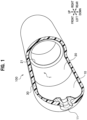
- a pressure vessel 100 includes a hollow pressure vessel liner 1, fill necks 11, and a reinforcing layer 30.
- the pressure vessel 100 is a vessel to store therein gas such as hydrogen.
- the fill necks 11 are provided at both of right and left ends, through which gas is injected and discharged.
- the reinforcing layer 30 is provided over an outer periphery of the pressure vessel liner 1, to reinforce the pressure vessel liner 1.
- the reinforcing layer 30 is made of fiber-reinforced resin, for example.
- the reinforcing layer 30 is formed by winding reinforcing fiber (not shown), impregnated with a thermosetting resin, around the pressure vessel liner 1 and curing the thermosetting resin. Glass fiber, carbon fiber, aramid fiber, or the like can be used as the reinforcing fiber of the reinforcing layer 30.
- the pressure vessel liner 1 includes first liner members 10, made of resin, and a second liner member 20 made of resin.
- the pressure vessel liner 1 is segmented into three parts in a longitudinal direction thereof (right-left direction in FIG. 1 ), with the first liner members 10 joined with the second liner member 20.
- the inside of the pressure vessel liner 1 serves as a storage space for storing gas.
- the first liner member 10 has a dome shape and is provided, at a top thereof, with the fill neck 11. One end of the first liner member 10 is open and the other end narrows so as to be gradually reduced in diameter. That is, the first liner member 10 is formed in a bottomed cylindrical shape, with one end opening. Note that the first liner member 10 is not limited to one having a cylindrical shape as described above.
- the fill neck 11 is made of metal such as stainless steel.
- the fill neck 11 has a part, such as a valve assembly, connected thereto at an opening thereof.
- the valve assembly communicates the storage space with an external gas flow path.
- the present embodiment has the fill necks 11 provided at both ends of the pressure vessel liner 1, but may have the fill neck 11 provided only at one end.
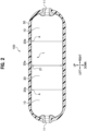
- the second liner member 20 is open at both ends in an axial direction thereof and has a cylindrical shape.
- the second liner member 20 is formed, circumferentially on an inner peripheral surface thereof, with a reinforcing rib 21 at around a midsection 20a in the axial direction thereof.
- the second liner member 20 has a shape substantially line-symmetric with respect to the reinforcing rib 21.
- the reinforcing rib 21 has a ring shape in the present embodiment.
- the reinforcing rib 21 is continuously formed in the circumferential direction, with a constant wall thickness and a constant overhang length.
- the second liner member 20 has the wall thickness formed so as to be the thickest at around the midsection 20a and gradually become thinner toward both ends 20b in the axial direction thereof.
- the first liner members 10 and the second liner member 20 are joined to each other at joint sections A, with their ends facing each other.
- the joint sections A are circumferentially formed. Away of joining is not particularly limited, but the present embodiment uses welding for the joining.
- the method for manufacturing a pressure vessel liner includes a molding step and a joining step.
- the first liner member 10 and the second liner member 20 are each molded by injection molding.
- the first liner member 10 is molded using a first-liner-member molding die (not shown).
- the second liner member 20 is molded using a second-liner-member molding die 40.
- the second-liner-member molding die 40 is composed of a first molding die 41, as a concave die, and a second molding die 42 as a convex die.
- the second molding die 42 is fitted into the first mold die 41, to define a cavity 22 and a gate 23.
- the cavity 22 is a cylindrical space. Distances L from a center to both ends in the axial direction of the cavity 22 are equal to each other.
- the cavity 22 has a distance between walls (height of the space) gradually decreasing from the center toward both ends. More in detail, a diameter of an outer wall for the cavity 22 is constant in the axial direction. In contrast, a diameter of an inner wall for the cavity 22 gradually increases from the center toward both ends in the axial direction. That is, an inner peripheral surface 22b in the cavity 22 is inclined so as to be gradually closer to an outer peripheral surface 22a from the center toward both ends.
- the gate 23 is where molten resin is injected into the cavity 22.
- the gate 23 includes a linear section 23a and a disk section 23b.
- the linear section 23a is a linear space.
- the disk section 23b is a disk-shaped space continuous to an end of the straight section 23a.
- the disk section 23b is perpendicular to the straight section 23a. Additionally, the disk section 23b communicates, at an outer peripheral edge thereof, with the cavity 22 at the center.
- molten resin is injected through the straight section 23a of the gate 23, as indicated by an arrow in FIG. 3 .
- the second-liner-member molding die 40 is demolded and a molded product is taken out, after the product has been cooled for a predetermined time.
- an unnecessary portion 51 is cut off from the molded product, to finish the second liner member 20, as shown in FIG. 4 .
- the unnecessary portion 51 is T-shaped in cross section.
- the second liner member 20 has an outer peripheral surface 20c thereof formed to have a constant outer diameter in the axial direction thereof.
- the second liner member 20 has an inner peripheral surface 20d thereof formed to have an inner diameter gradually increasing from the midsection 20a toward both ends 20b.
- first liner members 10 are joined with the second liner member 20.
- a way of joining is not particularly limited, but welding (vibration welding) is used in the present embodiment for the joining. In this manner, the ends of the first liner members 10 and the ends of the second liner member 20 are joined with each other circumferentially at the joint sections A. This completes the pressure vessel liner 1.
- the method for manufacturing the pressure vessel liner is not limited to the method described above.
- injection molding has been used in the molding step, but another molding such as rotational molding and blow molding may be used.
- a conventional molding method has been using a second-liner-member molding die 40A including a first molding die 41A, as a concave die, and a second molding die 42A as a convex die.
- the second-liner-member molding die 40A has a gate 23A, through which molten resin is injected, provided off-center toward one end of the cavity 22A.
- a pressure vessel liner may have a difference or differences in surface level at one or more sections on a surface thereof, when the second liner member is joined with the first liner members, to have strength thereof decreased.
- the second liner member 20 has the wall thickness thereof gradually decreasing from the midsection 20a toward both ends in the axial direction thereof, to allow for uniforming holding pressure in injection molding at said both ends, so that the second liner member 20 has its molding accuracy improved at said both ends.
- This allows for eliminating or reducing a difference in surface level (difference in diameter) at the joint sections A between the first liner members 10 and the second liner member 20, so that stress concentration is avoided at the joint sections A, to have increased strength of the pressure vessel liner.
- the second liner member 20 has the inner peripheral surface inclined and the wall thickness gradually decreasing, from the midsection 20a toward both ends in the axial direction thereof (i.e., has a draft angle), and this facilitates taking out a molded product, when released from the second-liner-member molding die 40, to help molding accuracy improved.
- the second liner member 20 has the reinforcing rib 21 on the inner peripheral surface circumferentially at the midsection, and this increases the pressure vessel liner 1 in strength, to prevent buckling.
- the reinforcing rib 21 is in a ring shape and is evenly provided in a circumferential direction of the second liner member 20, to avoid stress concentration to reinforce the second liner member 20 in a well-balanced manner.
- the method for manufacturing the pressure vessel liner according to the present embodiment allows for utilizing the gates 23 to form the reinforcing rib 21. This eliminates a separate step of forming the reinforcing ribs 21, to reduce the number of work steps.
- a reinforcing rib 21A according to a first modification has a small circular hole 21a in the center and a plurality of large circular holes 21b on an upper, lower, right, and left sides of the small hole 21a, as shown in FIG. 6 .
- a reinforcing rib 21B according to a second modification has the four regularly provided small circular holes 21a in addition to the first modification in FIG. 6 , as shown in FIG. 7 .
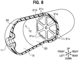
- a reinforcing rib 21C according to a third modification has the small circular hole 21a in the center and a plurality of sector-shaped holes 21c, in identical forms, around the small hole 21a, as shown in FIG. 8 .
- the reinforcing rib 21 may be suitably configured in consideration of layout balance and a flow of gas stored inside.
- the embodiment of the present invention has been described, but can be modified as required, within the scope of the present invention.
- the shape of the reinforcing rib 21 described in the embodiment is merely an example, and the present invention is not limited thereto.
- the hole in the reinforcing rib 21 may be a square hole or a slit hole, and may not have a small hole in the center.
- 100 pressure vessel
- 1 pressure vessel liner
- 10 first liner member
- 20 second liner member
- 21 reinforcement rib
- 30 reinforcing layer
Landscapes
- Engineering & Computer Science (AREA)
- Mechanical Engineering (AREA)
- Manufacturing & Machinery (AREA)
- General Engineering & Computer Science (AREA)
- Filling Or Discharging Of Gas Storage Vessels (AREA)
Applications Claiming Priority (2)
| Application Number | Priority Date | Filing Date | Title |
|---|---|---|---|
| JP2021096316 | 2021-06-09 | ||
| PCT/JP2022/022055 WO2022259906A1 (ja) | 2021-06-09 | 2022-05-31 | 圧力容器用ライナー及び圧力容器用ライナーの製造方法 |
Publications (3)
| Publication Number | Publication Date |
|---|---|
| EP4354012A1 true EP4354012A1 (de) | 2024-04-17 |
| EP4354012A4 EP4354012A4 (de) | 2025-05-21 |
| EP4354012B1 EP4354012B1 (de) | 2025-12-24 |
Family
ID=84424940
Family Applications (1)
| Application Number | Title | Priority Date | Filing Date |
|---|---|---|---|
| EP22820088.7A Active EP4354012B1 (de) | 2021-06-09 | 2022-05-31 | Druckbehälterauskleidung und verfahren zur herstellung einer druckbehälterauskleidung |
Country Status (5)
| Country | Link |
|---|---|
| US (1) | US12305810B2 (de) |
| EP (1) | EP4354012B1 (de) |
| JP (1) | JP7432062B2 (de) |
| CN (1) | CN117460910B (de) |
| WO (1) | WO2022259906A1 (de) |
Families Citing this family (2)
| Publication number | Priority date | Publication date | Assignee | Title |
|---|---|---|---|---|
| US20200347992A1 (en) * | 2019-05-02 | 2020-11-05 | Agility Fuel Systems Llc | Polymeric liner based gas cylinder with reduced permeability |
| US12358365B1 (en) | 2021-05-07 | 2025-07-15 | Agility Fuel Systems Llc | Vehicles having composite interwoven gas containment assemblies |
Family Cites Families (17)
| Publication number | Priority date | Publication date | Assignee | Title |
|---|---|---|---|---|
| US4394929A (en) * | 1981-04-10 | 1983-07-26 | Union Carbide Corporation | Cryogenic liquid storage container having an improved access conduit |
| JPH05346197A (ja) * | 1992-06-10 | 1993-12-27 | Kobe Steel Ltd | 繊維強化プラスチック複合圧力容器 |
| JP2002188794A (ja) * | 2000-12-21 | 2002-07-05 | Honda Motor Co Ltd | 高圧水素タンクおよび高圧水素タンクの製造方法 |
| JP4393155B2 (ja) * | 2003-10-30 | 2010-01-06 | 株式会社豊田自動織機 | 圧力容器 |
| CA2598621C (en) * | 2005-03-02 | 2010-10-26 | Toyota Jidosha Kabushiki Kaisha | Gas container and method of producing the same |
| JP4466408B2 (ja) * | 2005-03-02 | 2010-05-26 | トヨタ自動車株式会社 | ガス容器およびその製造方法 |
| JP2006247892A (ja) * | 2005-03-08 | 2006-09-21 | Toyota Motor Corp | 二部材の接合構造および接合方法、並びにガス容器およびその製造方法 |
| JP5072346B2 (ja) | 2006-12-27 | 2012-11-14 | 旭化成メディカル株式会社 | 体液処理器用の筒状容器及び体液処理器及び体液処理器用の筒状容器を成型する方法 |
| US7901576B2 (en) * | 2007-08-06 | 2011-03-08 | Enpress, L.L.C. | Composite water treatment vessel including liquid distributor plates |
| FR2922993B1 (fr) * | 2007-10-24 | 2010-02-26 | Michelin Soc Tech | Reservoir de fluide sous pression et methode de fabrication d'un tel reservoir. |
| JP2011027161A (ja) * | 2009-07-24 | 2011-02-10 | Toyota Motor Corp | 樹脂ライナ、および、流体容器 |
| US9376049B2 (en) * | 2011-08-22 | 2016-06-28 | Tranzgaz Inc. | Method of fabricating type 4 cylinders and arranging in transportation housings for transport of gaseous fluids |
| JP5936642B2 (ja) | 2013-04-17 | 2016-06-22 | 豊田合成株式会社 | 圧力容器用ライナー、その成形型、および圧力容器 |
| JP2016183709A (ja) | 2015-03-26 | 2016-10-20 | 株式会社明治ゴム化成 | 高圧ガス貯蔵容器とその製造方法 |
| JP6468174B2 (ja) * | 2015-12-09 | 2019-02-13 | トヨタ自動車株式会社 | 高圧タンク |
| US10816138B2 (en) * | 2017-09-15 | 2020-10-27 | Goodrich Corporation | Manufacture of a conformable pressure vessel |
| CN113733450B (zh) * | 2021-09-08 | 2023-03-31 | 亚普汽车部件股份有限公司 | 一种高压复合储氢瓶的焊接塑料内胆结构及成型工艺 |
-
2022
- 2022-05-31 CN CN202280038972.2A patent/CN117460910B/zh active Active
- 2022-05-31 JP JP2023527627A patent/JP7432062B2/ja active Active
- 2022-05-31 EP EP22820088.7A patent/EP4354012B1/de active Active
- 2022-05-31 US US18/568,098 patent/US12305810B2/en active Active
- 2022-05-31 WO PCT/JP2022/022055 patent/WO2022259906A1/ja not_active Ceased
Also Published As
| Publication number | Publication date |
|---|---|
| JPWO2022259906A1 (de) | 2022-12-15 |
| JP7432062B2 (ja) | 2024-02-15 |
| CN117460910A (zh) | 2024-01-26 |
| EP4354012B1 (de) | 2025-12-24 |
| WO2022259906A1 (ja) | 2022-12-15 |
| US20240263741A1 (en) | 2024-08-08 |
| EP4354012A4 (de) | 2025-05-21 |
| CN117460910B (zh) | 2024-03-29 |
| US12305810B2 (en) | 2025-05-20 |
Similar Documents
| Publication | Publication Date | Title |
|---|---|---|
| EP4354012A1 (de) | Druckbehälterauskleidung und verfahren zur herstellung einer druckbehälterauskleidung | |
| US9377162B2 (en) | Pressure vessel liner, molding die thereof, and pressure vessel | |
| US9956712B2 (en) | Method for producing a pressure accumulator, and pressure accumulator | |
| KR102364916B1 (ko) | 일체형 배플을 갖는 탱크 보강물 | |
| US11441732B2 (en) | Manufacturing method for high-pressure tank and high-pressure tank | |
| US20210404603A1 (en) | Compressed gas storage unit with preformed endcaps | |
| US11262024B2 (en) | High pressure tank and method of manufacturing same | |
| US11852298B2 (en) | High-pressure gas tank and method for manufacturing high-pressure gas tank | |
| JP7347362B2 (ja) | 補強層の製造方法 | |
| US11529780B2 (en) | Manufacturing method for high-pressure tank | |
| US20050006394A1 (en) | High-pressure gas container | |
| JP2023003533A (ja) | 高圧容器及びその製造方法 | |
| JP2013228082A (ja) | 圧力容器 | |
| JP2010266029A (ja) | 高圧ガスタンク | |
| JP2022187796A (ja) | 高圧タンク、及び、その製造方法 | |
| JP2017144657A (ja) | ライナーの製造方法 | |
| US8623267B2 (en) | Pressure vessel | |
| US12203596B2 (en) | High-pressure tank and method for manufacturing high-pressure tank | |
| JPWO2022259906A5 (de) | ||
| JP2021032312A (ja) | 高圧タンク | |
| JP6733228B2 (ja) | 圧力容器 | |
| US11433583B2 (en) | Method of manufacturing resin pipe | |
| KR20230040241A (ko) | 고압 저장 용기 및 그 제조 방법 | |
| KR20230040243A (ko) | 고압 저장 용기 및 그 제조 방법 | |
| KR102793829B1 (ko) | 고압 저장 용기 및 그 제조 방법 |
Legal Events
| Date | Code | Title | Description |
|---|---|---|---|
| STAA | Information on the status of an ep patent application or granted ep patent |
Free format text: STATUS: THE INTERNATIONAL PUBLICATION HAS BEEN MADE |
|
| PUAI | Public reference made under article 153(3) epc to a published international application that has entered the european phase |
Free format text: ORIGINAL CODE: 0009012 |
|
| STAA | Information on the status of an ep patent application or granted ep patent |
Free format text: STATUS: REQUEST FOR EXAMINATION WAS MADE |
|
| 17P | Request for examination filed |
Effective date: 20240109 |
|
| AK | Designated contracting states |
Kind code of ref document: A1 Designated state(s): AL AT BE BG CH CY CZ DE DK EE ES FI FR GB GR HR HU IE IS IT LI LT LU LV MC MK MT NL NO PL PT RO RS SE SI SK SM TR |
|
| DAV | Request for validation of the european patent (deleted) | ||
| DAX | Request for extension of the european patent (deleted) | ||
| REG | Reference to a national code |
Ref country code: DE Ref legal event code: R079 Free format text: PREVIOUS MAIN CLASS: F17C0001160000 Ref country code: DE Ref legal event code: R079 Ref document number: 602022027555 Country of ref document: DE Free format text: PREVIOUS MAIN CLASS: F17C0001160000 Ipc: F17C0001060000 |
|
| A4 | Supplementary search report drawn up and despatched |
Effective date: 20250423 |
|
| RIC1 | Information provided on ipc code assigned before grant |
Ipc: B29C 45/26 20060101ALI20250415BHEP Ipc: B29D 22/00 20060101ALI20250415BHEP Ipc: B29C 45/17 20060101ALI20250415BHEP Ipc: B29C 65/06 20060101ALI20250415BHEP Ipc: B29C 45/00 20060101ALI20250415BHEP Ipc: F16J 12/00 20060101ALI20250415BHEP Ipc: F17C 1/06 20060101AFI20250415BHEP |
|
| GRAP | Despatch of communication of intention to grant a patent |
Free format text: ORIGINAL CODE: EPIDOSNIGR1 |
|
| STAA | Information on the status of an ep patent application or granted ep patent |
Free format text: STATUS: GRANT OF PATENT IS INTENDED |
|
| RIC1 | Information provided on ipc code assigned before grant |
Ipc: F17C 1/06 20060101AFI20250930BHEP Ipc: F16J 12/00 20060101ALI20250930BHEP Ipc: B29C 45/00 20060101ALI20250930BHEP Ipc: B29C 65/06 20060101ALI20250930BHEP Ipc: B29C 45/17 20060101ALI20250930BHEP Ipc: B29D 22/00 20060101ALI20250930BHEP Ipc: B29C 45/26 20060101ALI20250930BHEP |
|
| INTG | Intention to grant announced |
Effective date: 20251014 |
|
| RIN1 | Information on inventor provided before grant (corrected) |
Inventor name: HAKAMATA, YASUYUKI Inventor name: KAMIYA, KEN Inventor name: YOSHIOKA, JUNYA Inventor name: YASHIMA, AKIHIRO |
|
| GRAS | Grant fee paid |
Free format text: ORIGINAL CODE: EPIDOSNIGR3 |
|
| GRAA | (expected) grant |
Free format text: ORIGINAL CODE: 0009210 |
|
| STAA | Information on the status of an ep patent application or granted ep patent |
Free format text: STATUS: THE PATENT HAS BEEN GRANTED |
|
| AK | Designated contracting states |
Kind code of ref document: B1 Designated state(s): AL AT BE BG CH CY CZ DE DK EE ES FI FR GB GR HR HU IE IS IT LI LT LU LV MC MK MT NL NO PL PT RO RS SE SI SK SM TR |
|
| REG | Reference to a national code |
Ref country code: CH Ref legal event code: F10 Free format text: ST27 STATUS EVENT CODE: U-0-0-F10-F00 (AS PROVIDED BY THE NATIONAL OFFICE) Effective date: 20251224 Ref country code: GB Ref legal event code: FG4D |
|
| REG | Reference to a national code |
Ref country code: DE Ref legal event code: R096 Ref document number: 602022027555 Country of ref document: DE |
|
| REG | Reference to a national code |
Ref country code: LT Ref legal event code: MG9D |
|
| PG25 | Lapsed in a contracting state [announced via postgrant information from national office to epo] |
Ref country code: NO Free format text: LAPSE BECAUSE OF FAILURE TO SUBMIT A TRANSLATION OF THE DESCRIPTION OR TO PAY THE FEE WITHIN THE PRESCRIBED TIME-LIMIT Effective date: 20260324 |
|
| PG25 | Lapsed in a contracting state [announced via postgrant information from national office to epo] |
Ref country code: FI Free format text: LAPSE BECAUSE OF FAILURE TO SUBMIT A TRANSLATION OF THE DESCRIPTION OR TO PAY THE FEE WITHIN THE PRESCRIBED TIME-LIMIT Effective date: 20251224 Ref country code: HR Free format text: LAPSE BECAUSE OF FAILURE TO SUBMIT A TRANSLATION OF THE DESCRIPTION OR TO PAY THE FEE WITHIN THE PRESCRIBED TIME-LIMIT Effective date: 20251224 |
|
| PG25 | Lapsed in a contracting state [announced via postgrant information from national office to epo] |
Ref country code: RS Free format text: LAPSE BECAUSE OF FAILURE TO SUBMIT A TRANSLATION OF THE DESCRIPTION OR TO PAY THE FEE WITHIN THE PRESCRIBED TIME-LIMIT Effective date: 20260324 |
|
| PG25 | Lapsed in a contracting state [announced via postgrant information from national office to epo] |
Ref country code: LV Free format text: LAPSE BECAUSE OF FAILURE TO SUBMIT A TRANSLATION OF THE DESCRIPTION OR TO PAY THE FEE WITHIN THE PRESCRIBED TIME-LIMIT Effective date: 20251224 |