EP4354069A1 - Échangeur de chaleur et unité extérieure - Google Patents
Échangeur de chaleur et unité extérieure Download PDFInfo
- Publication number
- EP4354069A1 EP4354069A1 EP21944969.1A EP21944969A EP4354069A1 EP 4354069 A1 EP4354069 A1 EP 4354069A1 EP 21944969 A EP21944969 A EP 21944969A EP 4354069 A1 EP4354069 A1 EP 4354069A1
- Authority
- EP
- European Patent Office
- Prior art keywords
- heat transfer
- opening
- transfer tube
- auxiliary
- insertion portion
- Prior art date
- Legal status (The legal status is an assumption and is not a legal conclusion. Google has not performed a legal analysis and makes no representation as to the accuracy of the status listed.)
- Withdrawn
Links
Images













Classifications
-
- F—MECHANICAL ENGINEERING; LIGHTING; HEATING; WEAPONS; BLASTING
- F28—HEAT EXCHANGE IN GENERAL
- F28D—HEAT-EXCHANGE APPARATUS, NOT PROVIDED FOR IN ANOTHER SUBCLASS, IN WHICH THE HEAT-EXCHANGE MEDIA DO NOT COME INTO DIRECT CONTACT
- F28D1/00—Heat-exchange apparatus having stationary conduit assemblies for one heat-exchange medium only, the media being in contact with different sides of the conduit wall, in which the other heat-exchange medium is a large body of fluid, e.g. domestic or motor car radiators
- F28D1/02—Heat-exchange apparatus having stationary conduit assemblies for one heat-exchange medium only, the media being in contact with different sides of the conduit wall, in which the other heat-exchange medium is a large body of fluid, e.g. domestic or motor car radiators with heat-exchange conduits immersed in the body of fluid
- F28D1/04—Heat-exchange apparatus having stationary conduit assemblies for one heat-exchange medium only, the media being in contact with different sides of the conduit wall, in which the other heat-exchange medium is a large body of fluid, e.g. domestic or motor car radiators with heat-exchange conduits immersed in the body of fluid with tubular conduits
- F28D1/053—Heat-exchange apparatus having stationary conduit assemblies for one heat-exchange medium only, the media being in contact with different sides of the conduit wall, in which the other heat-exchange medium is a large body of fluid, e.g. domestic or motor car radiators with heat-exchange conduits immersed in the body of fluid with tubular conduits the conduits being straight
- F28D1/0535—Heat-exchange apparatus having stationary conduit assemblies for one heat-exchange medium only, the media being in contact with different sides of the conduit wall, in which the other heat-exchange medium is a large body of fluid, e.g. domestic or motor car radiators with heat-exchange conduits immersed in the body of fluid with tubular conduits the conduits being straight the conduits having a non-circular cross-section
- F28D1/05366—Assemblies of conduits connected to common headers, e.g. core type radiators
- F28D1/05383—Assemblies of conduits connected to common headers, e.g. core type radiators with multiple rows of conduits or with multi-channel conduits
-
- F—MECHANICAL ENGINEERING; LIGHTING; HEATING; WEAPONS; BLASTING
- F28—HEAT EXCHANGE IN GENERAL
- F28F—DETAILS OF HEAT-EXCHANGE AND HEAT-TRANSFER APPARATUS, OF GENERAL APPLICATION
- F28F1/00—Tubular elements; Assemblies of tubular elements
- F28F1/02—Tubular elements of cross-section which is non-circular
- F28F1/022—Tubular elements of cross-section which is non-circular with multiple channels
-
- F—MECHANICAL ENGINEERING; LIGHTING; HEATING; WEAPONS; BLASTING
- F28—HEAT EXCHANGE IN GENERAL
- F28F—DETAILS OF HEAT-EXCHANGE AND HEAT-TRANSFER APPARATUS, OF GENERAL APPLICATION
- F28F1/00—Tubular elements; Assemblies of tubular elements
- F28F1/02—Tubular elements of cross-section which is non-circular
- F28F1/025—Tubular elements of cross-section which is non-circular with variable shape, e.g. with modified tube ends, with different geometrical features
-
- F—MECHANICAL ENGINEERING; LIGHTING; HEATING; WEAPONS; BLASTING
- F28—HEAT EXCHANGE IN GENERAL
- F28F—DETAILS OF HEAT-EXCHANGE AND HEAT-TRANSFER APPARATUS, OF GENERAL APPLICATION
- F28F9/00—Casings; Header boxes; Auxiliary supports for elements; Auxiliary members within casings
- F28F9/02—Header boxes; End plates
- F28F9/0219—Arrangements for sealing end plates into casing or header box; Header box sub-elements
- F28F9/0221—Header boxes or end plates formed by stacked elements
-
- F—MECHANICAL ENGINEERING; LIGHTING; HEATING; WEAPONS; BLASTING
- F28—HEAT EXCHANGE IN GENERAL
- F28F—DETAILS OF HEAT-EXCHANGE AND HEAT-TRANSFER APPARATUS, OF GENERAL APPLICATION
- F28F9/00—Casings; Header boxes; Auxiliary supports for elements; Auxiliary members within casings
- F28F9/02—Header boxes; End plates
- F28F9/04—Arrangements for sealing elements into header boxes or end plates
- F28F9/16—Arrangements for sealing elements into header boxes or end plates by permanent joints, e.g. by rolling
-
- F—MECHANICAL ENGINEERING; LIGHTING; HEATING; WEAPONS; BLASTING
- F28—HEAT EXCHANGE IN GENERAL
- F28D—HEAT-EXCHANGE APPARATUS, NOT PROVIDED FOR IN ANOTHER SUBCLASS, IN WHICH THE HEAT-EXCHANGE MEDIA DO NOT COME INTO DIRECT CONTACT
- F28D21/00—Heat-exchange apparatus not covered by any of the groups F28D1/00 - F28D20/00
- F28D2021/0019—Other heat exchangers for particular applications; Heat exchange systems not otherwise provided for
- F28D2021/0068—Other heat exchangers for particular applications; Heat exchange systems not otherwise provided for for refrigerant cycles
- F28D2021/007—Condensers
Definitions
- the present disclosure relates to a heat exchanger including a header, and an outdoor unit including the heat exchanger.
- Patent Literature 1 discloses such a heat exchanger in which a plurality of fins connecting a plurality of heat transfer tubes located side by side in an air flow direction are provided to meander to increase the probability of contact between airflow and the fins.
- Patent Literature 1 Japanese Unexamined Patent Application Publication No. 2018-155481
- the present disclosure is made to solve such a problem and provides a heat exchanger and an outdoor unit that improve the formability of an opening of a header in which heat transfer tubes are inserted.
- a heat exchanger includes: a first heat transfer tube that has a flow passage through which refrigerant flows, the flow passage being located in the first heat transfer tube; a second heat transfer tube that has a flow passage through which refrigerant flows, the flow passage being located in the second heat transfer tube; and a header connected to an end of the first heat transfer tube in a tube axial direction and an end of the second heat transfer tube in the tube axial direction.
- the header includes a main body that allows refrigerant to flow between the first heat transfer tube and a refrigerant pipe through which refrigerant flows and between the second heat transfer tube and the refrigerant pipe, and an insertion portion shaped in a plate and that has a first opening. The first heat transfer tube and the second heat transfer tube are inserted in the first opening.
- the first heat transfer tube and the second heat transfer tube are inserted in the first opening provided in the insertion portion of the header. That is, the first opening of the insertion portion is formed to be larger than that in a case in which one heat transfer tube is inserted. Accordingly, the heat exchanger and the outdoor unit enable an improvement in the formability of the opening of the header in which the heat transfer tubes are inserted.
- Fig. 1 is a circuit diagram illustrating the refrigeration cycle apparatus 1 according to Embodiment 1. As illustrated in Fig. 1 , the refrigeration cycle apparatus 1 includes an outdoor unit 2 and an indoor unit 3.
- the outdoor unit 2 includes a compressor 5, a flow switching valve 6, the outdoor heat exchanger 7, an outdoor fan 8, and an expansion valve 9.
- the indoor unit 3 includes the outdoor heat exchanger 7 and the outdoor fan 8.
- the flow switching valve 6, the outdoor heat exchanger 7, the expansion valve 9, and the outdoor heat exchanger 7 are connected by refrigerant pipes to form a refrigerant circuit.
- the compressor 5 suctions low-temperature, low-pressure refrigerant, compresses the suctioned refrigerant into high-temperature, high-pressure refrigerant, and discharges the high-temperature, high-pressure refrigerant.
- the flow switching valve 6, which is configured to switch directions in which refrigerant flows in the refrigerant circuit, is, for example, a four-way valve.
- the outdoor heat exchanger 7 exchanges heat between refrigerant and outdoor air.
- the outdoor heat exchanger 7 functions as a condenser in a cooling operation and functions as an evaporator in a heating operation.
- the outdoor fan 8 is a device configured to send outdoor air to the outdoor heat exchanger 7.
- the expansion valve 9, which is configured to decompress and expand refrigerant, is, for example, an electronic expansion valve.
- An indoor heat exchanger 10 exchanges heat between refrigerant and indoor air.
- the indoor heat exchanger 10 functions as an evaporator in the cooling operation and functions as a condenser in the heating operation.
- An indoor fan 11, which is a device configured to send indoor air to the indoor heat exchanger 10, is, for example, a cross flow fan.
- the refrigeration cycle apparatus 1 performs the cooling operation by switching the flow switching valve 6 to connect the outdoor heat exchanger 7 and the discharge side of the compressor 5.
- refrigerant suctioned into the compressor 5 is compressed into high-temperature, high-pressure gas refrigerant by the compressor 5, and the high-temperature, high-pressure gas refrigerant is discharged.
- the high-temperature, high-pressure gas refrigerant discharged from the compressor 5 passes through the flow switching valve 6 and flows into the outdoor heat exchanger 7 functioning as a condenser.
- the refrigerant that has flowed into the outdoor heat exchanger 7 is condensed and liquified by being subjected to heat exchange with outdoor air sent by the outdoor fan 8.
- the liquid refrigerant flows into the expansion valve 9 and is decompressed and expanded into low-temperature, low-pressure two-phase gas-liquid refrigerant.
- the two-phase gas-liquid refrigerant flows into the indoor heat exchanger 10 functioning as an evaporator.
- the refrigerant that has flowed into the indoor heat exchanger 10 is evaporated and gasified by being subjected to heat exchange with indoor air sent by the indoor fan 11. In this case, the indoor air is cooled, and cooling is performed indoors. Subsequently, the evaporated low-temperature, low-pressure gas refrigerant passes through the flow switching valve 6 and is suctioned into the compressor 5.
- the refrigeration cycle apparatus 1 performs the heating operation by switching the flow switching valve 6 to connect the indoor heat exchanger 10 and the discharge side of the compressor 5.
- refrigerant suctioned into the compressor 5 is compressed into high-temperature, high-pressure gas refrigerant by the compressor 5, and the high-temperature, high-pressure gas refrigerant is discharged.
- the high-temperature, high-pressure gas refrigerant discharged from the compressor 5 passes through the flow switching valve 6 and flows into the indoor heat exchanger 10 functioning as a condenser.
- the refrigerant that has flowed into the indoor heat exchanger 10 is condensed and liquified by being subjected to heat exchange with indoor air sent by the indoor fan 11.
- the indoor air is heated, and heating is performed indoors.
- the liquid refrigerant flows into the expansion valve 9 and is decompressed and expanded into low-temperature, low-pressure two-phase gas-liquid refrigerant.
- the two-phase gas-liquid refrigerant flows into the outdoor heat exchanger 7 functioning as an evaporator.
- the refrigerant that has flowed into the outdoor heat exchanger 7 is evaporated and gasified by being subjected to heat exchange with outdoor air sent by the outdoor fan 8. Subsequently, the evaporated low-temperature, low-pressure gas refrigerant passes through the flow switching valve 6 and is suctioned into the compressor 5.
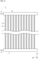
- Fig. 2 is a front view illustrating the outdoor heat exchanger 7 according to Embodiment 1.
- Fig. 3 is a side view illustrating the outdoor heat exchanger 7 according to Embodiment 1.
- Fig. 4 is a perspective view illustrating the outdoor heat exchanger 7 according to Embodiment 1.
- a white arrow in Fig. 2 represents an air flow.
- the outdoor heat exchanger 7 includes a first header 21, a second header 22, and a plurality of heat transfer tubes.
- a first heat transfer tube 23a and a second heat transfer tube 23b may be described as representatives of the plurality of heat transfer tubes.
- the first heat transfer tube 23a is a heat transfer tube of the plurality of heat transfer tubes included in the outdoor heat exchanger 7.
- the second heat transfer tube 23b is a heat transfer tube adjacent to the first heat transfer tube 23a.
- the heat transfer tubes other than the first heat transfer tube 23a and the second heat transfer tube 23b have a shape similar to that of the first heat transfer tube 23a and the second heat transfer tube 23b.
- the following description is given by using directions such as an up-down direction (Y-axis direction in each figure), a left-right direction (X-axis direction in each figure), and a front-rear direction (Z-axis direction in each figure). These directions are based on the case in which the outdoor heat exchanger 7 is disposed such that the first header 21 is located on the lower side of the outdoor heat exchanger 7, that the second header 22 is located on the upper side of the outdoor heat exchanger 7, and that the longitudinal direction of each of the first header 21 and the second header 22 is the left-right direction.
- the orientation in which the outdoor heat exchanger 7 is disposed is not limited to the above orientation.
- the first header 21 is provided in a lower part of the outdoor heat exchanger 7.
- the lower end of each of the plurality of heat transfer tubes is inserted in the top of the first header 21.
- An outflow pipe 25 is connected to a side of the first header 21.
- the outflow pipe 25 is one of the refrigerant pipes, and refrigerant that has flowed out from the outdoor heat exchanger 7 flows through the outflow pipe 25. Refrigerant flows from the plurality of heat transfer tubes collect in the first header 21 and enter the outflow pipe 25.
- the second header 22 is provided in an upper part of the outdoor heat exchanger 7.
- the upper end of each of the plurality of heat transfer tubes is inserted in the bottom of the second header 22.
- An inflow pipe 24 is connected to a side of the second header 22.
- the inflow pipe 24 is one of the refrigerant pipes, and refrigerant to flow into the outdoor heat exchanger 7 flows through the inflow pipe 24.
- the second header 22 distributes, to the plurality of heat transfer tubes, refrigerant that has flowed out from the inflow pipe 24.
- Each of the plurality of heat transfer tubes has a flow passage through which refrigerant flows, the flow passage being located in each of the plurality of heat transfer tubes.
- the ends of each of the plurality of heat transfer tubes in the tube axial direction, that is, the up-down direction, are connected to the respective headers.
- a flat tube is used as the heat transfer tube.
- the flat tube has one or a plurality of flow passages, the one or a plurality of flow passages being located in the flat tube.
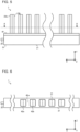
- Fig. 5 is a front view illustrating the outdoor heat exchanger 7 according to Embodiment 1.
- Fig. 5 is an enlarged view of the vicinity of the first header 21 of the outdoor heat exchanger 7.
- the first header 21 includes a main body 31 and an insertion portion 41.
- the main body 31 is shaped in a box whose top is open.
- the outflow pipe 25 is connected to a side of the main body 31.
- the insertion portion 41 is shaped in a plate, and the plurality of heat transfer tubes are inserted in the insertion portion 41.
- the insertion portion 41 is provided on the main body 31 to cover the top of the main body 31.
- the main body 31 and the insertion portion 41 may be integrally formed with each other.
- the insertion portion 41 has a plurality of openings.
- Fig. 6 is a top view illustrating the first header 21 according to Embodiment 1.
- a first opening 42a and a second opening 42b may be described as representatives of the plurality of openings.
- the first opening 42a is an opening of the plurality of openings formed in the insertion portion 41.
- the second opening 42b is an opening adjacent to the first opening 42a.
- the first opening 42a and the second opening 42b are each shaped in a rectangle.
- the openings other than the first opening 42a and the second opening 42b have a shape similar to that of the first opening 42a and the second opening 42b.
- the insertion portion 41 includes a plurality of partition portions, each of the partition portions partitioning off two openings.
- a first partition portion 43a between the first opening 42a and the second opening 42b may be described as a representative of the plurality of partition portions.
- the partition portions other than the first partition portion 43a have a shape similar to that of the first partition portion 43a.
- the parts represented by dashed lines in Fig. 6 each represent a region in which one heat transfer tube is inserted. That is, two heat transfer tubes are inserted in each of the openings of the insertion portion 41.
- Fig. 7 is a sectional view illustrating the outdoor heat exchanger 7 according to Embodiment 1.
- Fig. 7 corresponds to a section taken along A-A in Fig. 5 .
- the first heat transfer tube 23a and the second heat transfer tube 23b are inserted in the first opening 42a of the insertion portion 41.
- the first heat transfer tube 23a and the second heat transfer tube 23b are provided to be in close contact with each other. That is, the width of the first opening 42a, that is, the length of the first opening 42a in the left-right direction, is substantially equal to the sum of the width of the first heat transfer tube 23a and the width of the second heat transfer tube 23b.
- the gap between the first opening 42a and the second opening 42b that is, the width of the first partition portion 43a, is wider than that in a case in which one heat transfer tube is inserted in one opening.
- the outdoor heat exchanger 7 in Embodiment 1 the first heat transfer tube 23a and the second heat transfer tube 23b are inserted in the first opening 42a provided in the insertion portion 41 of the first header 21. That is, the first opening 42a of the insertion portion 41 is formed to be larger than that in a case in which one heat transfer tube is inserted. Accordingly, the outdoor heat exchanger 7 enables an improvement in the formability of the openings of the first header 21 in which the heat transfer tubes are inserted.
- each of the gaps between the plurality of openings is wider than that in a case in which one heat transfer tube is inserted in one opening. Accordingly, the outdoor heat exchanger 7 enables a further improvement in the formability of the openings of the first header 21 in which the heat transfer tubes are inserted. In addition, an improvement in the formability of the openings in which the heat transfer tubes are inserted enables, when the outdoor heat exchanger 7 is manufactured, achievement of various effects such as an improvement in operation efficiency, a reduction in the time for the manufacture, and a cost reduction.
- Fig. 8 is a front view illustrating an outdoor heat exchanger 7A according to a first modification example of Embodiment 1.
- Fig. 9 is a side view illustrating the outdoor heat exchanger 7A according to the first modification example of Embodiment 1.
- the plurality of heat transfer tubes each include bent portions 71.
- the bent portions 71 are provided in the vicinity of the first header 21 and the vicinity of the second header 22.
- Each bent portion 71 of the first heat transfer tube 23a and each bent portion 71 of the second heat transfer tube 23b are bent toward opposite sides in the left-right direction.
- the first heat transfer tube 23a and the second heat transfer tube 23b are disposed such that parts of the bent portions 71 thereof closer to the first header 21 are in close contact with each other and that parts of the bent portions 71 thereof closer to the second header 22 are in close contact with each other.
- a gap is formed between the bent portions 71 closer to the first header and the bent portions 71 closer to the second header 22 of the parts, exposed from the first header 21 and the second header 22, of the first heat transfer tube 23a and the second heat transfer tube 23b.
- the bent portions 71 are formed, and the heat transfer tubes are thus disposed substantially at a small pitch, thus enabling an improvement in heat exchange performance.
- Fig. 10 is a front view illustrating an outdoor heat exchanger 7B according to a second modification example of Embodiment 1.
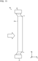
- Fig. 11 is a side view illustrating the outdoor heat exchanger 7B according to the second modification example of Embodiment 1.
- the bent portions 71 of the heat transfer tubes are inclined relative to the up-down direction, that is, the tube axial direction.
- the bent portions 71 of the heat transfer tubes closer to the first header 21 are inclined upward from the upstream side toward the downstream side in the direction in which air is sent from the outdoor fan 8, that is, from the front side toward the rear side.
- the bent portions 71 of the heat transfer tubes closer to the second header 22 are inclined downward from the upstream side toward the downstream side in the direction in which air is sent from the outdoor fan 8.
- frost may form on the parts where the bent portions 71 of the first heat transfer tube 23a and the bent portions 71 of the second heat transfer tube 23b are in contact with each other.
- the bent portions 71 are inclined relative to the tube axial direction, thus inhibiting water generated when frost is melted from remaining thereon. Water generated by melting frost is inhibited from remaining, thus enabling inhibition of refreezing of the water generated by melting frost and of impairment in heat exchange performance due to the refreezing.
- the bent portions 71 of the heat transfer tubes closer to the second header 22 are inclined downward from the upstream side toward the downstream side in the direction in which air is sent from the outdoor fan 8. Accordingly, the bent portions 71 of the heat transfer tubes closer to the second header 22 promote drainage of water generated by melting frost, thus further inhibiting refreezing of the water generated by melting frost and impairment in heat exchange performance due to the refreezing.
- the bent portions 71 closer to the first header 21 may reverse inclined directions with the bent portions 71 closer to the second header 22.
- all the bent portions 71 closer to the first header 21 and the bent portions 71 closer to the second header 22 may be formed to be inclined downward from the upstream side toward the downstream side in the direction in which air is sent.
- Fig. 12 is a front view illustrating an outdoor heat exchanger 107 according to Embodiment 2.
- Fig. 13 is a side view illustrating the outdoor heat exchanger 107 according to Embodiment 2.
- Fig. 14 is a perspective view illustrating the outdoor heat exchanger 107 according to Embodiment 2.
- the plurality of heat transfer tubes are disposed with gaps therebetween.
- the same parts as those in Embodiment 1 have the same reference signs and are not described, and description is given with a focus on the difference between Embodiments 1 and 2.
- Fig. 15 is a front view illustrating the outdoor heat exchanger 107 according to Embodiment 2.
- Fig. 15 is an enlarged view of the vicinity of the first header 21 of the outdoor heat exchanger 107.
- the header in Embodiment 2 includes an auxiliary insertion portion 51 between the insertion portion 41 and the main body 31.
- the auxiliary insertion portion 51 is shaped in a plate and is provided on the main body 31 to cover the top of the main body 31.
- the insertion portion 41 overlaps and is joined to the top of the auxiliary insertion portion 51.
- the main body 31 and the auxiliary insertion portion 51 may be integrally formed with each other.
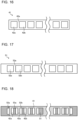
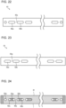
- Fig. 16 is a schematic view illustrating the insertion portion 41 according to Embodiment 2. As illustrated in Fig. 16 , the insertion portion 41 is shaped in a plate and has a plurality of openings. The insertion portion 41 is smaller in width than the auxiliary insertion portion 51. In addition, the insertion portion 41 is smaller in width than the insertion portion 41 in Embodiment 1.
- Fig. 17 is a schematic view illustrating the auxiliary insertion portion 51 according to Embodiment 2.
- the auxiliary insertion portion 51 has a plurality of auxiliary openings.
- a first auxiliary opening 52a and a second auxiliary opening 52b may be described as representatives of the plurality of auxiliary openings.
- the first auxiliary opening 52a is an auxiliary opening of the plurality of auxiliary openings formed in the auxiliary insertion portion 51.
- the second auxiliary opening 52b is an auxiliary opening adjacent to the first auxiliary opening 52a.
- the first auxiliary opening 52a and the second auxiliary opening 52b are each shaped in a rectangle.
- the openings other than the first auxiliary opening 52a and the second auxiliary opening 52b have a shape similar to that of the first auxiliary opening 52a and the second auxiliary opening 52b.
- the auxiliary insertion portion 51 includes a plurality of auxiliary partition portions, each of the auxiliary partition portions partitioning off two auxiliary openings.
- a first auxiliary partition portion 53a between the first auxiliary opening 52a and the second auxiliary opening 52b may be described as a representative of the plurality of auxiliary partition portions.
- the partition portions other than the first auxiliary partition portion 53a have a shape similar to that of the first auxiliary partition portion 53a.
- Fig. 18 is a schematic view illustrating the insertion portion 41 and the auxiliary insertion portion 51 according to Embodiment 2.
- the insertion portion 41 and the auxiliary insertion portion 51 are hatched for convenience of description.
- the first opening 42a of the insertion portion 41 is partitioned into two parts with the first auxiliary partition portion 53a of the auxiliary insertion portion 51.
- the second auxiliary opening 52b of the auxiliary insertion portion 51 is partitioned into two parts with the first partition portion 43a of the insertion portion 41.
- the plurality of openings of the insertion portion 41 and the plurality of auxiliary openings of the auxiliary insertion portion 51 have the same shape.
- the width of the first opening 42a of the insertion portion 41 is substantially equal to the sum of the width of two heat transfer tubes and the width of the first auxiliary partition portion 53a.
- the width of the second auxiliary opening 52b is substantially equal to the sum of the width of two heat transfer tubes and the width of the first partition portion 43a of the insertion portion 41.
- the length of each of the first opening 42a and the first auxiliary opening 52a in the front-rear direction is substantially equal to the length of a heat transfer tube in the front-rear direction.
- Fig. 19 is a sectional view illustrating the outdoor heat exchanger 107 according to Embodiment 2.
- Fig. 19 illustrates a section of the outdoor heat exchanger 107 corresponding to a section taken along B-B in Fig. 13 .
- the first heat transfer tube 23a is inserted in the first opening 42a of the insertion portion 41 and the first auxiliary opening 52a of the auxiliary insertion portion 51.
- the second heat transfer tube 23b is inserted in the first opening 42a of the insertion portion 41 and the second opening 42b of the auxiliary insertion portion 51. That is, the first heat transfer tube 23a is inserted in one of the two parts into which the first opening 42a of the insertion portion 41 is partitioned with the first auxiliary partition portion 53a.
- the second heat transfer tube 23b is inserted in the other of the two parts into which the first opening 42a of the insertion portion 41 is partitioned with the first auxiliary partition portion 53a. That is, also in Embodiment 2, the first heat transfer tube 23a and the second heat transfer tube 23b are inserted in the first opening 42a of the insertion portion 41.
- the outdoor heat exchanger 107 in Embodiment 2 the first heat transfer tube 23a and the second heat transfer tube 23b are inserted in the first opening 42a provided in the insertion portion 41 of the first header 21. That is, the first opening 42a of the insertion portion 41 is formed to be larger than that in a case in which one heat transfer tube is inserted. Accordingly, the outdoor heat exchanger 107 in Embodiment 2 also enables an improvement in the formability of the openings of the first header 21 in which the heat transfer tubes are inserted.
- Fig. 20 is a front view illustrating an outdoor heat exchanger 107A according to a first modification example of Embodiment 2.
- Fig. 20 is an enlarged view of the vicinity of the first header 21 of the outdoor heat exchanger 107A.
- Fig. 21 is a sectional view of the outdoor heat exchanger 107A according to the first modification example of Embodiment 2.
- Fig. 21 corresponds to a section taken along C-C in Fig. 20 .
- circular tubes are used as the heat transfer tubes.
- Fig. 22 is a schematic view illustrating the insertion portion 41 according to the first modification example of Embodiment 2.
- the openings, at respective ends in the direction in which the plurality of openings are disposed, of the plurality of openings of the insertion portion 41 are each shaped in a circle, and the openings other than the openings at the respective ends in the direction in which the plurality of openings are disposed are each shaped in a rounded rectangle.
- Fig. 23 is a schematic view illustrating the auxiliary insertion portion 51 according to the first modification example of Embodiment 2. As illustrated in Fig. 23 , the plurality of openings are each shaped in the same rounded rectangle.
- Fig. 24 is a schematic view illustrating the insertion portion 41 and the auxiliary insertion portion 51 according to the first modification example of Embodiment 2.
- the first opening 42a of the insertion portion 41 is partitioned into two parts with the first auxiliary partition portion 53a of the auxiliary insertion portion 51.
- the second auxiliary opening 52b of the auxiliary insertion portion 51 is partitioned into two parts with the first partition portion 43a of the insertion portion 41.
- the largest width of the first opening 42a of the insertion portion 41 is substantially equal to the sum of the outer diameter of two heat transfer tubes and the smallest width of the first auxiliary partition portion 53a.
- the largest width of the second auxiliary opening 52b is substantially equal to the sum of the outer diameter of two heat transfer tubes and the smallest width of the first partition portion 43a of the insertion portion 41.
- the length of each of the rounded rectangular openings of the insertion portion 41 in the front-rear direction is substantially equal to the length of a heat transfer tube in the front-rear direction.
- the diameter of each of the circular openings of the insertion portion 41 is substantially equal to the outer diameter of a heat transfer tube.
- the length of each of the auxiliary openings of the auxiliary insertion portion 51 in the front-rear direction is substantially equal to the length of a heat transfer tube in the front-rear direction.
- Fig. 25 is a sectional view illustrating the outdoor heat exchanger 107A according to the first modification example of Embodiment 2.
- the first heat transfer tube 23a is inserted in the first opening 42a of the insertion portion 41 and the first auxiliary opening 52a of the auxiliary insertion portion 51.
- the second heat transfer tube 23b is inserted in the first opening 42a of the insertion portion 41 and the second opening 42b of the auxiliary insertion portion 51. That is, as described in the first modification example of Embodiment 2, even when circular tubes are used as the heat transfer tubes, the first heat transfer tube 23a and the second heat transfer tube 23b are inserted in the first opening 42a of the insertion portion 41.
- the openings of the insertion portion 41 and the auxiliary openings of the auxiliary insertion portion 51 are combined to change in shape to fit the circular tubes, and the first heat transfer tube 23a and the second heat transfer tube 23b that are the circular tubes are thus also inserted in the first opening 42a provided in the insertion portion 41 of the first header 21. As a result, it is possible to improve the formability of the openings of the insertion portion 41.
- Fig. 26 is a schematic view illustrating the insertion portion 41 according to a second modification example of Embodiment 2.
- the insertion portion 41 has a dummy opening 44.
- the dummy opening 44 is formed side by side with the first opening 42a of the insertion portion 41.
- the dummy opening 44 is smaller in width than the first opening 42a of the insertion portion 41 and is substantially equal in width to a flat tube.
- the auxiliary insertion portion 51 has the same shape as that in Embodiment 2 and is thus not illustrated and described.
- Fig. 27 is a schematic view illustrating the insertion portion 41 and the auxiliary insertion portion 51 according to the second modification example of Embodiment 2.
- the dummy opening 44 and the first auxiliary opening 52a overlap each other.
- a dummy tube is inserted in the dummy opening 44 and the first auxiliary opening 52a.
- the dummy tube to be inserted in the dummy opening 44 may be shaped to have no flow passage through which refrigerant flows and does not have to be inserted in both the first header 21 and the second header 22.
- the shape of the dummy opening 44 may be changed as appropriate to fit the shape of a component to be inserted in the dummy opening 44.
- circular tubes may be used as the heat transfer tubes and the dummy tube.
- Fig. 28 is a schematic view illustrating the insertion portion 41 according to a third modification example of Embodiment 2.
- Fig. 29 is a schematic view illustrating the auxiliary insertion portion 51 according to the third modification example of Embodiment 2.
- the insertion portion 41 has a projection 72.
- the auxiliary insertion portion 51 has a recess 73.
- the projection 72 of the insertion portion 41 and the recess 73 of the auxiliary insertion portion 51 face each other.
- the insertion portion 41 may have the recess 73
- the auxiliary insertion portion 51 may have the projection 72.
- Circular tubes may be used as the heat transfer tubes.
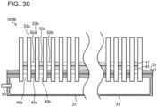
- Fig. 30 is a sectional view illustrating an outdoor heat exchanger 107B according to a fourth modification example of Embodiment 2.
- Fig. 30 illustrates a section of the outdoor heat exchanger 107B corresponding to a section taken along B-B in Fig. 13 .
- the numbers of the insertion portions 41 and the auxiliary insertion portions 51 provided are two each.
- the insertion portions 41 and the auxiliary insertion portions 51 are manufactured to form the first header 21, it is possible to increase the thickness of the first header 21, and the first header 21 is thus resistant to the pressure of refrigerant that flows in the first header 21.
- the number of the insertion portions 41 or the auxiliary insertion portions 51 to be provided may be two.
- the number of the insertion portions 41 or the auxiliary insertion portions 51 to be provided may be three or more.
- the numbers of the insertion portions 41 and the auxiliary insertion portions 51 to be provided may be three or more each.
- Fig. 31 is a sectional view illustrating an outdoor heat exchanger 107C according to a fifth modification example of Embodiment 2.
- Fig. 31 illustrates a section of the outdoor heat exchanger 107C corresponding to a section taken along B-B in Fig. 13 .
- a contact portion 61 is provided between the auxiliary insertion portion 51 and the main body 31.
- the number of the insertion portions 41 provided is two.
- the contact portion 61 is shaped in a plate and has a plurality of contact openings.
- the contact portion 61 is provided on the main body 31 to cover the top of the main body 31.
- a first contact opening 62a and a second contact opening 62b may be described as representatives of the plurality of contact openings.
- the first contact opening 62a is an opening of the plurality of contact openings formed in the contact portion 61.
- the second contact opening 62b is an opening adjacent to the first contact opening 62a.
- the first contact opening 62a and the second contact opening 62b are each shaped in a rectangle.
- the openings other than the first contact opening 62a and the second contact opening 62b have a shape similar to that of the first contact opening 62a and the second contact opening 62b.
- each of the first contact opening 62a and the second contact opening 62b is smaller than the width of each of the first auxiliary opening 52a and the second auxiliary opening 52b, that is, the length of each of the first auxiliary opening 52a and the second auxiliary opening 52b in the major axis direction.
- the length of each of the contact openings in the front-rear direction is substantially equal to the length of a heat transfer tube in the front-rear direction.
- the contact portion 61 includes a plurality of contact partition portions, each of the contact partition portions partitioning off two openings.
- a first contact partition portion 63a between the first contact opening 62a and the second contact opening 62b may be described as a representative of the plurality of contact partition portions.
- the partition portions other than the first contact partition portion 63a have a shape similar to that of the first contact partition portion 63a.
- the distance between the center of the first contact opening 62a and the center of the second contact opening 62b is equal to the distance between the center of the first auxiliary opening 52a and the center of the second auxiliary opening 52b. That is, the pitch between the plurality of auxiliary openings is equal to the pitch between the plurality of contact openings.
- the width of each of the contact openings is smaller than the width of each of the auxiliary openings. Accordingly, the first heat transfer tube 23a inserted in the first opening 42a of the insertion portion 41 is inserted also in the first opening 42a of the auxiliary insertion portion 51.
- the first heat transfer tube 23a inserted in the first opening 42a of the insertion portion 41 is not inserted in the first opening 42a of the contact portion 61 but is in contact with the top of the contact portion 61.
- the main body 31 and the contact portion 61 may be integrally formed with each other.
- circular tubes may be used as the heat transfer tubes.
- Fig. 32 is a sectional view illustrating an outdoor heat exchanger 107D according to a sixth modification example of Embodiment 2.
- Fig. 32 illustrates a section of the outdoor heat exchanger 107D corresponding to a section taken along B-B in Fig. 13 .
- Fig. 32 illustrates the case in which circular tubes are used as the heat transfer tubes and in which the numbers of the insertion portions 41 and the auxiliary insertion portions 51 provided are two each. That is, the sixth modification example of Embodiment 2 corresponds to the configuration in which the first modification example of Embodiment 2 and the fourth modification example of Embodiment 2 are combined.
- the heat transfer tubes being circular tubes
- the openings and the auxiliary openings are formed in the insertion portions 41 and the auxiliary insertion portions 51
- the insertion portions 41 and the auxiliary insertion portions 51 are manufactured to form the first header 21, it is possible to increase the thickness of the first header 21, and the first header 21 is thus resistant to the pressure of refrigerant that flows in the first header 21.
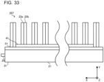
- Fig. 33 is a front view illustrating an outdoor heat exchanger 207 according to Embodiment 3. As illustrated in Fig. 33 , Embodiment 3 corresponds to the configuration in which Embodiment 1 and Embodiment 2 are combined.
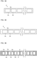
- Fig. 34 is a schematic view illustrating the insertion portion 41 according to Embodiment 3. As illustrated in Fig. 34 , the insertion portion 41 is shaped in a plate and has a plurality of openings.
- Fig. 35 is a schematic view illustrating the auxiliary insertion portion 51 according to Embodiment 3. As illustrated in Fig. 35 , the auxiliary insertion portion 51 is shaped in a plate and has a plurality of auxiliary openings.
- Fig. 36 is a schematic view illustrating the insertion portion 41 and the auxiliary insertion portion 51 according to Embodiment 3.
- the insertion portion 41 and the auxiliary insertion portion 51 are hatched for convenience of description.
- the first opening 42a of the insertion portion 41 is partitioned into two parts with the first auxiliary partition portion 53a of the auxiliary insertion portion 51.
- the second auxiliary opening 52b of the auxiliary insertion portion 51 is partitioned into two parts with the first partition portion 43a of the insertion portion 41.
- the plurality of openings of the insertion portion 41 and the plurality of auxiliary openings of the auxiliary insertion portion 51 have the same shape.
- the width of the first opening 42a is substantially equal to the sum of the width of four heat transfer tubes and the width of the first auxiliary partition portion 53a of the auxiliary insertion portion 51.
- the width of the second auxiliary opening 52b is substantially equal to the sum of the width of four heat transfer tubes and the width of the first partition portion 43a of the insertion portion 41.
- the length of each of the first opening 42a and the first auxiliary opening 52a in the front-rear direction is substantially equal to the length of a heat transfer tube in the front-rear direction.
- Fig. 37 is a sectional view illustrating the outdoor heat exchanger 207 according to Embodiment 3.
- Fig. 37 illustrates a section of the outdoor heat exchanger 207 corresponding to a section taken along B-B in Fig. 13 .
- the first heat transfer tube 23a and the second heat transfer tube 23b are inserted in the first opening 42a of the insertion portion 41 and the first auxiliary opening 52a of the auxiliary insertion portion 51.
- the first heat transfer tube 23a and the second heat transfer tube 23b are provided to be in close contact with each other.
- a third heat transfer tube 23c and a fourth heat transfer tube 23d are inserted in the first opening 42a of the insertion portion 41 and the second auxiliary opening 52b of the auxiliary insertion portion 51.
- the third heat transfer tube 23c and the fourth heat transfer tube 23d are provided to be in close contact with each other.
- the third heat transfer tube 23c is a heat transfer tube adjacent to the second heat transfer tube 23b.
- the fourth heat transfer tube 23d is a heat transfer tube adjacent to the third heat transfer tube 23c.
- the first heat transfer tube 23a and the second heat transfer tube 23b are inserted in one of the two parts into which the first opening 42a of the insertion portion 41 is partitioned with the first auxiliary partition portion 53a.
- the third heat transfer tube 23c and the fourth heat transfer tube 23d are inserted in the other of the two parts into which the first opening 42a of the insertion portion 41 is partitioned with the first auxiliary partition portion 53a. That is, in Embodiment 3, the first heat transfer tube 23a, the second heat transfer tube 23b, the third heat transfer tube 23c, and the fourth heat transfer tube 23d are inserted in the first opening 42a of the insertion portion 41.
- the outdoor heat exchanger 207 in Embodiment 3 the first heat transfer tube 23a, the second heat transfer tube 23b, the third heat transfer tube 23c, and the fourth heat transfer tube 23d are inserted in the first opening 42a provided in the insertion portion 41 of the first header 21. That is, the first opening 42a of the insertion portion 41 is formed to be larger than that in a case in which one heat transfer tube is inserted. Accordingly, the outdoor heat exchanger 207 in Embodiment 3 also enables an improvement in the formability of the openings of the first header 21 in which the heat transfer tubes are inserted.
- Fig. 38 is a front view illustrating an outdoor heat exchanger 207A according to a first modification example of Embodiment 3.
- Fig. 39 is a sectional view illustrating the outdoor heat exchanger 207A according to the first modification example of Embodiment 3.
- Fig. 39 illustrates a section of the outdoor heat exchanger 207A corresponding to a section taken along B-B in Fig. 13 .
- the plurality of heat transfer tubes each include the bent portions 71.
- the bent portions 71 are parts provided in the vicinity of the first header 21, each bent portion 71 of the first heat transfer tube 23a and each bent portion 71 of the second heat transfer tube 23b being bent toward opposite sides in the left-right direction.
- each bent portion 71 of the third heat transfer tube 23c and each bent portion 71 of the fourth heat transfer tube 23d are bent toward the opposite sides in the left-right direction.
- the first heat transfer tube 23a and the second heat transfer tube 23b are disposed such that parts of the bent portions 71 thereof closer to the first header 21 are in close contact with each other and that parts of the bent portions 71 thereof closer to the second header 22 are in close contact with each other.
- the third heat transfer tube 23c and the fourth heat transfer tube 23d are disposed such that parts of the bent portions 71 thereof closer to the first header 21 are in close contact with each other and that parts of the bent portions 71 thereof closer to the second header 22 are in close contact with each other.
- a gap is formed between the bent portions 71 closer to the first header and the bent portions 71 closer to the second header 22 of the parts, exposed from the first header 21 and the second header 22, of the first heat transfer tube 23a and the second heat transfer tube 23b.
- air flows between the first heat transfer tube 23a and the second heat transfer tube 23b.
- a gap is formed between the bent portions 71 closer to the first header and the bent portions 71 closer to the second header 22 of the parts, exposed from the first header 21 and the second header 22, of the third heat transfer tube 23c and the fourth heat transfer tube 23d.
- the bent portions 71 are formed in this manner, and the heat transfer tubes are thus disposed substantially at a small pitch, thus enabling an improvement in heat exchange performance.
- Fig. 40 is a sectional view illustrating an outdoor heat exchanger 207B according to a second modification example of Embodiment 3.
- Fig. 40 illustrates a section of the outdoor heat exchanger 207B corresponding to a section taken along B-B in Fig. 13 .
- the numbers of the insertion portions 41 and the auxiliary insertion portions 51 provided are two each.
- the insertion portions 41 and the auxiliary insertion portions 51 are manufactured to form the first header 21, it is possible to increase the thickness of the first header 21.
- the first header 21 is resistant to the pressure of refrigerant that flows in the first header 21.
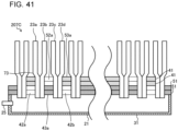
- Fig. 41 is a sectional view illustrating an outdoor heat exchanger 207C according to a third modification example of Embodiment 3.
- Fig. 41 illustrates a section of the outdoor heat exchanger 207C corresponding to a section taken along B-B in Fig. 13 .
- the plurality of heat transfer tubes each include the bent portions 71, and the numbers of the insertion portions 41 and the auxiliary insertion portions 51 provided are two each. That is, the third modification example of Embodiment 3 corresponds to the configuration in which the first modification example of Embodiment 3 and the second modification example of Embodiment 3 are combined.
- the bent portions 71 are formed, and the heat transfer tubes are thus disposed substantially at a small pitch, thus enabling an improvement in heat exchange performance.
- the openings and the auxiliary openings are formed in the insertion portions 41 and the auxiliary insertion portions 51, it is possible to reduce each thickness thereof, thus facilitating formation thereof.
- the insertion portions 41 and the auxiliary insertion portions 51 are manufactured to form the first header 21, it is possible to increase the thickness of the first header 21.
- the first header 21 is resistant to the pressure of refrigerant that flows in the first header 21.
- the insertion portion 41 and the auxiliary insertion portion 51 may have the same shape.
- An inverted insertion portion 41 is shaped to be usable as the auxiliary insertion portion 51.
- the number of kinds of header component is reduced.
- the outdoor heat exchangers including only the heat transfer tubes have been described.
- the outdoor heat exchangers may include the heat transfer tubes and fins or may be finless heat exchangers in which heat transfer tubes and fins are integrally formed with each other.
- the contents of the present disclosure are applicable to indoor heat exchangers in addition to the outdoor heat exchangers.
- the contents of the present disclosure are applicable to, in addition to the first header 21 provided in the lower part of the outdoor heat exchanger, the second header 22 provided in the upper part of the outdoor heat exchanger.
- headers that allow refrigerant to diverge that is, headers that allow refrigerant to flow directly or indirectly between a plurality of heat transfer tubes and a refrigerant pipe through which refrigerant flows.
Landscapes
- Engineering & Computer Science (AREA)
- Physics & Mathematics (AREA)
- Thermal Sciences (AREA)
- Mechanical Engineering (AREA)
- General Engineering & Computer Science (AREA)
- Geometry (AREA)
- Heat-Exchange Devices With Radiators And Conduit Assemblies (AREA)
- Other Air-Conditioning Systems (AREA)
Applications Claiming Priority (1)
| Application Number | Priority Date | Filing Date | Title |
|---|---|---|---|
| PCT/JP2021/021489 WO2022259288A1 (fr) | 2021-06-07 | 2021-06-07 | Échangeur de chaleur et unité extérieure |
Publications (1)
| Publication Number | Publication Date |
|---|---|
| EP4354069A1 true EP4354069A1 (fr) | 2024-04-17 |
Family
ID=84425939
Family Applications (1)
| Application Number | Title | Priority Date | Filing Date |
|---|---|---|---|
| EP21944969.1A Withdrawn EP4354069A1 (fr) | 2021-06-07 | 2021-06-07 | Échangeur de chaleur et unité extérieure |
Country Status (3)
| Country | Link |
|---|---|
| EP (1) | EP4354069A1 (fr) |
| JP (1) | JPWO2022259288A1 (fr) |
| WO (1) | WO2022259288A1 (fr) |
Family Cites Families (12)
| Publication number | Priority date | Publication date | Assignee | Title |
|---|---|---|---|---|
| JP2003322493A (ja) * | 2002-04-26 | 2003-11-14 | Komatsu Ltd | 熱交換器の製造方法およびその製造方法に用いられる治具並びにその製造方法により製造される熱交換器 |
| JP2004218969A (ja) * | 2003-01-16 | 2004-08-05 | Univ Tokyo | 熱交換器 |
| JP2007163004A (ja) * | 2005-12-13 | 2007-06-28 | Calsonic Kansei Corp | 熱交換器 |
| JP4830132B2 (ja) * | 2006-01-31 | 2011-12-07 | 国立大学法人 東京大学 | マイクロ熱交換器 |
| JP4811087B2 (ja) * | 2006-03-31 | 2011-11-09 | 株式会社デンソー | 熱交換器 |
| CN101915480B (zh) * | 2006-04-14 | 2014-10-29 | 三菱电机株式会社 | 热交换器及制冷空调装置 |
| JP2009121758A (ja) * | 2007-11-15 | 2009-06-04 | Mitsubishi Electric Corp | 熱交換器および冷熱システム |
| JP5287949B2 (ja) * | 2011-07-28 | 2013-09-11 | ダイキン工業株式会社 | 熱交換器 |
| JP6116702B2 (ja) * | 2013-10-30 | 2017-04-19 | 三菱電機株式会社 | 積層型ヘッダー、熱交換器、熱交換器の製造方法、及び、空気調和装置 |
| WO2018078800A1 (fr) * | 2016-10-28 | 2018-05-03 | 三菱電機株式会社 | Échangeur thermique et dispositif à cycle de réfrigération |
| JP7001917B2 (ja) | 2017-03-16 | 2022-01-20 | ダイキン工業株式会社 | 伝熱管ユニットを有する熱交換器 |
| JP7130116B2 (ja) * | 2019-04-05 | 2022-09-02 | 三菱電機株式会社 | 空気調和装置 |
-
2021
- 2021-06-07 WO PCT/JP2021/021489 patent/WO2022259288A1/fr not_active Ceased
- 2021-06-07 EP EP21944969.1A patent/EP4354069A1/fr not_active Withdrawn
- 2021-06-07 JP JP2023527133A patent/JPWO2022259288A1/ja active Pending
Also Published As
| Publication number | Publication date |
|---|---|
| JPWO2022259288A1 (fr) | 2022-12-15 |
| WO2022259288A1 (fr) | 2022-12-15 |
Similar Documents
| Publication | Publication Date | Title |
|---|---|---|
| EP3805651B1 (fr) | Unité extérieure de climatiseur et climatiseur associé | |
| US9976820B2 (en) | Stacking-type header, heat exchanger, and air-conditioning apparatus | |
| US10054368B2 (en) | Laminated header, heat exchanger, air-conditioning apparatus, and method of joining a plate-like unit of a laminated header and a pipe to each other | |
| US9702637B2 (en) | Heat exchanger, indoor unit, and refrigeration cycle apparatus | |
| EP3805687B1 (fr) | Distributeur de fluide frigorigène, échangeur de chaleur et climatiseur | |
| JP6351875B1 (ja) | 熱交換器及び冷凍サイクル装置 | |
| EP3064819A1 (fr) | Raccord de tuyaux, échangeur de chaleur et climatiseur | |
| EP4130638B1 (fr) | Échangeur de chaleur | |
| CN109923349B (zh) | 室外机及制冷循环装置 | |
| EP3699538A1 (fr) | Échangeur de chaleur et dispositif à cycle frigorifique | |
| EP3789697B1 (fr) | Échangeur de chaleur et dispositif à cycle de réfrigération | |
| US20220196345A1 (en) | Heat exchanger, method of manufacturing the same, and air-conditioning apparatus | |
| EP4155656A1 (fr) | Échangeur de chaleur et procédé de fabrication d'échangeur de chaleur | |
| US20240085116A1 (en) | Heat exchanger | |
| JP3632248B2 (ja) | 冷媒蒸発器 | |
| CN113544458B (zh) | 气体集管、热交换器以及制冷循环装置 | |
| EP4682453A1 (fr) | Échangeur de chaleur et climatiseur le comprenant | |
| US12504201B2 (en) | Air conditioner | |
| CN118009591A (zh) | 经济器集成模块 | |
| EP4365512A1 (fr) | Dispositif à cycle frigorifique | |
| EP3971507B1 (fr) | Échangeur de chaleur, et dispositif de cycle frigorifique | |
| JP7738754B2 (ja) | 熱交換器及び冷凍サイクル装置 | |
| WO2022259288A1 (fr) | Échangeur de chaleur et unité extérieure | |
| WO2021234955A1 (fr) | Échangeur de chaleur et climatiseur | |
| JP7353489B2 (ja) | 熱交換器及び冷凍サイクル装置 |
Legal Events
| Date | Code | Title | Description |
|---|---|---|---|
| STAA | Information on the status of an ep patent application or granted ep patent |
Free format text: STATUS: THE INTERNATIONAL PUBLICATION HAS BEEN MADE |
|
| PUAI | Public reference made under article 153(3) epc to a published international application that has entered the european phase |
Free format text: ORIGINAL CODE: 0009012 |
|
| STAA | Information on the status of an ep patent application or granted ep patent |
Free format text: STATUS: REQUEST FOR EXAMINATION WAS MADE |
|
| 17P | Request for examination filed |
Effective date: 20231127 |
|
| AK | Designated contracting states |
Kind code of ref document: A1 Designated state(s): AL AT BE BG CH CY CZ DE DK EE ES FI FR GB GR HR HU IE IS IT LI LT LU LV MC MK MT NL NO PL PT RO RS SE SI SK SM TR |
|
| RIC1 | Information provided on ipc code assigned before grant |
Ipc: F28F 9/02 20060101ALI20240620BHEP Ipc: F28F 9/013 20060101ALI20240620BHEP Ipc: F28F 1/02 20060101AFI20240620BHEP |
|
| STAA | Information on the status of an ep patent application or granted ep patent |
Free format text: STATUS: THE APPLICATION HAS BEEN WITHDRAWN |
|
| DAV | Request for validation of the european patent (deleted) | ||
| DAX | Request for extension of the european patent (deleted) | ||
| 18W | Application withdrawn |
Effective date: 20240814 |