EP4354149B1 - Diagnostische analysevorrichtung und vorbehandlungskarussells und zugehörige verfahren - Google Patents
Diagnostische analysevorrichtung und vorbehandlungskarussells und zugehörige verfahren Download PDFInfo
- Publication number
- EP4354149B1 EP4354149B1 EP23218057.0A EP23218057A EP4354149B1 EP 4354149 B1 EP4354149 B1 EP 4354149B1 EP 23218057 A EP23218057 A EP 23218057A EP 4354149 B1 EP4354149 B1 EP 4354149B1
- Authority
- EP
- European Patent Office
- Prior art keywords
- carousel
- reaction vessel
- examples
- track
- vessel
- Prior art date
- Legal status (The legal status is an assumption and is not a legal conclusion. Google has not performed a legal analysis and makes no representation as to the accuracy of the status listed.)
- Active
Links
Images







Classifications
-
- G—PHYSICS
- G01—MEASURING; TESTING
- G01N—INVESTIGATING OR ANALYSING MATERIALS BY DETERMINING THEIR CHEMICAL OR PHYSICAL PROPERTIES
- G01N35/00—Automatic analysis not limited to methods or materials provided for in any single one of groups G01N1/00 - G01N33/00; Handling materials therefor
- G01N35/02—Automatic analysis not limited to methods or materials provided for in any single one of groups G01N1/00 - G01N33/00; Handling materials therefor using a plurality of sample containers moved by a conveyor system past one or more treatment or analysis stations
- G01N35/025—Automatic analysis not limited to methods or materials provided for in any single one of groups G01N1/00 - G01N33/00; Handling materials therefor using a plurality of sample containers moved by a conveyor system past one or more treatment or analysis stations having a carousel or turntable for reaction cells or cuvettes
-
- G—PHYSICS
- G01—MEASURING; TESTING
- G01N—INVESTIGATING OR ANALYSING MATERIALS BY DETERMINING THEIR CHEMICAL OR PHYSICAL PROPERTIES
- G01N35/00—Automatic analysis not limited to methods or materials provided for in any single one of groups G01N1/00 - G01N33/00; Handling materials therefor
- G01N35/02—Automatic analysis not limited to methods or materials provided for in any single one of groups G01N1/00 - G01N33/00; Handling materials therefor using a plurality of sample containers moved by a conveyor system past one or more treatment or analysis stations
- G01N35/04—Details of the conveyor system
-
- G—PHYSICS
- G01—MEASURING; TESTING
- G01N—INVESTIGATING OR ANALYSING MATERIALS BY DETERMINING THEIR CHEMICAL OR PHYSICAL PROPERTIES
- G01N35/00—Automatic analysis not limited to methods or materials provided for in any single one of groups G01N1/00 - G01N33/00; Handling materials therefor
- G01N35/10—Devices for transferring samples or any liquids to, in, or from, the analysis apparatus, e.g. suction devices, injection devices
- G01N35/1002—Reagent dispensers
-
- G—PHYSICS
- G01—MEASURING; TESTING
- G01N—INVESTIGATING OR ANALYSING MATERIALS BY DETERMINING THEIR CHEMICAL OR PHYSICAL PROPERTIES
- G01N35/00—Automatic analysis not limited to methods or materials provided for in any single one of groups G01N1/00 - G01N33/00; Handling materials therefor
- G01N35/10—Devices for transferring samples or any liquids to, in, or from, the analysis apparatus, e.g. suction devices, injection devices
- G01N35/1065—Multiple transfer devices
- G01N35/1072—Multiple transfer devices with provision for selective pipetting of individual channels
-
- G—PHYSICS
- G01—MEASURING; TESTING
- G01N—INVESTIGATING OR ANALYSING MATERIALS BY DETERMINING THEIR CHEMICAL OR PHYSICAL PROPERTIES
- G01N35/00—Automatic analysis not limited to methods or materials provided for in any single one of groups G01N1/00 - G01N33/00; Handling materials therefor
- G01N35/02—Automatic analysis not limited to methods or materials provided for in any single one of groups G01N1/00 - G01N33/00; Handling materials therefor using a plurality of sample containers moved by a conveyor system past one or more treatment or analysis stations
- G01N35/04—Details of the conveyor system
- G01N2035/0439—Rotary sample carriers, i.e. carousels
- G01N2035/0453—Multiple carousels working in parallel
- G01N2035/0455—Coaxial carousels
-
- G—PHYSICS
- G01—MEASURING; TESTING
- G01N—INVESTIGATING OR ANALYSING MATERIALS BY DETERMINING THEIR CHEMICAL OR PHYSICAL PROPERTIES
- G01N35/00—Automatic analysis not limited to methods or materials provided for in any single one of groups G01N1/00 - G01N33/00; Handling materials therefor
- G01N35/02—Automatic analysis not limited to methods or materials provided for in any single one of groups G01N1/00 - G01N33/00; Handling materials therefor using a plurality of sample containers moved by a conveyor system past one or more treatment or analysis stations
- G01N35/04—Details of the conveyor system
- G01N2035/0439—Rotary sample carriers, i.e. carousels
- G01N2035/0456—Spiral tracks
-
- G—PHYSICS
- G01—MEASURING; TESTING
- G01N—INVESTIGATING OR ANALYSING MATERIALS BY DETERMINING THEIR CHEMICAL OR PHYSICAL PROPERTIES
- G01N35/00—Automatic analysis not limited to methods or materials provided for in any single one of groups G01N1/00 - G01N33/00; Handling materials therefor
- G01N35/02—Automatic analysis not limited to methods or materials provided for in any single one of groups G01N1/00 - G01N33/00; Handling materials therefor using a plurality of sample containers moved by a conveyor system past one or more treatment or analysis stations
- G01N35/04—Details of the conveyor system
- G01N2035/046—General conveyor features
- G01N2035/0465—Loading or unloading the conveyor
-
- G—PHYSICS
- G01—MEASURING; TESTING
- G01N—INVESTIGATING OR ANALYSING MATERIALS BY DETERMINING THEIR CHEMICAL OR PHYSICAL PROPERTIES
- G01N35/00—Automatic analysis not limited to methods or materials provided for in any single one of groups G01N1/00 - G01N33/00; Handling materials therefor
- G01N35/02—Automatic analysis not limited to methods or materials provided for in any single one of groups G01N1/00 - G01N33/00; Handling materials therefor using a plurality of sample containers moved by a conveyor system past one or more treatment or analysis stations
- G01N35/04—Details of the conveyor system
- G01N2035/046—General conveyor features
- G01N2035/0467—Switching points ("aiguillages")
-
- Y—GENERAL TAGGING OF NEW TECHNOLOGICAL DEVELOPMENTS; GENERAL TAGGING OF CROSS-SECTIONAL TECHNOLOGIES SPANNING OVER SEVERAL SECTIONS OF THE IPC; TECHNICAL SUBJECTS COVERED BY FORMER USPC CROSS-REFERENCE ART COLLECTIONS [XRACs] AND DIGESTS
- Y10—TECHNICAL SUBJECTS COVERED BY FORMER USPC
- Y10T—TECHNICAL SUBJECTS COVERED BY FORMER US CLASSIFICATION
- Y10T436/00—Chemistry: analytical and immunological testing
- Y10T436/11—Automated chemical analysis
- Y10T436/111666—Utilizing a centrifuge or compartmented rotor
Definitions
- the present disclosure relates generally to automated diagnostic analyzers and, more particularly, to automated diagnostic analyzers with pretreatment carousels and related methods.
- Automated diagnostic analyzers employ multiple carousels and multiple pipetting mechanisms to automatically aspirate fluid from and dispense fluid to different areas in the analyzer to perform diagnostic analysis procedures.
- Some known analyzers include a reaction vessel carousel having multiple reaction vessels and modules around the carousel to perform various functions on the reaction vessels as the carousel rotates.
- the diagnostic analyzers perform different diagnostic tests depending on the type of sample and/or the type of testing desired. Different diagnostic tests may involve different amounts of time for incubation, mixing, reading and other assay steps.
- Known analyzers that accommodate testing procedures that include relatively long and/or otherwise detailed steps that increase the duration of a test have low throughput.
- Documents US 5 856 194 A or EP 0 831 330 A2 discloses a sample analyzer.
- the analyzer has a process path, which includes a disk.
- the disk has a plurality of slots to receive containers and rotates to move the containers along a process lane for performance of a determination of an item of interest in a sample, such as blood or other bodily fluids.
- Reagents are added to the sample in the container during the determination process.
- a reagent carousel supporting a plurality of reagent containers, is located substantially concentrically with the process path and is rotatable about an axis of rotation.
- one or more reagents are aspirated from the reagent containers on the reagent carousel and dispensed into the containers on the process path.
- Specimens such as a patient's body fluids (e.g., serum, whole blood, urine, swabs, plasma, cerebra-spinal fluid, lymph fluids, tissue solids) can be analyzed using a number of different tests to provide information about the patient's health.
- body fluids e.g., serum, whole blood, urine, swabs, plasma, cerebra-spinal fluid, lymph fluids, tissue solids
- the first carousel comprises a first track of rotation and a second track of rotation.
- the example second track of rotation comprises a spiral track.
- the method includes rotating the first carousel to transport one of the first plurality of vessels along the second track.
- rotating the one of the first plurality of vessels along the second track moves the vessel from an outer radial location on the first carousel to an inner radial location on the first carousel.
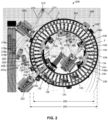
- the first and second carousels 102, 104 are rotatable within the housing 106, and the first and second carousels 102, 104 are concentric and coplanar with each other within the housing 106.
- the first carousel 102 includes a first plurality of slots 108a- n and the second carousel 104 includes a second plurality of slots 110a-n.
- the slots 108a- n , 110a- n of the respective first and second carousels 102, 104 are arranged in an annular orientation around the respective first and second carousels 102, 104.
- a first motor 114 (e.g., an electric motor, a stepper motor, a servo motor, etc.) drives the first carousel 102 and a second motor 116 drives the second carousel 104.
- the first motor 114 has a first gear 118 to engage a plurality of teeth on the inside of the first carousel 102
- the second motor 116 has a second gear 120 to engage a plurality of teeth on the outside of the second carousel 104.
- the first and second motors 114, 116 operate to rotate the first and second carousels 102, 104, respectively, independent of each other, in either direction and according to a programming and scheduling protocol of the analyzer.
- the analyzer 200 includes a first pipetting mechanism 206.
- the first pipetting mechanism 206 is coupled (e.g., mounted, fastened) to a base 208 of the analyzer 200.
- the first pipetting mechanism 206 is disposed outside of the first diameter 202 and outside of the second diameter 204 (e.g., at a distance from the center of the first carousel 102 and the center of the second carousel 104 that is greater than each of the radii of the first carousel 102 and the second carousel 104).
- the first pipetting mechanism 206 has multiple degrees of freedom.
- the third carousel 230 includes a plurality of carriers each having one or more containers (e.g., reagent containers).
- containers e.g., reagent containers
- multiple annular arrays of containers are formed (e.g., an inner annular array of containers, a middle annular array of containers, an outer annular array of containers, etc.).
- one or more containers in the outer annular array of containers include reagents (e.g., including microparticles) for diagnostic testing on the main processing track (e.g., the first carousel 102).
- one or more containers in the outer annular array of containers hold reagents for use with pretreatment processing (e.g., on the second carousel 104).
- the second pipetting mechanism 222 rotates to dispense the liquid into vessels on the second carousel 104 at point D (e.g., a pretreat reagent start position) and/or other vessels on the first carousel 102 at point E.
- the second pipetting mechanism 222 dispenses reagent into a vessel on the first or second carousel 102, 104 that has previously been loaded with a sample.
- the sample and the reagent react as the second carousel 104 rotates and, in some examples, the mixture or a portion of the mixture is aspirated (e.g., via the first pipetting mechanism 206 at point C) from the vessel on the second carousel 104 and dispensed into another vessel on the first carousel 102 for processing.
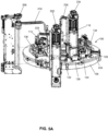
- the analyzer 200 includes a third pipetting mechanism 234.
- the third pipetting mechanism 234 is coupled to the base 208 of the analyzer 200.
- the third pipetting mechanism 234 is disposed within the bore 132 of the processing track 100 and is also disposed within the first and second diameters 202, 204.
- the third pipetting mechanism 234 is offset from an axis of rotation of the first and second carousels 102, 104.
- the third pipetting mechanism is aligned with the axis of rotation.
- the third pipetting mechanism 234 has multiple degrees of freedom.
- the third pipetting mechanism 234 has a third probe arm 236 that moves a third pipette 238 along a third path of travel 240 (e.g., a horizontal arc, a range of access) to aspirate/dispense liquid from locations along the third path of travel 240.
- the third path of travel 240 may be circular, semicircular, linear or a combination thereof.
- the third pipetting mechanism 234 is also movable in the Z direction (e.g., the vertical direction).
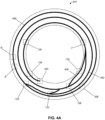
- the area in which the first diverter 122 is disposed includes a junction (e.g., an intersection) where a vessel engaged with the first track 400 can be moved radially inward and, thus, onto the second track 402.
- the first diverter 122 is a clean vessel diverter.
- a clean vessel may loaded in the outermost area of one of the slots 108a- n on the first carousel 102 with the bottom of the vessel engaged with the first track 400.
- vessels are loaded onto the first and second carousels 102, 104 via a loading mechanism 300 shown in FIG. 3 .
- the area in which the loading mechanism 300 is disposed is shown in dashed lines over the first track 400.
- a vessel moving from the first track 400 onto the second track 402 slides radially inwards in its respective slot 108a- n on the first carousel 102, which leaves the outer position of the slot 108a- n vacant. Therefore, in some examples, another vessel may be loaded into the outer position of the same slot 108a- n and be engaged with the first track 400.
- the point F is disposed on the second track 402.
- another liquid e.g., a second reagent
- the area where the second diverter 124 is disposed includes another junction (e.g., an intersection, a spur, a side track, a subtrack) that connects an outer section (e.g., an earlier section) of the second track 402 with an inner section (e.g., a later section) of the second track 402.
- the second track 402 forms a spiral that makes about two rotations.
- a vessel traveling on the second track 402 may be diverted by the second diverter 124 and moved onto another section of the second track 402 about one rotation ahead.
- the second diverter 124 is a stat diverter that accelerates the progress of a vessel along the second track 402.
- the wash zone side track 406 reconnects to the second track 402 before the area of point F, where another liquid (e.g., a second reagent) may be added to a vessel.
- another liquid e.g., a second reagent
- the second wash zone 136 is disposed over a section of the second track 402 prior to the reader 130.
- a vessel may go through two wash zones 134, 136 before a reading.
- the first and second carousels 102, 104 rotate in intervals or locksteps during a diagnostic test.
- Each interval or lockstep has an advancement step during which the carousel moves (e.g., indexes) and a stop step during which the carousel is idle.
- a plurality of functions may occur to the vessels on the first and second carousels 102, 104 such as, for example, dispensing sample, dispensing reagent, washing the contents of a reaction vessels, reading the contents of a reaction vessel, mixing the contents of a reaction vessel, etc.
- the carousels 102, 104 may have different lockstep times.
- the first carousel 102 has a lockstep time (the combination of an advancement step and a stop step) of about 18 seconds (i.e., the first carousel 102 rotates or indexes incrementally to a different position about every 18 seconds).
- the first carousel 102 moves (e.g., translates, indexes, etc.) one position in the counterclockwise direction (e.g., one position is the distance between the center of one slot to the center of the next slot).
- the second carousel 104 may rotate more or less depending on the scheduling protocols designed for the specific analyzer and/or for a particular diagnostic testing protocol.
- the advancement step of the first carousel 102 may take place during about less than one second (e.g., 400 milliseconds (ms)) of the 18 second lockstep, and the first carousel 102 may remain idle (e.g., stationary) for about 17 seconds during the stop step of the lockstep.
- the first, second and third pipetting mechanisms 206, 222, 234 aspirate and/or dispense liquids (e.g., simultaneously or in sequence), including any microparticles contained therein, and other functional modules (e.g., the reader 130, the first and second wash zones 134, 136, the ITVs 138a-e, etc.) operate around the carousels 102, 104.
- some of the functional modules also operate during the advancement step of a lockstep. In other examples, the advancement and stop times may be different.
- a vessel 112a is loaded into the slot 108a of the first carousel 102 and is positioned in the outer section of the slot 108a to engage first track 400 of the track system 244 (e.g., via the loading mechanism 300).
- the first carousel 102 moves through a plurality of locksteps, incrementally moving (e.g., indexing) the vessel 112a one position at a time in the counterclockwise direction.
- the vessel 112a reaches point B and, during this lockstep, the first pipetting mechanism 206 aspirates a liquid (e.g., a sample) and dispenses the liquid into the vessel 112a.
- the two-stage lockstep enables a reaction vessel on the second carousel 104 to be filled with a sample and a reagent, which occur at different positions (e.g., one position apart), during one lockstep of the first carousel 102 and, thus, prepared for pretreatment incubation.
- the minor lockstep occurs when a reaction vessel receives a sample (e.g., at point A) and the major lockstep occurs when the reaction vessel receives a reagent (e.g., point D).
- reagent may be dispensed in the reaction vessel, the contents of the reaction vessel may be diluted and/or the contents or portions of the content of the reaction vessel may be aspirated and transferred to a reaction vessel on the main processing carousel.
- having a two-stage lockstep sequence allows a reaction vessel on the pretreatment carousel to be prepared, which occurs at two positions, and allows the reaction vessel sufficient time for reagent dispensing and aspiration which, in some examples, involves multiple processing steps.
- a vessel 112a is deposited into one of the slots 110a- n on the second carousel 104 with the loading mechanism 300 shown in FIGS. 3 and 4 .
- the second carousel 104 goes through multiple two-stage locksteps of alternating major and minor locksteps.
- the vessel 112a is located at one position clockwise from point A ( FIG. 2 ) during a major lockstep.
- the second carousel 104 rotates one position in the counterclockwise direction such that the vessel 112a is now located at point A and held stationary.
- the first pipetting mechanism 206 may aspirate a liquid (e.g., a sample) and dispense the liquid into the vessel 112a. Then, during the next major lockstep, the second carousel 104 again rotates one position in the counterclockwise direction such that the vessel 112a is now at point D and held stationary. During this time (e.g., sixteen seconds), the second pipetting mechanism 222 aspirates another liquid (e.g., a first reagent) and dispenses the liquid into the vessel 112a. Then, during a second minor lockstep, the second carousel 104 rotates in the counterclockwise direction and again moves the vessel 112a one more position. A second major lockstep follows. This alternating sequence of minor and major locksteps may continue, and the vessel 112a is rotated around the second carousel 104.
- a liquid e.g., a sample
- the second carousel 104 again rotates one position in the counterclockwise direction such that the vessel 112
- the contents of the vessel 112a may be aspirated, via the first pipetting mechanism 206, and dispensed into another vessel on the first carousel 102 at point B.
- Such an example may be used for the purposes of incubating a sample prior to placing sample on the first carousel 102 for processing.
- the reaction has time to incubate prior to placement in a vessel on the first carousel 102 and, thus, the overall processing time of the vessels on the first carousel 102 is decreased.
- the second carousel 104 continues through more locksteps and the empty, near-empty or otherwise used vessel 112a is rotated in the counterclockwise direction. However, during this second rotation of the vessel 112a, the vessel 112a encounters point A during a major lockstep and point D during a minor lockstep. During this time, no functions are performed on the vessel 112a.
- the vessel 112a continues to rotate on the second carousel 104 and reaches the fourth diverter 128 (e.g., an active unloader) and is unloaded from its slot 110a- n on the second carousel 104.
- the fourth diverter 128 e.g., an active unloader
- the processing cycle of a given vessel on the second carousel 104 is about two full rotations. Therefore, in some examples, every other vessel on the second carousel 104 is going through the same sequencing as the vessel two slots in front or behind of that slot.
- a vessel 112a is deposited into one of the slots 110a- n on the second carousel 104 with the loading mechanism 300 shown in FIGS. 3 and 4 .
- the second carousel 104 goes through multiple two-stage locksteps of alternating major and minor locksteps.
- a sample may be dispensed into the vessel 112a.
- the vessel 112a is rotated to point D and a dilution reagent is added to the vessel 112a via the second pipetting mechanism 222.
- the dilution reagent dilutes the sample in the reaction vessel.
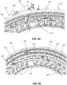
- FIGS. 4B and 4C illustrate examples of the first diverter 122 and the fourth diverter 128.
- the second and third diverters 124, 126 are similar to the first diverter 122 and, thus, will include similar components.
- the first and fourth diverters 122, 128 include respective motors 408, 410 and respective mounting brackets 412, 414.
- the motors 408, 410 are solenoids, stepper motors or servo motors.
- the mounting brackets 412, 414 may be used to mount the first and fourth diverters 122, 128 to, for example, the housing 106 ( FIG. 1 ), a cover 424 ( FIGS. 4D and 4E detailed below), the analyzer 200 ( FIG. 2 ) and/or another surface of an example analyzer.
- the first diverter 122 includes a first paddle 416 (e.g., a claw and/or aligned engagement arms) with a first channel 418.
- a reaction vessel 112a is engaged in the first paddle 416.
- a top rim 113a of the reaction vessel 112a is to slide through the first channel 418 of the first paddle 416. For example, when the reaction vessel passes 112a underneath the first diverter 122, the top rim 113a slides into the first channel 418 of the first paddle 416.
- the first paddle 416 is rotated (e.g., clockwise, counterclockwise) via the first motor 408 to align the first channel 418 and the reaction vessel 112a in a different direction to direct the reaction vessel 112a onto a chosen track.
- the first carousel 102 indexes in a plurality of locksteps, each lockstep having an advancement step and a stop step.
- the reaction vessel 112a is indexed during the advancement step into the position shown in FIG. 4B where the top rim 113a of the reaction vessel 112a is engaged with the first paddle 416.
- the first motor 408 rotates the first paddle 416 to align the top rim 113a of the reaction vessel 112a in a desired direction with an appropriate track.
- the reaction vessel 112a is indexed forward one position and, thus, the top rim 113a of the reaction vessel 112a is moved out of the first channel 418 of the first paddle 416 and along the desired track.
- the first diverter 122 rotates the first paddle 416 between about 30° to about 35°.
- the fourth diverter 128 includes a fourth paddle 420 (e.g., a claw and/or aligned engagement arms) with a fourth channel 422.
- a reaction vessel 112d is engaged in the fourth paddle 420.
- a top rim 113d of the reaction vessel 112d is to slide through the fourth channel 422 of the fourth paddle 420.
- the reaction vessel 112d passes underneath the fourth diverter 128, the top rim 113d slides into the fourth channel 422 of the fourth paddle 420.
- the fourth diverter 128 is to unload or divert the direction of the reaction vessel 112d, the fourth paddle 420 is rotated via the fourth motor 410.
- the fourth channel 422 of the fourth paddle 422 is aligned in a different direction to direct the reaction vessel 112d onto another track or off the second carousel 104.
- the second carousel 104 indexes in a plurality of locksteps, each lockstep having an advancement step and a stop step.
- the reaction vessel 112d is indexed during the advancement step into the position shown in FIG. 4B .
- the fourth diverter 128 rotates the fourth paddle 420, which rotates the reaction vessel 112d.
- the reaction vessel 112d is supported in its respective slot 110a-n by the top rim 113d and the fourth diverter 128 rotates the reaction vessel 112d until the rim 113d of the reaction vessel 112d is not supported by the second carousel 104 and falls through the slot 110a n (e.g., into a waste module).
- the fourth diverter 128 rotates the fourth paddle 420 about 90°.
- FIGS. 4D and 4E illustrate an example cover 424 (e.g., a lid, a cap) that may be used to cover the first and second carousel 102, 104 of the example processing track 100.
- the track system 244 is disposed on the bottom on the bottom of the cover 424.
- the track system 244 is grooved or otherwise formed into the bottom of the lid 424.
- the first, second, third and fourth diverters 122, 124, 126, 128 are disposed on top of the cover 424 and their respective paddles extend through the cover 424 and into the track system 244 disclosed above.
- the example processing system 600 includes a reader controller 616 that operates to control when the readings are taken.
- a reader e.g., the reader 130
- the reader may analyze the contents of the respective vessels on the carousel.
- a reaction vessel is held stationary in front of the reader for a predetermined time and a reading is taken.
- one or more reaction vessels may be passed by the reader, and the reader takes a plurality of individual readings corresponding to each reaction vessel as the reaction vessels pass.
- the example processing system 600 also includes a database 618 that may store information related to the operation of the example system 600.
- the information may include, for example, the testing protocol, reagent identification information, reagent volume information, sample identification information, position information related to a position (e.g., reaction vessel, lockstep and/or rotation) of a sample, status information related to the contents and/or position of a reaction vessel, pipette position information, carousel position information, lockstep duration information, pretreatment timing information, etc.
- the example processing system 600 also includes a user interface such as, for example, a graphical user interface (GUI) 620.
- GUI graphical user interface
- An operator or technician interacts with the processing system 600 and, thus, the analyzer 200 and/or the processing track 100 via the interface 620 to provide, for example, commands related to the testing protocols, information related to the samples to be tested, information related to the reagents or other fluids to be used in the testing, etc.
- the interface 620 may also be used by the operator to obtain information related to the status and/or results of any testing completed and/or in progress.
- the processing system components 602, 606, 608, 614, 616, 618 are communicatively coupled to other components of the example system 600 via communication links 622.
- the communication links 622 may be any type of wired connection (e.g., a databus, a USB connection, etc.) and/or any type of wireless communication (e.g., radio frequency, infrared, etc.) using any past, present or future communication protocol (e.g., Bluetooth, USB 2.0, USB 3.0, etc.).
- the components of the example system 600 may be integrated in one device or distributed over two or more devices.
- FIG. 6 While an example manner of implementing the processing track 100 and/or the analyzer 200 of FIGS. 1-5C is illustrated in FIG. 6 , one or more of the elements, processes and/or devices illustrated in FIG. 6 may be combined, divided, re-arranged, omitted, eliminated and/or implemented in any other way. Further, the example station/instrument controller 602, the example instruments 604a-n, the example processor 606, the example carousel controller 608, the example first carousel 610, the example second carousel 612, the example diverter controller 614, the example reader controller 616, the example database 618, the example graphical user interface 620 and/or, more generally, the example processing system 600 of FIG.
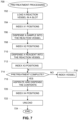
- FIGS. 7-9B Flowcharts representative of example methods 700, 800 and 900 for implementing the processing track 100, the analyzer 100 and/or the processing system 600 of FIGS. 1-6 are shown in FIGS. 7-9B .
- the methods may be implemented as machine readable instructions comprising a program for execution by a processor such as the processor 1012 shown in the example processor platform 1000 discussed below in connection with FIG. 10 .
- the program may be embodied in software stored on a tangible computer readable storage medium such as a CD-ROM, a floppy disk, a hard drive, a digital versatile disk (DVD), a Blu-ray disk, or a memory associated with the processor 1012, but the entire program and/or parts thereof could alternatively be executed by a device other than the processor 1012 and/or embodied in firmware or dedicated hardware.
- a tangible computer readable storage medium such as a CD-ROM, a floppy disk, a hard drive, a digital versatile disk (DVD), a Blu-ray disk, or a memory associated with the processor 1012, but the entire program and/or parts thereof could alternatively be executed by a device other than the processor 1012 and/or embodied in firmware or dedicated hardware.
- FIGS. 7-9B many other methods of implementing the example processing track 100, the example analyzer 200 and/or the example processing system 600 may alternatively be used. For example, the order of execution of the blocks may be changed, and/or some of the
- the example process 700 includes indexing the reaction vessel X1 positions (block 704).
- the pretreatment carousel rotates in a plurality of locksteps. During each lockstep, the pretreatment carousel indexes one position forward and remains idle for a period of time. During the period of time when the carousel is idle, different diagnostic testing functions may be performed on the reaction vessels on the pretreatment carousel. In some examples, not all of the locksteps are the same duration. In some such examples, the pretreatment carousel indexes in an alternating major and minor lockstep arrangement, where, for example, the major lockstep has a longer idle time than the minor lockstep.
- the reaction mixture is not aspirated from the reaction vessel and the reaction vessel is indexed (block 718).
- the reaction vessel continues to index (block 718) on the pretreatment carousel until the pretreatment is complete (block 714), and the reaction vessel reaches a position where the sample pipette can and is scheduled to aspirate the mixture from the reaction vessel and dispense the mixture into a vessel on the regular processing path (block 716).
- the example process 700 includes indexing the reaction vessel X4 positions (block 720).
- X4 represents the number of locksteps or index positions from the position at which the contents of the reaction vessel were removed for processing and the position at which the reaction vessel is unloaded.
- the second carousel 104 is indexed one position in the counterclockwise direction during each lockstep.
- the fourth diverter 128 is to remove reaction vessels (when scheduled to) from the second carousel 104.
- X4 is set to 24, which is the number of index positions from point C to the location of the fourth diverter 128. In this example, the reaction vessel passes through points A and D again, but during this rotation, no sample or reagent is added.
- this example is viewed from the perspective of one reaction vessel progressing through pretreatment operations on a pretreatment carousel.
- multiple other pretreatment reactions may be occurring simultaneously during the same indexes in the other slots of the pretreatment carousel and may also be performed using the process 700.
- FIG. 8 illustrates another example process 800 for diagnostic testing, which may be implemented, for example, by the example processing track 100, the example analyzer 200, and/or the example processing system 600 disclosed herein.
- the example process 800 is described from the perspective of the operations for a single vessel as the vessel rotates on a carousel of an analyzer throughout multiple locksteps. More specifically, the example process 800 may be used, for example, for preparing or pretreating a sample prior to being transferred to a processing carousel for analysis.
- the example pretreatment operations may be used, for example, in a clinical chemistry test or an immunoassay test.
- the example process 800 includes loading a reaction vessel in a slot (block 802) on the pretreatment carousel.
- a loader is disposed above and/or adjacent to the pretreatment carousel and is used to load reaction vessels into the slots of the pretreatment carousel.
- the loading mechanism 300 FIGS. 3 and 4 ) is used to load the reaction vessels into the slots 110a- n on the second carousel 104.
- the example process 800 includes indexing the reaction vessel Y1 positions (block 804).
- the pretreatment carousel rotates in a plurality locksteps in the counterclockwise direction. During each lockstep, the pretreatment carousel indexes one position forward and remains idle for a period of time. During the period of time when the carousel is idle, different diagnostic testing functions may be performed on the reaction vessels on the pretreatment carousel. In some examples, not all of the locksteps are the same duration. In some such examples, the pretreatment carousel indexes in an alternating major and minor lockstep arrangement, where, for example, the major lockstep has a longer idle time than the minor lockstep.
- Y1 represents the number of locksteps or index positions between the position at which the reaction vessel was loaded and the position at which a sample is added to the reaction vessel. In some examples, if a reaction vessel is loaded at the loading mechanism 300 ( FIGS. 3 and 4 ), the reaction vessel is indexed 41 positions till point A where, for example, a sample may be added to the reaction vessel via the first pipetting mechanism 206. Therefore, in some examples, Y1 is set to 41.
- the example process 800 includes dispensing a sample into the reaction vessel (block 806).
- a sample pipette is disposed near the pretreatment carousel to dispense sample into the reaction vessels on the pretreatment carousel.
- the first pipetting mechanism 206 is disposed outside of the processing track 100.
- the first pipetting mechanism 206 is to aspirate a sample from a sample container disposed along the first path of travel 214 and to dispense the sample into a reaction vessel on the second carousel 104 at point A. In the example shown in FIGS.
- a reaction vessel loaded on to the second carousel 104 by the loading mechanism 300 is about 41 index positions in the counterclockwise direction away from point A.
- sample may be dispensed into the reaction vessel via the first pipetting mechanism 206.
- the example process 800 also includes indexing the reaction vessel Y2 positions (block 808).
- Y2 represents the number of locksteps or index positions between the position at which sample is dispensed into the reaction vessel and the position at which a reagent or other liquid is dispensed into the reaction vessel.
- Y2 is set to one.
- the example process 800 also includes dispensing a dilution reagent(s) into the reaction vessel (810).
- a reagent pipette is disposed near the pretreatment carousel to dispense a first dilution reagent into the reaction vessels on the pretreatment carousel.
- the second pipetting mechanism 222 may be used for dispensing a dilution reagent into a reaction vessel on the second carousel 104 at point D.
- a reaction vessel loaded on to the second carousel 104 at the loading mechanism 300 is about 42 index positions in the counterclockwise direction away from point A. However, if the reaction vessel was at point A, then the reaction vessel is one index position away from point D. When a reaction vessel reaches point D, a dilution reagent may be dispensed into the reaction vessel.
- the example process 800 also includes aspirating an additional reagent (block 812).
- the reagent pipette is to aspirate another reagent from a different container.
- the second pipetting mechanism 222 may aspirate a reagent from, for example, a reagent container on the third carousel 230.
- the example process 800 includes aspirating the diluted sample/reagents from the reaction vessel (block 814). Therefore, the reagent pipette will have aspirated from both the reagent container and the reaction vessel containing the diluted sample/reagent mixture.
- the second pipetting mechanism 222 may be used for aspirating a second reagent after the second pippetting mechanism 222 has dispensed the first dilution reagent into the reaction vessel. The second pipetting mechanism 222 may then aspirate the contents (i.e., the diluted sample mixture) of the reaction vessel at point D on the second carousel 104.
- the example process 800 includes dispensing the mixture of the second reagent and the diluted sample into a reaction vessel on the processing carousel (block 816).
- the reagent pipette may be used to dispense the diluted sample and reagent mixture into a vessel on the processing carousel for processing.
- the second pipetting mechanism 222 may dispense this mixture into a reaction vessel on the first carousel 102 at point E. In some examples, this step occurs during a major lockstep to provide sufficient time for aspirating and dispensing.
- the example process 800 includes indexing the reaction vessel Y3 positions (block 818) via, for example, indexing processes disclosed herein.
- Y3 represents the number of locksteps or index positions from the position at which the diluted sample mixture or a portion thereof was removed for processing and the position at which the reaction vessel is unloaded.
- the fourth diverter 128 is to remove reaction vessels (when scheduled to) from the second carousel 104.
- Y3 may be set to eight, which is the number of index positions from point D to the location of the fourth diverter 128.
- FIGS. 9A and 9B illustrate an example diagnostic testing process 900, which may be implemented, for example, by the example processing track 100, the example analyzer 200, and/or the example processing system 600 disclosed herein.
- the example process 900 is described from the perspective of the operations for a single vessel as the vessel rotates on a processing carousel of an analyzer throughout multiple locksteps.
- the example diagnostic testing operations may be used, for example, in a clinical chemistry test or an immunoassay test.
- Example analyzers and/or processing tracks disclosed herein include a processing carousel (e.g., the first carousel 102) having a plurality of slots for receiving a plurality of reaction vessels.
- reaction vessel If the reaction vessel is in a position to receive a sample and is scheduled to receive a sample, then a sample is dispensed into the reaction vessel (block 908). If the reaction vessel is not in position to receive a sample or is not scheduled to receive a sample, no sample or diluted sample mixture is added.
- the second pipetting mechanism 222 aspirates a reagent and a diluted sample/reagent mixture from the second carousel 104 at point D and dispenses the reagent and mixture into a reaction vessel on the first carousel 102 at point E.
- the example process 900 includes indexing the reaction vessel Z3 positions (block 916).
- Z3 represents the number of locksteps or index positions between the positions (or time) at which the first reagent was added to the reaction vessel and the time the reaction vessel reaches a first diverter, which may divert the reaction vessel onto a spiral track portion of the track system.
- the example processing track 100 disclosed above includes the first diverter 122 which may divert a reaction vessel from the first track 400 to the second track 402. In such an example, the number of locksteps or index positions from point E to the location of the first diverter 122 is four. Therefore, in some examples, Z3 is set to four.
- the example process 900 includes determining if the reaction vessel is clean (block 918). If the reaction vessel is clean such as, for example, if no samples or reagents were dispensed into the reaction vessel, and the reaction vessel is not ready for processing, the reaction vessel is indexed Z4 positions (block 920). In such examples, the reaction vessel is maintained on an outer track of the track system and, thus, in the outermost radial area of the respective slot. In some examples, Z4 represents the number of locksteps or positions until the reaction vessel is in the position where the reaction vessel may receive a sample (block 906).
- the reaction vessel is diverted (block 922) onto a second track (e.g., a spiral track).
- a second track e.g., a spiral track.
- the first diverter 122 diverts reaction vessels from the first track 400 to the second track 402 to continue the diagnostic testing.
- the example process 900 includes indexing the reaction vessel Z5 positions (block 924).
- Z5 represents the number of locksteps between the first diverter (when the reaction vessel was diverted onto the second track) and a second diverter (block 926) (e.g., the stat diverter).
- the second track spirals around the processing carousel, decreasing in diameter.
- the spiral track reaches the inner portion of the first carousel 102 after two rotations on the first carousel 102.
- the stat diverter may divert the reaction vessel from one section of the second track to another section of the second track, which causes the reaction vessel to bypass a portion of the second track and, in some examples, bypass a rotation on the first carousel 102.
- the stat diverter may be used to decrease the processing time of the reaction vessel. For example, if the reaction taking place in the reaction vessel requires a longer incubation time, then the reaction vessel continues on the second track (e.g., is not a stat reaction (block 926) and is not diverted) and is indexed Z6 positions (block 928).
- Z6 represents the number of positions around the track until a third divert location (e.g., a first wash zone) (block 934).
- Z6 is the number of positions from the second diverter 124 to the third diverter 126 on the extended section of the second track 402. In some examples, Z6 may be 52.
- the example process 900 includes indexing the reaction vessel Z7 positions (block 932).
- Z7 represents the number of positions from the second diverter to a third diverter location, where a first wash zone may be accessed.
- Z7 is the number of positions from the second diverter 124 to the third diverter 126 on the shortened section of the second track 402. Therefore, in some examples, Z7 may be three.
- the example process 900 includes a third diverter which includes determining whether a first wash is desired and/or needed (block 934).
- the second track may include a third diverter to lead the reaction vessel to a first wash station where, for example, magnetic microparticle processing may occur and unwanted conjugate may be washed from the sample and magnetic microparticles.
- a first wash is desired and/or needed (block 934)
- the reaction vessel is diverted to a side track of the second track that leads to the wash zone and the contents of the reaction vessel are washed (block 936).
- the example process 900 includes indexing the reaction vessel Z8 positions (block 936). Z8 represents the positions on the side track from the third diverter to a second reagent access point, discussed in detail below.
- the third diverter 126 may divert a reaction vessel onto the wash zone side track 406 where the contents of the reaction vessel can be washed.
- Z8 may represent the locksteps or positions along the wash zone side track 406 from the third diverter 126 until the second reagent access point, e.g., point F. Therefore, in some examples, Z8 is set to 13.
- the example process includes indexing the reaction vessel Z9 positions on the processing carousel (block 940).
- Z9 represents the number of positions along the second track from the wash zone diverter to a second reagent access or dispensation point.
- the second track 402 splits at the third diverter 126 such that a reaction vessel may follow the wash zone side track 406 to be washed or may stay on the second track 402. In either path, the tracks reconnect before point F. Therefore, in some examples, Z9 is set to Z8.
- the example process 900 in FIG. 9A continues in FIG. 9B .
- the example process 900 includes determining if a second reagent is to be added to the reaction vessel (block 940).
- a second reagent pipette is disposed within the diameter of the processing carousel.
- the second reagent pipette is to aspirate a second reagent and dispense the reagent into a reaction vessel. If it is determined that a second reagent is desired, the second reagent pipette dispenses a second reagent into the reaction vessel (block 944).
- the third pipetting mechanism 234 is to aspirate a second reagent and dispense the second reagent into a reaction vessel on the first carousel 102 at point F.
- the example process 900 includes indexing the reaction vessel Z11 positions (block 950).
- Z11 represents the number of positions between the second wash zone and a position where a reading is taken.
- Z11 may represent the lockstep positions between the second wash zone 136 and the position of the reader 130.
- the example process 900 includes reading the contents of the reaction vessel (block 952).
- a reader is disposed along the processing carousel to analyze the contents of the reaction vessel. For example, during an example chemiluminescent reaction, the reader gathers photon data representative of a reaction and the contents of the reaction vessel.
- the processing carousel continues to index and another reaction vessel may be added (block 902) to the same slot and another diagnostic analysis may take place using the sample process 900.
- another reaction vessel may be added (block 902) to the same slot and another diagnostic analysis may take place using the sample process 900.
- multiple reaction vessels may be performing diagnostic analysis on a number of samples as the processing carousel rotates.
- multiple reaction vessels may be disposed within the same slot on the process carousel.
- a first reaction vessel may be engaged with the first track and be disposed in the outermost radial position in the slot
- a second reaction vessel may be engaged with the second track and be disposed in the middle area of the slot
- a third reaction vessel may be disposed in the innermost radial position in the slot.
- Each of the reaction vessels may be at different stages of diagnostic testing.
Landscapes
- Chemical & Material Sciences (AREA)
- Physics & Mathematics (AREA)
- Health & Medical Sciences (AREA)
- Life Sciences & Earth Sciences (AREA)
- Analytical Chemistry (AREA)
- Biochemistry (AREA)
- General Health & Medical Sciences (AREA)
- General Physics & Mathematics (AREA)
- Immunology (AREA)
- Pathology (AREA)
- Chemical Kinetics & Catalysis (AREA)
- Automatic Analysis And Handling Materials Therefor (AREA)
Claims (15)
- Diagnostischer Analysator (200), umfassend:ein Vorbehandlungskarussell (104), um eine erste Vielzahl von Reaktionsgefäßen zu tragen, wobei sich das Vorbehandlungskarussell (104) dreht, so dass die erste Vielzahl von Reaktionsgefäßen durch eine Vielzahl von Indexpositionen bewegt wird;ein Verarbeitungskarussell (102), um eine zweite Vielzahl von Reaktionsgefäßen zu tragen, wobei das Verarbeitungskarussell (102) koaxial mit dem Vorbehandlungskarussell (104) ist;einen ersten Pipettiermechanismus (206);einen zweiten Pipettiermechanismus (222); undeine Steuereinheit (600), die konfiguriert ist zum:Steuern des ersten Pipettiermechanismus (206), um eine Probe in ein erstes Reaktionsgefäß (112a) der ersten Vielzahl von Reaktionsgefäßen auf dem Vorbehandlungskarussell (104) abzugeben;Steuern des zweiten Pipettiermechanismus (222), um ein Reagenz in das erste Reaktionsgefäß (112a) abzugeben;Steuern des Vorbehandlungskarussells (104), um sich zu drehen, so dass das erste Reaktionsgefäß (112a) durch eine oder mehrere Indexpositionen bewegt wird; undSteuern eines von dem ersten Pipettiermechanismus (206) oder dem zweiten Pipettiermechanismus (222), um eine Mischung aus der Probe und dem Reagenz aus dem ersten Reaktionsgefäß (112a) anzusaugen und die Mischung in ein zweites Reaktionsgefäß (112b) der zweiten Vielzahl von Reaktionsgefäßen auf dem Verarbeitungskarussell (102) abzugeben.
- Diagnostischer Analysator (200) nach Anspruch 1, wobei das Vorbehandlungskarussell (104) um das Verarbeitungskarussell (102) angeordnet ist.
- Diagnostischer Analysator (200) nach Anspruch 1, wobei das Vorbehandlungskarussell (104) und das Verarbeitungskarussell (102) koplanar sind.
- Diagnostischer Analysator (200) nach Anspruch 1, wobei die Steuereinheit (600) konfiguriert ist zum:Steuern des ersten Pipettiermechanismus (206), um die Probe in das erste Reaktionsgefäß (112a) abzugeben, während das erste Reaktionsgefäß (112a) in einer ersten Indexposition ist; undSteuern des zweiten Pipettiermechanismus (222), um das Reagenz in das erste Reaktionsgefäß (112a) abzugeben, während das erste Reaktionsgefäß (112a) eine zweite Indexposition ist.
- Diagnostischer Analysator (200) nach Anspruch 4, wobei die Steuereinheit (600) konfiguriert ist zum:
Steuern des ersten Pipettiermechanismus (206), um die Mischung aus der Probe und dem Reagenz aus dem ersten Reaktionsgefäß (112a) anzusaugen, während das erste Reaktionsgefäß (112a) in einer dritten Indexposition ist. - Diagnostischer Analysator (200) nach Anspruch 4, wobei die Steuereinheit (600) konfiguriert ist zum:
Steuern des zweiten Pipettiermechanismus (222), um die Mischung aus der Probe und dem Reagenz aus dem ersten Reaktionsgefäß (112a) anzusaugen, während das erste Reaktionsgefäß (112a) in der zweiten Indexposition ist. - Diagnostischer Analysator (200) nach Anspruch 6, wobei die zweite Indexposition eine Indexposition hinter der ersten Indexposition ist.
- Diagnostischer Analysator (200) nach Anspruch 1, wobei die Steuereinheit (600) dazu konfiguriert ist, das Vorbehandlungskarussell (104) zu steuern, um sich gemäß einer ersten Gleichschrittsequenz zu drehen, die ein alternierendes Muster von Neben- und Hauptgleichschritten einschließt, wobei das Vorbehandlungskarussell (104) während jeweiliger einer der Nebengleichschritte dazu vorgesehen ist, eine Indexposition vorwärts zu indizieren und für einen ersten Zeitraum zu stoppen, und wobei das Vorbehandlungskarussell (104) während jeweiliger einer der Hauptgleichschritte dazu vorgesehen ist, eine Position vorwärts zu indizieren und für einen zweiten Zeitraum zu stoppen, wobei der zweite Zeitraum länger als der erste Zeitraum ist.
- Diagnostischer Analysator (200) nach Anspruch 8, wobei die Steuereinheit (600) konfiguriert ist zum:Steuern des ersten Pipettiermechanismus (206), um die Probe während eines der Nebengleichschritte in das erste Reaktionsgefäß (112a) abzugeben; undSteuern des zweiten Pipettiermechanismus (222), um das Reagenz während eines der Hauptgleichschritte in das erste Reaktionsgefäß (112a) abzugeben.
- Diagnostischer Analysator (200) nach Anspruch 8, wobei einer der Hauptgleichschritte und einer der Nebengleichschritte der ersten Gleichschrittsequenz eine kombinierte erste Zeitdauer aufweisen, und wobei die Steuereinheit dazu konfiguriert ist, das Verarbeitungskarussell (102) zu steuern, um sich durch eine zweite Gleichschrittsequenz zu drehen, die eine Vielzahl von Gleichschritten einschließt, wobei ein Gleichschritt der zweiten Gleichschrittsequenz eine zweite Zeitdauer aufweist, wobei die zweite Zeitdauer gleich der ersten Zeitdauer ist.
- Diagnostischer Analysator (200) nach Anspruch 1, ferner einschließend ein Lesegerät (130), das benachbart zu dem Verarbeitungskarussell (102) angeordnet ist, wobei das Lesegerät (130) zum Lesen von Inhalten der zweiten Vielzahl von Reaktionsgefäßen vorgesehen ist, während die zweite Vielzahl von Reaktionsgefäßen das Lesegerät (130) passiert.
- Diagnostischer Analysator (200) nach Anspruch 1, ferner einschließend ein Gefäßladegerät (300), um leere Reaktionsgefäße auf das Vorbehandlungskarussell (104) und das Verarbeitungskarussell (102) zu laden, und wobei das Gefäßladegerät (300) über dem Vorbehandlungskarussell (104) und dem Verarbeitungskarussell (102) angeordnet ist.
- Diagnostischer Analysator (200) nach Anspruch 1, wobei das Vorbehandlungskarussell (104) eine erste Vielzahl von Schlitzen (110a- n ) einschließt, um die erste Vielzahl von Reaktionsgefäßen zu halten, und das Verarbeitungskarussell (102) eine zweite Vielzahl von Schlitzen (108a- n ) einschließt, um die zweite Vielzahl von Reaktionsgefäßen zu halten, wobei die erste Vielzahl von Schlitzen (110a- n ) eine größere Anzahl von Schlitzen als die zweite Vielzahl von Schlitzen (108a-n) einschließt.
- Verfahren, umfassend:Drehen eines Vorbehandlungskarussells (104), um eine erste Vielzahl von Reaktionsgefäßen auf dem Vorbehandlungskarussell durch eine Vielzahl von Indexpositionen zu bewegen;Drehen eines Verarbeitungskarussells (102), um eine zweite Vielzahl von Reaktionsgefäßen, die auf dem Vorbehandlungskarussell getragen werden, zu bewegen, wobei das Verarbeitungskarussell (102) koaxial mit dem Vorbehandlungskarussell (104) ist;Abgeben einer Probe in ein erstes Reaktionsgefäß (112a) der ersten Vielzahl von Reaktionsgefäßen auf dem Vorbehandlungskarussell (104) mittels eines ersten Pipettiermechanismus (206);Abgeben eines Reagenzes in das erste Reaktionsgefäß (112a) mittels eines zweiten Pipettiermechanismus (222); undVerwenden eines von dem ersten Pipettiermechanismus (206) oder dem zweiten Pipettiermechanismus (222), um eine Mischung aus der Probe und dem Reagenz aus dem ersten Reaktionsgefäß (112a) anzusaugen und die Mischung in ein zweites Reaktionsgefäß (112b) der zweiten Vielzahl von Reaktionsgefäßen auf dem Verarbeitungskarussell (102) abzugeben.
- Verfahren nach Anspruch 14, wobei das Vorbehandlungskarussell (104) um das Verarbeitungskarussell (102) angeordnet ist.
Applications Claiming Priority (3)
| Application Number | Priority Date | Filing Date | Title |
|---|---|---|---|
| US201361792779P | 2013-03-15 | 2013-03-15 | |
| PCT/US2013/078041 WO2014149118A2 (en) | 2013-03-15 | 2013-12-27 | Diagnostic analyzers with pretreatment carousels and related methods |
| EP13824275.5A EP2972402B1 (de) | 2013-03-15 | 2013-12-27 | Diagnostische analysevorrichtung und vorbehandlungskarussells und zugehörige verfahren |
Related Parent Applications (1)
| Application Number | Title | Priority Date | Filing Date |
|---|---|---|---|
| EP13824275.5A Division EP2972402B1 (de) | 2013-03-15 | 2013-12-27 | Diagnostische analysevorrichtung und vorbehandlungskarussells und zugehörige verfahren |
Related Child Applications (1)
| Application Number | Title | Priority Date | Filing Date |
|---|---|---|---|
| EP25178240.5 Division-Into | 2025-05-22 |
Publications (3)
| Publication Number | Publication Date |
|---|---|
| EP4354149A2 EP4354149A2 (de) | 2024-04-17 |
| EP4354149A3 EP4354149A3 (de) | 2024-07-03 |
| EP4354149B1 true EP4354149B1 (de) | 2025-07-02 |
Family
ID=50001290
Family Applications (2)
| Application Number | Title | Priority Date | Filing Date |
|---|---|---|---|
| EP23218057.0A Active EP4354149B1 (de) | 2013-03-15 | 2013-12-27 | Diagnostische analysevorrichtung und vorbehandlungskarussells und zugehörige verfahren |
| EP13824275.5A Active EP2972402B1 (de) | 2013-03-15 | 2013-12-27 | Diagnostische analysevorrichtung und vorbehandlungskarussells und zugehörige verfahren |
Family Applications After (1)
| Application Number | Title | Priority Date | Filing Date |
|---|---|---|---|
| EP13824275.5A Active EP2972402B1 (de) | 2013-03-15 | 2013-12-27 | Diagnostische analysevorrichtung und vorbehandlungskarussells und zugehörige verfahren |
Country Status (6)
| Country | Link |
|---|---|
| US (2) | US10001497B2 (de) |
| EP (2) | EP4354149B1 (de) |
| JP (4) | JP6165961B2 (de) |
| CN (2) | CN105190317B (de) |
| ES (2) | ES2970108T3 (de) |
| WO (1) | WO2014149118A2 (de) |
Families Citing this family (36)
| Publication number | Priority date | Publication date | Assignee | Title |
|---|---|---|---|---|
| US9795961B1 (en) | 2010-07-08 | 2017-10-24 | National Technology & Engineering Solutions Of Sandia, Llc | Devices, systems, and methods for detecting nucleic acids using sedimentation |
| US9244065B1 (en) | 2012-03-16 | 2016-01-26 | Sandia Corporation | Systems, devices, and methods for agglutination assays using sedimentation |
| US9903001B1 (en) | 2012-07-19 | 2018-02-27 | National Technology & Engineering Solutions Of Sandia, Llc | Quantitative detection of pathogens in centrifugal microfluidic disks |
| CN105190317B (zh) | 2013-03-15 | 2018-05-04 | 雅培制药有限公司 | 具有预处理转盘的诊断分析机及相关方法 |
| US9500579B1 (en) * | 2013-05-01 | 2016-11-22 | Sandia Corporation | System and method for detecting components of a mixture including tooth elements for alignment |
| US9803238B1 (en) | 2013-11-26 | 2017-10-31 | National Technology & Engineering Solutions Of Sandia, Llc | Method and apparatus for purifying nucleic acids and performing polymerase chain reaction assays using an immiscible fluid |
| US9702871B1 (en) | 2014-11-18 | 2017-07-11 | National Technology & Engineering Solutions Of Sandia, Llc | System and method for detecting components of a mixture including a valving scheme for competition assays |
| CN104764895A (zh) * | 2015-03-19 | 2015-07-08 | 济南华天恒达科技有限公司 | 粪便样品传送盘 |
| US10254298B1 (en) | 2015-03-25 | 2019-04-09 | National Technology & Engineering Solutions Of Sandia, Llc | Detection of metabolites for controlled substances |
| EP3314269A4 (de) | 2015-06-26 | 2019-01-23 | Abbott Laboratories | Reaktionsgefässtauschervorrichtung für einen diagnostischen analysator |
| CN108027280B (zh) | 2015-06-26 | 2021-07-06 | 雅培实验室 | 用于使得反应容器在诊断分析仪中从处理轨道运动至旋转装置的反应容器运动部件 |
| EP3974828A1 (de) * | 2015-09-29 | 2022-03-30 | Haemonetics Corporation | System und verfahren zur abbildung eines rotierenden objekts |
| USD837401S1 (en) | 2016-03-22 | 2019-01-01 | Abbott Laboratories | Carrier for use in a diagnostic analyzer |
| EP3460467A4 (de) * | 2016-05-20 | 2020-04-15 | Shimadzu Corporation | Vorverarbeitungsvorrichtung und analysesystem mit der vorverarbeitungsvorrichtung |
| US10406528B1 (en) | 2016-08-04 | 2019-09-10 | National Technology & Engineering Solutions Of Sandia, Llc | Non-contact temperature control system for microfluidic devices |
| US10981174B1 (en) | 2016-08-04 | 2021-04-20 | National Technology & Engineering Solutions Of Sandia, Llc | Protein and nucleic acid detection for microfluidic devices |
| US10786811B1 (en) | 2016-10-24 | 2020-09-29 | National Technology & Engineering Solutions Of Sandia, Llc | Detection of active and latent infections with microfluidic devices and systems thereof |
| TWI645184B (zh) * | 2016-11-04 | 2018-12-21 | 財團法人工業技術研究院 | 氣膠粒子分析設備 |
| CN106771306B (zh) * | 2017-02-22 | 2018-11-09 | 长沙开元仪器股份有限公司 | 一种中空转盘式送样装置 |
| CN106980026A (zh) * | 2017-03-29 | 2017-07-25 | 盐城拜明生物技术有限公司 | 全自动化学发光免疫分析检测执行装置 |
| JP6914799B2 (ja) * | 2017-10-06 | 2021-08-04 | 日本電子株式会社 | 自動分析装置及び動作量補正方法 |
| CN109975277B (zh) * | 2017-12-28 | 2024-08-13 | 深圳市新产业生物医学工程股份有限公司 | 化学发光检测仪及其检测方法 |
| CN108627660B (zh) * | 2018-03-05 | 2022-01-07 | 广纳达康(广州)生物科技有限公司 | 用于样品前处理的容器配送装置、配送方法及前处理装置 |
| CN109230308B (zh) * | 2018-08-03 | 2020-05-19 | 迪瑞医疗科技股份有限公司 | 一种回转传动机构 |
| US11385249B2 (en) | 2018-12-04 | 2022-07-12 | Bd Kiestra B.V. | Multiple carousel cartridge-based dispensing system and method |
| USD937435S1 (en) | 2019-05-07 | 2021-11-30 | Abbott Laboratories | Carrier for use in a diagnostic analyzer |
| CN110252430B (zh) * | 2019-07-02 | 2021-05-07 | 英诺维尔智能科技(苏州)有限公司 | 一种多功能液体操作平台 |
| CN111521833B (zh) * | 2019-12-19 | 2025-09-02 | 威海威高生物科技有限公司 | 具有多反应模式的化学发光免疫分析反应盘及分析仪 |
| CN114076733B (zh) * | 2020-08-20 | 2025-04-29 | 科美诊断技术股份有限公司 | 用于化学发光检测的承载机构的运行方法 |
| CN112114159A (zh) * | 2020-10-23 | 2020-12-22 | 安图实验仪器(郑州)有限公司 | 用于反应杯温育测光的连续输送装置 |
| CN112162105B (zh) * | 2020-10-23 | 2024-07-09 | 安图实验仪器(郑州)有限公司 | 高速磁洗温育测光装置 |
| CN116413458A (zh) * | 2021-12-29 | 2023-07-11 | 重庆国科医创科技发展有限公司 | 一种温育反应盘机构 |
| CN114720710B (zh) * | 2022-04-06 | 2025-08-19 | 西安纳图智能科技有限公司 | 一种带双转盘结构的样本处理装置 |
| CN115216397A (zh) * | 2022-09-01 | 2022-10-21 | 深圳零一生命科技有限责任公司 | 一种全自动核酸提取扩增诊断一体机 |
| JP2024044534A (ja) * | 2022-09-21 | 2024-04-02 | 株式会社日立ハイテク | 自動分析装置およびその分析方法 |
| CN120447503B (zh) * | 2025-07-08 | 2025-10-14 | 四川省食品检验研究院 | 一种样品前处理中转运过程控制系统 |
Family Cites Families (350)
| Publication number | Priority date | Publication date | Assignee | Title |
|---|---|---|---|---|
| GB1149383A (en) | 1965-05-07 | 1969-04-23 | Joyce Loebl And Co Ltd | Improvements in chemical sampling methods |
| US3449959A (en) | 1966-06-27 | 1969-06-17 | Bausch & Lomb | Sample container for automatic sampling apparatus |
| US3451433A (en) | 1967-05-24 | 1969-06-24 | Sonoco Products Co | Forming tube for glass fibers |
| JPS5719667A (en) | 1980-07-10 | 1982-02-01 | Asahi Glass Co Ltd | Pretreating device for analyzer |
| JPS5868670A (ja) | 1981-10-21 | 1983-04-23 | Hitachi Ltd | 自動分折装置 |
| US5482834A (en) | 1982-05-17 | 1996-01-09 | Hahnemann University | Evaluation of nucleic acids in a biological sample hybridization in a solution of chaotrophic salt solubilized cells |
| JPS59116047A (ja) | 1982-12-22 | 1984-07-04 | Olympus Optical Co Ltd | 自動分析機の制御方法 |
| JPS6195248A (ja) | 1984-10-17 | 1986-05-14 | Hitachi Ltd | 試料認識分注装置 |
| US5071625A (en) | 1985-02-27 | 1991-12-10 | Fisher Scientific Company | Cuvette handling |
| US4738825A (en) | 1985-02-27 | 1988-04-19 | Fisher Scientific Company | Cuvette handling |
| US5656493A (en) | 1985-03-28 | 1997-08-12 | The Perkin-Elmer Corporation | System for automated performance of the polymerase chain reaction |
| JPS62863A (ja) * | 1985-06-26 | 1987-01-06 | Nippon Tectron Co Ltd | 自動分析装置 |
| US4774055A (en) | 1985-06-26 | 1988-09-27 | Japan Tectron Instruments Corporation | Automatic analysis apparatus |
| JPH0690212B2 (ja) | 1986-02-21 | 1994-11-14 | 株式会社東芝 | 自動化学分析装置 |
| JPS62228952A (ja) | 1986-03-31 | 1987-10-07 | Toshiba Corp | 自動化学分析装置における吸引吐出方法 |
| JPH0754326B2 (ja) | 1986-06-24 | 1995-06-07 | 株式会社東芝 | 自動化学分析装置 |
| US5698450A (en) | 1986-10-14 | 1997-12-16 | Ringrose; Anthony | Method for measuring antigens or antibodies in biological fluids |
| US5750338A (en) | 1986-10-23 | 1998-05-12 | Amoco Corporation | Target and background capture methods with amplification for affinity assays |
| US5714380A (en) | 1986-10-23 | 1998-02-03 | Amoco Corporation | Closed vessel for isolating target molecules and for performing amplification |
| US4849177A (en) | 1987-05-08 | 1989-07-18 | Abbott Laboratories | Reagent pack and carousel |
| US5051238A (en) | 1987-11-20 | 1991-09-24 | Hitachi, Ltd. | Automatic analyzing system |
| US5597733A (en) | 1988-07-25 | 1997-01-28 | Precision Systems, Inc. | Automatic multiple-sample multiple-reagent dispensing method in chemical analyzer |
| FR2634893B1 (fr) | 1988-07-28 | 1990-09-14 | Guigan Jean | Laboratoire miniature pour la realisation d'analyses biologiques par reaction chimique a partir d'un echantillon de sang |
| ES2085854T3 (es) | 1988-08-02 | 1996-06-16 | Abbott Lab | Metodo y dispositivo de produccion de datos de calibrado para analisis. |
| US4848917A (en) | 1988-08-26 | 1989-07-18 | E. I. Du Pont De Nemours And Company | Automatic vortex mixer |
| US5536475A (en) | 1988-10-11 | 1996-07-16 | Baxter International Inc. | Apparatus for magnetic cell separation |
| CA1329698C (en) | 1989-06-12 | 1994-05-24 | Mark Joseph Devaney, Jr. | Temperature control device |
| JP2539512B2 (ja) | 1989-07-17 | 1996-10-02 | 株式会社日立製作所 | 複数項目分析装置およびその分析装置を動作させる方法 |
| JPH0394828A (ja) | 1989-09-05 | 1991-04-19 | Mochida Pharmaceut Co Ltd | 反応容器着脱装置および固相と液相との反応装置 |
| FR2654836B1 (fr) | 1989-11-17 | 1994-01-28 | Biotrol Sa Laboratoires | Appareil d'execution automatique d'un immunodosage en plusieurs etapes successives d'au moins une substance biologique dans une pluralite d'echantillons biologiques, procede et reactif mettant en óoeuvre ledit appareil. |
| AU635008B2 (en) | 1989-12-13 | 1993-03-11 | Genelabs Diagnostics Pte Ltd | Analytical apparatus and method for automated blot assay |
| ATE157459T1 (de) | 1989-12-22 | 1997-09-15 | Alfa Biotech Spa | Vorrichtung zum selektiven rühren von reaktionskomponenten |
| GB9020352D0 (en) | 1990-09-18 | 1990-10-31 | Anagen Ltd | Assay or reaction apparatus |
| US5585068A (en) | 1990-02-20 | 1996-12-17 | Biochemical Diagnostics, Inc. | Apparatus for automatically separating a compound from a plurality of discrete liquid specimens |
| US6472217B1 (en) | 1990-03-02 | 2002-10-29 | Ventana Medical Systems, Inc. | Slide aqueous volume controlling apparatus |
| US5595707A (en) | 1990-03-02 | 1997-01-21 | Ventana Medical Systems, Inc. | Automated biological reaction apparatus |
| TW199858B (de) | 1990-03-30 | 1993-02-11 | Fujirebio Kk | |
| WO1991016675A1 (en) | 1990-04-06 | 1991-10-31 | Applied Biosystems, Inc. | Automated molecular biology laboratory |
| US6787338B2 (en) | 1990-06-04 | 2004-09-07 | The University Of Utah | Method for rapid thermal cycling of biological samples |
| US5455175A (en) | 1990-06-04 | 1995-10-03 | University Of Utah Research Foundation | Rapid thermal cycling device |
| US7081226B1 (en) | 1996-06-04 | 2006-07-25 | University Of Utah Research Foundation | System and method for fluorescence monitoring |
| US5935522A (en) | 1990-06-04 | 1999-08-10 | University Of Utah Research Foundation | On-line DNA analysis system with rapid thermal cycling |
| US7273749B1 (en) | 1990-06-04 | 2007-09-25 | University Of Utah Research Foundation | Container for carrying out and monitoring biological processes |
| JP3127488B2 (ja) | 1990-06-07 | 2001-01-22 | 萬有製薬株式会社 | エンドセリン拮抗性ペプチド誘導体 |
| JP2927082B2 (ja) | 1990-11-28 | 1999-07-28 | 株式会社日立製作所 | 液体サンプル用分析方法および分析装置 |
| US5525302A (en) | 1991-02-01 | 1996-06-11 | Astle; Thomas W. | Method and device for simultaneously transferring plural samples |
| US6436349B1 (en) | 1991-03-04 | 2002-08-20 | Bayer Corporation | Fluid handling apparatus for an automated analyzer |
| CA2384519C (en) | 1991-03-04 | 2006-08-15 | Bayer Corporation | Automated analyzer |
| US6498037B1 (en) | 1991-03-04 | 2002-12-24 | Bayer Corporation | Method of handling reagents in a random access protocol |
| JP2972367B2 (ja) | 1991-03-20 | 1999-11-08 | 株式会社日立製作所 | 細胞分析装置 |
| US5466574A (en) | 1991-03-25 | 1995-11-14 | Immunivest Corporation | Apparatus and methods for magnetic separation featuring external magnetic means |
| US5576215A (en) | 1991-06-03 | 1996-11-19 | Abbott Laboratories | Adaptive scheduling system and method for operating a biological sample analyzer with variable interval periods |
| US5246665A (en) | 1991-06-03 | 1993-09-21 | Abbott Laboratories | Heat and air flow control for assay carrier |
| DE4121089A1 (de) | 1991-06-26 | 1993-01-07 | Boehringer Mannheim Gmbh | Analysesystem zur automatischen analyse von koerperfluessigkeiten |
| JPH0526883A (ja) * | 1991-07-19 | 1993-02-02 | Nittec Co Ltd | 自動分析装置 |
| FR2679660B1 (fr) | 1991-07-22 | 1993-11-12 | Pasteur Diagnostics | Procede et dispositif magnetique d'analyse immunologique sur phase solide. |
| US5266268A (en) | 1991-08-15 | 1993-11-30 | Iniziative Maritime 1991, S.R.L. | Centrifugal analyzer rotors |
| IL102486A (en) | 1991-10-04 | 1997-11-20 | Orgenics Ltd | Method and apparatus for detection of nucleic acid sequences with a nucleic acid probe |
| JP2601075B2 (ja) | 1991-10-21 | 1997-04-16 | 株式会社日立製作所 | 試験片を用いる分析方法および分析装置 |
| SE469198B (sv) | 1991-10-29 | 1993-05-24 | Perstorp Analytical Ab | Luminometeranordning |
| AU656848B2 (en) | 1992-01-24 | 1995-02-16 | Dade Behring Inc. | Method and apparatus to detect coagulation |
| US5376313A (en) | 1992-03-27 | 1994-12-27 | Abbott Laboratories | Injection molding a plastic assay cuvette having low birefringence |
| CA2092025A1 (en) | 1992-04-06 | 1993-10-07 | Bruno Koch | Conveyor for an analytical device |
| CA2092026A1 (en) | 1992-04-06 | 1993-10-07 | Burkard Rosenberg | Processing station for an analytical device |
| DE59306558D1 (de) | 1992-04-06 | 1997-07-03 | Hoffmann La Roche | Analysenvorrichtung |
| JP3193443B2 (ja) | 1992-04-24 | 2001-07-30 | オリンパス光学工業株式会社 | 自動分析装置 |
| AU4023093A (en) | 1992-04-28 | 1993-11-29 | Yamanouchi Pharmaceutical Co., Ltd. | Novel substituted tertiary amino compound or salt thereof |
| US5401465A (en) | 1992-05-05 | 1995-03-28 | Chiron Corporation | Luminometer with reduced sample crosstalk |
| US5380487A (en) | 1992-05-05 | 1995-01-10 | Pasteur Sanofi Diagnostics | Device for automatic chemical analysis |
| US5244633A (en) | 1992-05-22 | 1993-09-14 | Eastman Kodak Company | Analyzer incubator with plural independently driven rings supporting cuvettes |
| US5360597A (en) | 1993-03-22 | 1994-11-01 | Eastman Kodak Company | Ribbed mechanism for mixing sample by vibration |
| CA2096198A1 (en) | 1992-06-26 | 1993-12-27 | Christopher J. Macko | Automated clinical analyzer with temperature control |
| WO1994001781A1 (en) | 1992-07-01 | 1994-01-20 | Behring Diagnostics, Inc. | Automated analytical instrument having a fluid sample holding tray transport assembly |
| JPH0627004A (ja) | 1992-07-10 | 1994-02-04 | Shimadzu Corp | 前処理装置 |
| US5250440A (en) | 1992-07-16 | 1993-10-05 | Schiapparelli Biosystems, Inc. | Cuvette delivery module and turntable for a chemical analyzer |
| US5314825A (en) | 1992-07-16 | 1994-05-24 | Schiapparelli Biosystems, Inc. | Chemical analyzer |
| GB9219825D0 (en) | 1992-09-18 | 1992-10-28 | Philips Electronics Uk Ltd | Power amplifier and a transmitter including the power amplifier |
| US5897783A (en) | 1992-09-24 | 1999-04-27 | Amersham International Plc | Magnetic separation method |
| JP2616360B2 (ja) | 1992-09-30 | 1997-06-04 | 株式会社島津製作所 | 血液凝固分析装置 |
| US5422271A (en) | 1992-11-20 | 1995-06-06 | Eastman Kodak Company | Nucleic acid material amplification and detection without washing |
| KR970011065B1 (ko) | 1992-12-21 | 1997-07-05 | 다이닛뽕 스크린 세이조오 가부시키가이샤 | 기판처리장치와 기판처리장치에 있어서 기판교환장치 및 기판교환방법 |
| ES2106504T3 (es) | 1992-12-23 | 1997-11-01 | Univ Nebraska | Procedimiento para analisis automaticos de muestras de laboratorio. |
| US5538849A (en) | 1992-12-29 | 1996-07-23 | Toyo Boseki Kabushiki Kaisha | Apparatus for automated assay of DNA probe and method for assaying nucleic acid in sample |
| US5352612A (en) | 1993-02-09 | 1994-10-04 | Baxter Diagnostics Inc. | Method and apparatus for the stepwise movement of items |
| AU687363B2 (en) | 1993-03-19 | 1998-02-26 | Ciba Corning Diagnostics Corp. | Luminometer |
| US5601783A (en) | 1993-05-04 | 1997-02-11 | Pasteur Sanofi Diagnostics | Vessel transport device for automatic chemical analysis |
| US5681530A (en) | 1993-06-11 | 1997-10-28 | Ortho Diagnostic Systems Inc. | Transport system for fluid analysis instrument |
| US5578269A (en) | 1993-06-11 | 1996-11-26 | Ortho Diagnostic Systems Inc. | Automated blood analysis system with an integral centrifuge |
| US5518693A (en) | 1994-06-27 | 1996-05-21 | Johnson & Johnson Clinical Diagnostics, Inc. | Transfer mechanism for automatic loading and unloading of reagent modules |
| DE69429038T2 (de) | 1993-07-28 | 2002-03-21 | Pe Corporation (Ny), Norwalk | Vorrichtung und Verfahren zur Nukleinsäurevervielfältigung |
| CA2130013C (en) | 1993-09-10 | 1999-03-30 | Rolf Moser | Apparatus for automatic performance of temperature cycles |
| DE59410037D1 (de) | 1993-09-17 | 2002-03-14 | Hoffmann La Roche | Analysengerät mit einer Vorrichtung zum Abtrennen magnetischer Mikropartikel |
| JPH09503660A (ja) | 1993-09-23 | 1997-04-15 | ゼネカ・リミテッド | エネルギー移動による核酸検出 |
| US5525300A (en) | 1993-10-20 | 1996-06-11 | Stratagene | Thermal cycler including a temperature gradient block |
| ATE170001T1 (de) | 1993-10-21 | 1998-09-15 | Abbott Lab | Vorrichtung und verfahren zur überführung einer probe eines fluids |
| US6165778A (en) | 1993-11-02 | 2000-12-26 | Affymax Technologies N.V. | Reaction vessel agitation apparatus |
| FR2714302B1 (fr) | 1993-12-29 | 1996-03-15 | Hoechst France | Utilisation d'animals cycliques de l'acide glyoxylique pour le piégeage de l'hydrogène sulfuré. |
| US5882918A (en) | 1995-08-08 | 1999-03-16 | Genespan Corporation | Cell culture incubator |
| JP2996860B2 (ja) | 1994-03-18 | 2000-01-11 | 株式会社日立製作所 | 自動分析装置 |
| US5470744A (en) | 1994-04-14 | 1995-11-28 | Astle; Thomas W. | Bioassay incubator for use with robotic arms |
| US5419871A (en) | 1994-04-29 | 1995-05-30 | Muszak; Martin F. | Analyzer elevator assembly |
| DE4420732A1 (de) | 1994-06-15 | 1995-12-21 | Boehringer Mannheim Gmbh | Vorrichtung zur Behandlung von Nukleinsäuren aus einer Probe |
| JP3115501B2 (ja) | 1994-06-15 | 2000-12-11 | プレシジョン・システム・サイエンス株式会社 | 分注機を利用した磁性体の脱着制御方法及びこの方法によって処理される各種装置 |
| US5826129A (en) | 1994-06-30 | 1998-10-20 | Tokyo Electron Limited | Substrate processing system |
| EP0692717B1 (de) | 1994-07-15 | 2000-03-15 | Dade Chemistry Systems Inc. | Analysevorrichtung |
| DE4429155A1 (de) | 1994-08-17 | 1996-02-22 | Hans Schiesl | Meßanordnung und Verfahren zur Durchführung luminometrischer Reihenanalysen sowie Mehrfachküvette zur Aufnahme von Flüssigkeitsproben hierfür |
| SE505060C2 (sv) | 1994-09-15 | 1997-06-16 | Lennart Silverstolpe | Anordning vid centrifug med roterbart armkors |
| US5639425A (en) | 1994-09-21 | 1997-06-17 | Hitachi, Ltd. | Analyzing apparatus having pipetting device |
| JP3229498B2 (ja) | 1994-09-21 | 2001-11-19 | シスメックス株式会社 | 検体の自動分析方法および装置 |
| JP3228645B2 (ja) | 1994-09-21 | 2001-11-12 | 株式会社日立製作所 | 免疫分析装置 |
| JP3251441B2 (ja) | 1994-09-30 | 2002-01-28 | シスメックス株式会社 | キュベットおよびキュベット搬送装置 |
| JPH09507917A (ja) | 1994-11-07 | 1997-08-12 | ラボラトワー メルク−クレベノ | 自動免疫検査装置 |
| US5773268A (en) | 1994-11-09 | 1998-06-30 | Cedars-Sinai Medical Center | Chromosome 21 gene marker, compositions and methods using same |
| US5599501A (en) | 1994-11-10 | 1997-02-04 | Ciba Corning Diagnostics Corp. | Incubation chamber |
| DE4440294A1 (de) | 1994-11-11 | 1996-05-15 | Boehringer Mannheim Gmbh | System zur Inkubation von Probeflüssigkeiten |
| JP3229915B2 (ja) | 1995-01-19 | 2001-11-19 | 日本電子株式会社 | 生化学自動分析装置 |
| US5571481A (en) | 1995-02-17 | 1996-11-05 | Vicam, L.P. | Magnetic capture rack with slidable magnetic member |
| AU4927496A (en) | 1995-02-21 | 1996-09-11 | Iqbal W. Siddiqi | Apparatus and method for mixing and separation employing magnetic particles |
| US5670114A (en) | 1995-03-08 | 1997-09-23 | Hitachi, Ltd. | Apparatus of handling reagent for suppressing decrease in effect of reagent |
| JP3063564B2 (ja) | 1995-03-17 | 2000-07-12 | 株式会社日立製作所 | 自動分析装置 |
| US5895631A (en) | 1995-03-20 | 1999-04-20 | Precision System Science Co., Ltd. | Liquid processing method making use of pipette device and apparatus for same |
| US5578270A (en) | 1995-03-24 | 1996-11-26 | Becton Dickinson And Company | System for nucleic acid based diagnostic assay |
| US6919175B1 (en) | 1995-04-01 | 2005-07-19 | Roche Diagnostics Gmbh | System for releasing and isolating nucleic acids |
| DE19512368A1 (de) | 1995-04-01 | 1996-10-02 | Boehringer Mannheim Gmbh | System zur Freisetzung und Isolierung von Nukleinsäuren |
| US5589137A (en) | 1995-04-07 | 1996-12-31 | Lab-Interlink, Inc. | Specimen carrier |
| US5741461A (en) | 1995-05-19 | 1998-04-21 | Hitachi, Ltd. | Automatic analyzer having cuvette cleaning control device |
| US5686046A (en) | 1995-07-13 | 1997-11-11 | Chiron Diagnostics Corporation | Luminometer |
| US5720377A (en) | 1995-07-14 | 1998-02-24 | Chiron Diagnostics Corporation | Magnetic conveyor system |
| US5730938A (en) | 1995-08-09 | 1998-03-24 | Bio-Chem Laboratory Systems, Inc. | Chemistry analyzer |
| US5738827A (en) | 1995-08-23 | 1998-04-14 | Ljl Biosystems, Inc. | Apparatus for holding reagent and sample vessels |
| FR2738344B1 (fr) | 1995-09-04 | 1997-11-21 | Rech Investissements Sfri Soc | Luminometre notamment pour analyses medicales |
| JP3063584B2 (ja) | 1995-09-05 | 2000-07-12 | 株式会社日立製作所 | 自動分析装置 |
| DE19534632A1 (de) | 1995-09-19 | 1997-03-20 | Boehringer Mannheim Gmbh | System zur Temperaturwechselbehandlung von Probenflüssigkeiten |
| JP3001087B2 (ja) | 1995-10-18 | 2000-01-17 | 株式会社日立製作所 | 自動分析装置および方法 |
| US5611994A (en) | 1995-11-22 | 1997-03-18 | Dynatech Laboratories, Inc. | Luminometer |
| JP3559879B2 (ja) | 1995-12-13 | 2004-09-02 | 東ソー株式会社 | 自動分析装置用の反応装置 |
| US5679309A (en) | 1995-12-14 | 1997-10-21 | Beckman Instruments, Inc. | Automated random access analyzer |
| US6277332B1 (en) | 1995-12-18 | 2001-08-21 | Solid Phase Sciences Corporation | Reaction plenum with magnetic separation and/or ultrasonic agitation |
| JPH09196925A (ja) | 1996-01-19 | 1997-07-31 | Hitachi Ltd | 自動分析装置 |
| US5792427A (en) | 1996-02-09 | 1998-08-11 | Forma Scientific, Inc. | Controlled atmosphere incubator |
| US5670375A (en) | 1996-02-21 | 1997-09-23 | Biomerieux Vitek, Inc. | Sample card transport method for biological sample testing machine |
| US5762873A (en) | 1996-02-21 | 1998-06-09 | Biomerieux Vitek, Inc. | Automatic sample testing machine |
| US6156565A (en) | 1996-02-21 | 2000-12-05 | Biomerieux, Inc. | Incubation station for test sample cards |
| US5682026A (en) | 1996-03-01 | 1997-10-28 | Waters Investments Limited | Multiple carousel carrier and carousel handling mechanism |
| US6733728B1 (en) | 1996-03-11 | 2004-05-11 | Hitachi, Ltd. | Analyzer system having sample rack transfer line |
| JP2988362B2 (ja) | 1996-03-11 | 1999-12-13 | 株式会社日立製作所 | 多検体分析システム |
| DE19610354C1 (de) | 1996-03-15 | 1997-11-20 | Innova Gmbh | Vorrichtung, Verfahren und Einrichtung zur Isolierung von Nukleinsäuren |
| AU2172297A (en) | 1996-03-29 | 1997-10-22 | Byk Gulden Italia Spa | Automatic diagnostic apparatus |
| JP3031237B2 (ja) | 1996-04-10 | 2000-04-10 | 株式会社日立製作所 | 検体ラックの搬送方法及び検体ラックを搬送する自動分析装置 |
| ES2245462T3 (es) | 1996-04-26 | 2006-01-01 | Dade Behring Inc. | Procedimiento y aparato para retratar muestras en un analizador quimico automatico. |
| WO1997041437A1 (en) | 1996-05-01 | 1997-11-06 | Sanko Junyaku Co., Ltd. | Automatic immunoassay method and apparatus |
| US6143578A (en) | 1996-05-10 | 2000-11-07 | Bayer Corporation | Method and apparatus for wash, resuspension, recollection and localization of magnetizable particles in assays using magnetic separation technology |
| US5748978A (en) | 1996-05-17 | 1998-05-05 | Advanced Micro Devices, Inc. | Byte queue divided into multiple subqueues for optimizing instruction selection logic |
| JP3031242B2 (ja) | 1996-05-20 | 2000-04-10 | 株式会社日立製作所 | 多項目分析装置 |
| EP0965842B1 (de) | 1996-05-20 | 2010-03-17 | Precision System Science Co., Ltd. | Prozess und apparat zur kontrolle magnetischer teilchen mit hilfe einer pipettier-maschine |
| JP4540754B2 (ja) | 1996-06-04 | 2010-09-08 | ユニバーシティ オブ ユタ リサーチ ファウンデーション | Pcr中のハイブリダイゼーションのモニタリング |
| JP3582240B2 (ja) | 1996-06-14 | 2004-10-27 | 東ソー株式会社 | 自動検体前処理装置および自動検体前処理方法 |
| US5885353A (en) | 1996-06-21 | 1999-03-23 | Micron Technology, Inc. | Thermal conditioning apparatus |
| US5885529A (en) | 1996-06-28 | 1999-03-23 | Dpc Cirrus, Inc. | Automated immunoassay analyzer |
| US5632399A (en) | 1996-06-28 | 1997-05-27 | Dpc Cirrus Inc. | Self-sealing reagent container and reagent container system |
| US5723092A (en) | 1996-06-28 | 1998-03-03 | Dpc Cirrus Inc. | Sample dilution system and dilution well insert therefor |
| US5721141A (en) | 1996-06-28 | 1998-02-24 | Dpc Cirrus Inc. | Tube washing system |
| US5773296A (en) | 1996-06-28 | 1998-06-30 | Dpc Cirrus, Inc. | Bead dispenser and bead dispenser system for immunoassay analysis |
| US5807523A (en) | 1996-07-03 | 1998-09-15 | Beckman Instruments, Inc. | Automatic chemistry analyzer |
| US7141213B1 (en) | 1996-07-05 | 2006-11-28 | Beckman Coulter, Inc. | Automated sample processing system |
| EP0909389A2 (de) | 1996-07-05 | 1999-04-21 | Beckman Coulter, Inc. | System zur automatischen bearbeitung von proben |
| JP3419430B2 (ja) | 1996-08-21 | 2003-06-23 | 日本電子株式会社 | 生化学自動分析装置における試薬注入攪拌装置 |
| DE69710662T2 (de) * | 1996-09-19 | 2002-10-24 | Abbott Laboratories, Abbott Park | Automatische Analysevorrichtung |
| US5795784A (en) * | 1996-09-19 | 1998-08-18 | Abbott Laboratories | Method of performing a process for determining an item of interest in a sample |
| JP3045694B2 (ja) | 1996-09-19 | 2000-05-29 | アボット・ラボラトリーズ | サンプル中の関心項目を測定する構造物 |
| US5856194A (en) | 1996-09-19 | 1999-01-05 | Abbott Laboratories | Method for determination of item of interest in a sample |
| JP3032159B2 (ja) | 1996-09-24 | 2000-04-10 | 株式会社日立製作所 | 分析システム |
| FR2754599B1 (fr) | 1996-10-15 | 1998-12-04 | Merck Clevenot Laboratoires | Appareil automatique de dosage immunologique |
| JPH10123136A (ja) | 1996-10-24 | 1998-05-15 | Nippon Tectron Co Ltd | 自動免疫分析装置 |
| US5863506A (en) | 1996-11-12 | 1999-01-26 | Beckman Instruments, Inc. | Automatic chemistry analyzer with improved heated reaction cup assembly |
| US6110676A (en) | 1996-12-04 | 2000-08-29 | Boston Probes, Inc. | Methods for suppressing the binding of detectable probes to non-target sequences in hybridization assays |
| JP3336894B2 (ja) | 1997-01-29 | 2002-10-21 | 株式会社日立製作所 | 自動分析装置 |
| DE19704732A1 (de) | 1997-02-07 | 1998-08-13 | Stratec Elektronik Gmbh | Meßvorrichtung zur Durchführung von Lumineszenzmessungen an Flüssigproben |
| JP3693783B2 (ja) | 1997-03-21 | 2005-09-07 | 大日本スクリーン製造株式会社 | 基板処理装置 |
| JPH10267936A (ja) | 1997-03-25 | 1998-10-09 | Olympus Optical Co Ltd | 自動分析装置 |
| JP3428426B2 (ja) | 1997-03-26 | 2003-07-22 | 株式会社日立製作所 | 検体分析システム |
| EP0871035B1 (de) | 1997-04-09 | 2006-07-12 | Hitachi, Ltd. | System zur automatischen Probenanalyse und Verfahren zu dessen Betrieb |
| EP0871034B1 (de) | 1997-04-10 | 2007-03-07 | Hitachi, Ltd. | Automatische Analysevorrichtung |
| US6558901B1 (en) | 1997-05-02 | 2003-05-06 | Biomerieux Vitek | Nucleic acid assays |
| KR20010012479A (ko) | 1997-05-02 | 2001-02-15 | 다니엘 엘. 캐시앙, 헨리 엘. 노르호프, 피터 알. 쉬어리 | 반응 리셉터클 장치 |
| US5786182A (en) | 1997-05-02 | 1998-07-28 | Biomerieux Vitek, Inc. | Dual chamber disposable reaction vessel for amplification reactions, reaction processing station therefor, and methods of use |
| EP0975807B1 (de) | 1997-05-02 | 2006-09-27 | Gen-Probe Incorporated | Zwei-schritt hybridisierung und einfang von einem polynukleotid |
| BR9809154B1 (pt) | 1997-05-23 | 2012-09-04 | aparelho e sistema de teste microbiológico diagnóstico. | |
| US6056923A (en) | 1997-06-25 | 2000-05-02 | Clmp, Inc. | Dual injector for chemiluminescence immunoanalyzing system |
| US6300138B1 (en) | 1997-08-01 | 2001-10-09 | Qualigen, Inc. | Methods for conducting tests |
| US6043880A (en) | 1997-09-15 | 2000-03-28 | Becton Dickinson And Company | Automated optical reader for nucleic acid assays |
| US6597450B1 (en) | 1997-09-15 | 2003-07-22 | Becton, Dickinson And Company | Automated Optical Reader for Nucleic Acid Assays |
| US6825921B1 (en) | 1999-11-10 | 2004-11-30 | Molecular Devices Corporation | Multi-mode light detection system |
| US5955373A (en) | 1997-11-05 | 1999-09-21 | Zymark Corporation | Environmentally controlled system for processing chemical products |
| US6068393A (en) | 1997-11-05 | 2000-05-30 | Zymark Corporation | Robotic system for processing chemical products |
| US5928952A (en) | 1997-11-05 | 1999-07-27 | Zymark Corporation | Scheduled system and method for processing chemical products |
| JP3062481B2 (ja) | 1997-11-19 | 2000-07-10 | グルポ グリフォルス,エス.エー. | 実験室試験を自動的に行う装置 |
| ID23862A (id) | 1998-02-20 | 2000-05-25 | Scil Diagnotics Gmbh | Sistem analisis |
| PL336223A1 (en) | 1998-02-20 | 2000-06-19 | Scil Animal Care Co Gmbh | System for and method of identifying and authenticating accessories, auxiliary substances and/of fuels for apparatus |
| CA2322176C (en) | 1998-02-27 | 2008-02-19 | Pall Corporation | Devices and methods for test sample preparation |
| US5948691A (en) | 1998-04-10 | 1999-09-07 | Abbott Laboratories | Carrier and method of use |
| US6337050B1 (en) | 1998-04-20 | 2002-01-08 | Hitachi, Ltd. | Sample rack handling system |
| ES2286750T3 (es) | 1998-05-01 | 2007-12-01 | Gen-Probe Incorporated | Dispositivo para agitar el contenido liquido de un contenedor. |
| US8337753B2 (en) | 1998-05-01 | 2012-12-25 | Gen-Probe Incorporated | Temperature-controlled incubator having a receptacle mixing mechanism |
| JPH11316235A (ja) | 1998-05-02 | 1999-11-16 | Shimadzu Corp | 自動分析装置 |
| US6780617B2 (en) | 2000-12-29 | 2004-08-24 | Chen & Chen, Llc | Sample processing device and method |
| CA2273729A1 (en) | 1998-07-14 | 2000-01-14 | Bayer Corporation | Robotics for transporting containers and objects within an automated analytical instrument and service tool for servicing robotics |
| EP0977039B1 (de) | 1998-07-27 | 2010-04-07 | Hitachi, Ltd. | Verfahren zur Handhabung von Körperflüssigkeitsproben und Analysevorrichtung. die diese verwendet |
| US5988869A (en) | 1998-07-29 | 1999-11-23 | Pharmacopeia, Inc. | Agitator for orbital agitation |
| JP3930977B2 (ja) | 1998-07-31 | 2007-06-13 | 株式会社日立製作所 | 検体処理システム |
| JP3727481B2 (ja) | 1999-02-04 | 2005-12-14 | 株式会社日立製作所 | 自動分析方法及び装置 |
| FI113703B (fi) | 1999-03-12 | 2004-05-31 | Innotrac Diagnostics Oy | Diagnostinen mittauslaite |
| DE60036746T2 (de) | 1999-03-25 | 2008-07-24 | Tosoh Corp., Shinnanyo | Analysator |
| JP4451539B2 (ja) | 1999-05-11 | 2010-04-14 | シスメックス株式会社 | 自動分析装置および自動分析装置用容器供給装置 |
| JP3815969B2 (ja) | 1999-05-12 | 2006-08-30 | アクララ バイオサイエンシーズ, インコーポレイテッド | 微量流体デバイスにおける多重方式蛍光検出 |
| EP1052513B1 (de) | 1999-05-14 | 2005-11-30 | F. Hoffmann-La Roche Ag | Automatisches Analysesystem |
| EP1099950A1 (de) | 1999-11-12 | 2001-05-16 | F. Hoffmann-La Roche Ag | Analysegerät mit einem drehbaren Probenständerträger |
| US7842237B1 (en) | 2000-01-12 | 2010-11-30 | Hitachi, Ltd. | Automatic analyzer and rack transfer device |
| DE60029356T2 (de) | 2000-03-15 | 2007-02-15 | Hitachi, Ltd. | Automatischer analysator und für ihn genutzte teilenachschubvorrichtung |
| US6783934B1 (en) | 2000-05-01 | 2004-08-31 | Cepheid, Inc. | Methods for quantitative analysis of nucleic acid amplification reaction |
| US6386749B1 (en) | 2000-06-26 | 2002-05-14 | Affymetrix, Inc. | Systems and methods for heating and mixing fluids |
| WO2002008769A2 (en) | 2000-07-21 | 2002-01-31 | Beckman Coulter, Inc. | Workstation for integrating automated chemical analyzers |
| JP2002048802A (ja) | 2000-08-07 | 2002-02-15 | Hitachi Ltd | 自動分析システム |
| US7390458B2 (en) | 2000-10-13 | 2008-06-24 | Irm Llc | High throughput processing system and method of using |
| JP2002202316A (ja) | 2000-11-01 | 2002-07-19 | Jeol Ltd | 分析システムおよび分析方法 |
| GB0029617D0 (en) | 2000-12-05 | 2001-01-17 | Norchip As | Ligand detection method |
| US20020155590A1 (en) | 2001-04-24 | 2002-10-24 | Dade Behring Inc. | Canister for inventorying susceptability test devices in an automated microbiological analyzer |
| US7458483B2 (en) | 2001-04-24 | 2008-12-02 | Abbott Laboratories, Inc. | Assay testing diagnostic analyzer |
| US20020164807A1 (en) | 2001-05-03 | 2002-11-07 | Hideki Itaya | Diagnostic instrument having overlapping carousels |
| US7217513B2 (en) | 2001-07-10 | 2007-05-15 | Massachusetts Institute Of Technology | Apparatus and method for isolating a nucleic acid from a sample |
| US7250303B2 (en) | 2001-07-20 | 2007-07-31 | Ortho-Clinical Diagnostics, Inc. | Chemistry system for a clinical analyzer |
| US6632654B1 (en) | 2001-08-08 | 2003-10-14 | Dade Microscan Inc. | Canister for inventorying susceptability test devices in an automated microbiological analyzer |
| US6919058B2 (en) | 2001-08-28 | 2005-07-19 | Gyros Ab | Retaining microfluidic microcavity and other microfluidic structures |
| JP5193408B2 (ja) | 2001-09-13 | 2013-05-08 | ベックマン コールター, インコーポレイテッド | 自動分析装置 |
| JP4558995B2 (ja) | 2001-09-12 | 2010-10-06 | ベックマン コールター, インコーポレイテッド | 移送ユニットおよびその移送ユニットを備える自動分析装置 |
| US6752967B2 (en) | 2002-01-04 | 2004-06-22 | Dade Behring Inc. | Stackable aliquot vessel array |
| US6835947B2 (en) | 2002-01-31 | 2004-12-28 | Hewlett-Packard Development Company, L.P. | Emitter and method of making |
| US6723288B2 (en) | 2002-04-29 | 2004-04-20 | Dade Behring Inc. | Method of providing assay processing in a multi-analyzer system |
| AU2003239485B2 (en) | 2002-05-17 | 2008-11-20 | Gen-Probe Incorporated | Sample carrier having sample tube blocking means and drip shield for use therewith |
| JP4235170B2 (ja) | 2002-05-17 | 2009-03-11 | ジェン−プロウブ インコーポレイテッド | 離脱可能なロック機構を有するサンプルキャリア |
| FR2842912B1 (fr) | 2002-07-25 | 2004-09-10 | Junior Instruments | Procede et dispositf pour le pretraitement par centrifugeage d'echantillons. |
| JP4193566B2 (ja) | 2003-05-06 | 2008-12-10 | 東ソー株式会社 | 自動分析装置 |
| JP3873039B2 (ja) | 2003-05-14 | 2007-01-24 | 株式会社日立ハイテクノロジーズ | 自動分析装置 |
| JP4130905B2 (ja) | 2003-06-23 | 2008-08-13 | 株式会社日立ハイテクノロジーズ | 自動分析装置 |
| JP4033060B2 (ja) | 2003-07-17 | 2008-01-16 | 株式会社日立ハイテクノロジーズ | 自動分析装置 |
| CN1826218B (zh) * | 2003-07-18 | 2010-09-22 | Dade白令公司 | 自动多检测器分析仪 |
| US7169356B2 (en) | 2003-07-18 | 2007-01-30 | Dade Behring Inc. | Random access reagent delivery system for use in an automatic clinical analyzer |
| US7402281B2 (en) | 2003-07-18 | 2008-07-22 | Siemens Healthcare Diagnostics Inc. | Magazine for inventorying reaction cuvettes in an automatic analyzer |
| US7029922B2 (en) | 2003-07-18 | 2006-04-18 | Dade Behring Inc. | Method for resupplying reagents in an automatic clinical analyzer |
| US7138091B2 (en) | 2003-07-18 | 2006-11-21 | Dade Behring Inc. | Reaction cuvette having anti-wicking features for use in an automatic clinical analyzer |
| US7381370B2 (en) | 2003-07-18 | 2008-06-03 | Dade Behring Inc. | Automated multi-detector analyzer |
| US7850914B2 (en) | 2004-03-05 | 2010-12-14 | Beckman Coulter, Inc. | Specimen-transport module for a multi-instrument clinical workcell |
| US7028831B2 (en) | 2004-03-05 | 2006-04-18 | Beckman Coulter, Inc. | Magnetic specimen-transport system for automated clinical instrument |
| US7331474B2 (en) | 2004-03-05 | 2008-02-19 | Beckman Coulter, Inc. | Specimen-container rack for automated clinical instrument |
| FR2867861B1 (fr) | 2004-03-16 | 2006-07-14 | Abx Sa | Dispositif pour l'approvisionnement d'analyseurs sur sang total |
| US7951329B2 (en) | 2004-03-31 | 2011-05-31 | Siemens Healthcare Diagnostics Inc. | Rotary luminometer |
| US20050220670A1 (en) | 2004-03-31 | 2005-10-06 | Thomas Palmieri | Multipath access system for use in an automated immunoassay analyzer |
| US7842504B2 (en) | 2004-04-02 | 2010-11-30 | Siemens Healthcare Diagnostics Inc. | Method for increasing throughput in an automatic clinical analyzer by duplicating reagent resources |
| US20050249634A1 (en) | 2004-05-10 | 2005-11-10 | Devlin William J Sr | Calibration solution system for use in an automatic clinical analyzer |
| CH701163B1 (de) | 2004-06-24 | 2010-12-15 | Tecan Trading Ag | System zum Manipulieren von Flüssigkeitsproben sowie Vorrichtung und Verfahren zum Anordnen von Pipetten- oder Dispenserspitzen in einem solchen System. |
| FR2873447B1 (fr) | 2004-07-23 | 2007-09-28 | Alain Michel Rousseau | Analyseur automatique pluridisciplinaire pour le diagnostic in vitro |
| ES2234440B1 (es) | 2004-11-18 | 2006-02-16 | Grifols, S.A. | Aparato para analisis clinico automatizado de muestras. |
| ATE391918T1 (de) | 2004-11-25 | 2008-04-15 | Hoffmann La Roche | Vorrichtung zum analysieren von proben |
| US20060159587A1 (en) | 2005-01-19 | 2006-07-20 | Beckman Coulter, Inc. | Automated clinical analyzer with dual level storage and access |
| US7670553B2 (en) | 2005-03-24 | 2010-03-02 | Siemens Healthcare Diagnostics Inc. | Carousel system for automated chemical or biological analyzers employing linear racks |
| CN103941027B (zh) | 2005-03-29 | 2016-09-07 | 希森美康株式会社 | 标本分析方法及标本分析装置 |
| US7998751B2 (en) | 2005-04-26 | 2011-08-16 | Siemens Healthcare Diagnostics Inc. | Method and apparatus for aspirating and dispensing small liquid samples in an automated clinical analyzer |
| US7628954B2 (en) | 2005-05-04 | 2009-12-08 | Abbott Laboratories, Inc. | Reagent and sample handling device for automatic testing system |
| US20060286004A1 (en) | 2005-06-15 | 2006-12-21 | Jacobs Merrit N | Containers for reducing or eliminating foaming |
| DE602005010083D1 (de) | 2005-09-21 | 2008-11-13 | Roche Diagnostics Gmbh | Reagenzbehälteranordnung und Analysator mit solchen Anordnung |
| EP1767272B1 (de) | 2005-09-21 | 2010-03-31 | F. Hoffmann-La Roche Ltd. | Halter für Kuvetten, Kuvettenmatrix und Analysevorrichtung mit diesen Komponenten |
| US20070092390A1 (en) | 2005-10-26 | 2007-04-26 | Copeland Corporation | Scroll compressor |
| US8153061B2 (en) * | 2005-11-23 | 2012-04-10 | Siemens Healthcare Diagnostics Inc. | Storage and supply system for clinical solutions used in an automatic analyzer |
| EP1803499A1 (de) | 2005-12-27 | 2007-07-04 | F.Hoffmann-La Roche Ag | Proberöhrchenbehälter |
| JP4654934B2 (ja) | 2006-02-17 | 2011-03-23 | 株式会社日立製作所 | 微量液滴の搬送方法 |
| JP4572255B2 (ja) | 2006-04-06 | 2010-11-04 | 株式会社エイアンドティー | 分注装置 |
| JP2008002897A (ja) | 2006-06-21 | 2008-01-10 | Olympus Corp | 分注装置および自動分析装置 |
| JP4980671B2 (ja) | 2006-08-18 | 2012-07-18 | シスメックス株式会社 | 血液試料分析装置 |
| JP4890998B2 (ja) | 2006-08-22 | 2012-03-07 | 株式会社日立ハイテクノロジーズ | 検体処理システム |
| US7641855B2 (en) | 2006-08-25 | 2010-01-05 | Siemens Healthcare Diagnostics Inc. | System for automatically storing and reprocessing patient samples in an automatic clinical analyzer |
| JP4210306B2 (ja) | 2007-01-15 | 2009-01-14 | 株式会社アイディエス | 試験管の自動開栓装置 |
| US7731414B2 (en) | 2007-02-08 | 2010-06-08 | Instrumentation Laboratory Company | Reagent cartridge mixing tube |
| JP2008224439A (ja) | 2007-03-13 | 2008-09-25 | Olympus Corp | 分析装置および異常特定方法 |
| CN103913585B (zh) | 2007-03-30 | 2016-08-31 | 希森美康株式会社 | 配液器、配液方法及吸液管 |
| US8703492B2 (en) | 2007-04-06 | 2014-04-22 | Qiagen Gaithersburg, Inc. | Open platform hybrid manual-automated sample processing system |
| US8357538B2 (en) | 2007-04-06 | 2013-01-22 | Qiagen Gaithersburg, Inc. | Automated assay and system |
| US8355132B2 (en) | 2007-04-06 | 2013-01-15 | Qiagen Gaithersburg, Inc. | Sample adequacy measurement system having a plurality of sample tubes and using turbidity light scattering techniques |
| US7985375B2 (en) | 2007-04-06 | 2011-07-26 | Qiagen Gaithersburg, Inc. | Sample preparation system and method for processing clinical specimens |
| US8877507B2 (en) | 2007-04-06 | 2014-11-04 | Qiagen Gaithersburg, Inc. | Ensuring sample adequacy using turbidity light scattering techniques |
| JP2008309661A (ja) * | 2007-06-14 | 2008-12-25 | Olympus Corp | 分析装置 |
| US8556564B2 (en) | 2007-06-26 | 2013-10-15 | Siemens Healthcare Diagnostics Inc. | Mobile sample storage and retrieval unit for a laboratory automated sample handling worksystem |
| US8883509B2 (en) | 2007-07-10 | 2014-11-11 | Ventana Medical Systems, Inc. | Apparatus and method for biological sample processing |
| JP2009031204A (ja) | 2007-07-30 | 2009-02-12 | Hitachi High-Technologies Corp | 自動分析装置、および自動分析装置の稼動方法 |
| JP5428276B2 (ja) | 2007-10-23 | 2014-02-26 | 株式会社島津製作所 | オートサンプラ及び試料注入方法 |
| US8066943B2 (en) | 2007-11-16 | 2011-11-29 | Siemens Healthcare Diagnostics Inc. | Clinical analyzer having a variable cycle time and throughput |
| ATE541639T1 (de) | 2007-11-24 | 2012-02-15 | Hoffmann La Roche | Analysesystem und verfahren zur analyse einer körperflüssigkeitsprobe auf einen darin enthaltenen analyten |
| JP5097522B2 (ja) | 2007-12-07 | 2012-12-12 | 株式会社日立ハイテクノロジーズ | 自動分析装置 |
| JP5205948B2 (ja) | 2007-12-14 | 2013-06-05 | セイコーエプソン株式会社 | 検査容器、検査装置、並びに検査方法 |
| US8304255B1 (en) | 2008-02-11 | 2012-11-06 | Access Medical Systems, Ltd. | Immunoassay cuvettes |
| JP4659054B2 (ja) | 2008-02-27 | 2011-03-30 | 株式会社日立ハイテクノロジーズ | 自動分析装置 |
| EP2251697B1 (de) | 2008-03-07 | 2020-07-29 | Sysmex Corporation | Analysegerät |
| JP5289798B2 (ja) | 2008-03-07 | 2013-09-11 | シスメックス株式会社 | 分析装置および検体の搬送方法 |
| JP5192263B2 (ja) | 2008-03-07 | 2013-05-08 | シスメックス株式会社 | 分析装置および検体の搬送方法 |
| JP5198094B2 (ja) | 2008-03-07 | 2013-05-15 | シスメックス株式会社 | 分析装置 |
| JP5166996B2 (ja) | 2008-06-30 | 2013-03-21 | シスメックス株式会社 | 分析装置 |
| JP5280882B2 (ja) | 2008-06-30 | 2013-09-04 | シスメックス株式会社 | 分析装置 |
| DE102008017196B4 (de) | 2008-04-04 | 2010-10-07 | Dräger Safety AG & Co. KGaA | Verfahren zur Inbetriebnahme und zum Betrieb einer Messvorrichtung |
| EP2128627B1 (de) | 2008-05-30 | 2013-01-09 | F. Hoffmann-La Roche AG | Analysator zur Durchführung medizinisch-diagnostischer Analysen |
| JP5319672B2 (ja) | 2008-06-12 | 2013-10-16 | 株式会社日立ハイテクノロジーズ | 磁性粒子を用いる分析装置 |
| JP5530609B2 (ja) | 2008-09-05 | 2014-06-25 | 株式会社日立ハイテクノロジーズ | 前処理装置及びそれを備えた質量分析装置 |
| JP5431755B2 (ja) | 2008-10-31 | 2014-03-05 | シスメックス株式会社 | 検体分析装置および検体分析方法 |
| JP2010127868A (ja) | 2008-11-28 | 2010-06-10 | Beckman Coulter Inc | 分析装置とその反応容器洗浄方法 |
| US8545757B2 (en) | 2009-01-30 | 2013-10-01 | Hitachi High-Technologies Corporation | Automatic analyzer and sample treatment apparatus |
| US8366997B2 (en) | 2009-02-10 | 2013-02-05 | Shoto Technologies Llc | Modular laboratory automation system |
| JP5517467B2 (ja) | 2009-02-20 | 2014-06-11 | 株式会社日立ハイテクノロジーズ | 自動分析装置 |
| JP2010217047A (ja) | 2009-03-17 | 2010-09-30 | Beckman Coulter Inc | 自動分析装置とその検体搬送方法 |
| JP5286120B2 (ja) | 2009-03-18 | 2013-09-11 | 株式会社日立ハイテクノロジーズ | 自動分析装置 |
| JP2010266236A (ja) | 2009-05-12 | 2010-11-25 | Sysmex Corp | 試料分析装置 |
| WO2011012657A1 (en) | 2009-07-29 | 2011-02-03 | F. Hoffmann-La Roche Ag | Automatic analyzer |
| JP5242532B2 (ja) | 2009-10-16 | 2013-07-24 | 株式会社日立ハイテクノロジーズ | 検査装置 |
| EP2504088B1 (de) | 2009-11-03 | 2018-01-03 | Siemens Healthcare Diagnostics Inc. | Drehende reagenzienträgeranordnung und verfahren zum mischen von festphasenreagenzien |
| EP2525230A4 (de) | 2010-01-13 | 2016-09-07 | Hitachi High Tech Corp | Automatisches analysegerät |
| JP4919119B2 (ja) | 2010-01-19 | 2012-04-18 | 株式会社日立プラントテクノロジー | 試薬分注ノズルによる分取・分注方法および試薬分取・分注機構 |
| JP5320313B2 (ja) | 2010-01-22 | 2013-10-23 | 株式会社日立ハイテクノロジーズ | 自動分析装置 |
| JP5337727B2 (ja) | 2010-01-28 | 2013-11-06 | 株式会社日立ハイテクノロジーズ | 自動分析装置 |
| EP2539719B1 (de) | 2010-02-23 | 2019-12-25 | Rheonix, Inc. | Selbsthaltende vorrichtung für biologische assays sowie verfahren dafür und anwendungen davon |
| JP2011226889A (ja) | 2010-04-19 | 2011-11-10 | Hitachi High-Technologies Corp | 自動分析装置及び自動分析方法 |
| US20110312537A1 (en) | 2010-06-17 | 2011-12-22 | Geneasys Pty Ltd | Loc device for amplifying and detecting target nucleic acid sequences using electrochemiluminescent resonant energy transfer, linear probes with covalently attached primers |
| JP2012021926A (ja) | 2010-07-16 | 2012-02-02 | Hitachi High-Technologies Corp | 自動分析装置 |
| JP5636442B2 (ja) | 2010-11-29 | 2014-12-03 | 株式会社日立ハイテクノロジーズ | 自動分析装置 |
| CN103384834B (zh) | 2010-11-29 | 2014-10-15 | 株式会社日立高新技术 | 自动分析装置 |
| JP5400021B2 (ja) | 2010-12-20 | 2014-01-29 | 日本電子株式会社 | 自動分析装置 |
| JP5706185B2 (ja) | 2011-02-22 | 2015-04-22 | 富士レビオ株式会社 | 測定装置及び測定方法 |
| GB2489920A (en) | 2011-04-06 | 2012-10-17 | Peters Aremu | Apparatus and method for automatically preparing pre-analysis cytological specimens |
| JP5739236B2 (ja) | 2011-05-31 | 2015-06-24 | 株式会社東芝 | 自動分析装置 |
| JP5808582B2 (ja) | 2011-06-03 | 2015-11-10 | 株式会社日立ハイテクノロジーズ | 自動分析装置 |
| JP5852334B2 (ja) | 2011-06-07 | 2016-02-03 | 株式会社日立ハイテクノロジーズ | 自動分析方法 |
| EP2546655B1 (de) | 2011-07-13 | 2019-12-04 | F. Hoffmann-La Roche AG | Werkzeug und verfahren zur automatischen verarbeitung flüssiger proben |
| JP5178891B2 (ja) | 2011-08-23 | 2013-04-10 | 株式会社日立ハイテクノロジーズ | 自動分析装置 |
| JP6097297B2 (ja) | 2011-09-09 | 2017-03-15 | ジェン−プローブ・インコーポレーテッド | 自動試料操作器具、システム、プロセス、及び方法 |
| JP5830331B2 (ja) | 2011-09-28 | 2015-12-09 | シスメックス株式会社 | 試料分析装置および試料分析装置の制御方法 |
| JP2014528588A (ja) | 2011-10-12 | 2014-10-27 | エプレップ プロプライアトリー リミテッド | 分析のためのサンプル調製 |
| PL396829A1 (pl) | 2011-10-31 | 2013-05-13 | Pz Cormay Spólka Akcyjna | Sposób przemieszczania próbki w analizatorze biochemicznym i analizator biochemiczny realizujacy ten sposób |
| PL396830A1 (pl) | 2011-10-31 | 2013-05-13 | Pz Cormay Spólka Akcyjna | Sposób walidacji próbek w analizatorze biochemicznym i analizator biochemiczny realizujacy ten sposób |
| CN102520200B (zh) | 2011-12-14 | 2013-09-18 | 北京众驰伟业科技发展有限公司 | 旋转加样式全自动凝血测试仪 |
| JP5898972B2 (ja) | 2012-01-23 | 2016-04-06 | 株式会社日立ハイテクノロジーズ | 自動分析装置 |
| CN103376330B (zh) | 2012-04-17 | 2016-05-18 | 深圳迈瑞生物医疗电子股份有限公司 | 自动分析装置及其试剂盘 |
| US10267815B2 (en) | 2012-05-30 | 2019-04-23 | Eppendorf Ag | Device for positioning vessels and utilization of a device for positioning vessels |
| JP5550692B2 (ja) | 2012-09-03 | 2014-07-16 | 株式会社東芝 | 自動分析装置 |
| CN105190317B (zh) | 2013-03-15 | 2018-05-04 | 雅培制药有限公司 | 具有预处理转盘的诊断分析机及相关方法 |
-
2013
- 2013-12-27 CN CN201380076589.7A patent/CN105190317B/zh active Active
- 2013-12-27 ES ES13824275T patent/ES2970108T3/es active Active
- 2013-12-27 US US14/142,474 patent/US10001497B2/en active Active
- 2013-12-27 CN CN201810310977.1A patent/CN108196079B/zh active Active
- 2013-12-27 EP EP23218057.0A patent/EP4354149B1/de active Active
- 2013-12-27 WO PCT/US2013/078041 patent/WO2014149118A2/en not_active Ceased
- 2013-12-27 EP EP13824275.5A patent/EP2972402B1/de active Active
- 2013-12-27 JP JP2016500149A patent/JP6165961B2/ja active Active
- 2013-12-27 ES ES23218057T patent/ES3035884T3/es active Active
-
2017
- 2017-04-21 US US15/493,941 patent/US11435372B2/en active Active
- 2017-06-20 JP JP2017120169A patent/JP6342551B2/ja active Active
-
2018
- 2018-05-15 JP JP2018093643A patent/JP6743088B2/ja active Active
-
2020
- 2020-07-28 JP JP2020127066A patent/JP7233403B2/ja active Active
Also Published As
| Publication number | Publication date |
|---|---|
| EP2972402A2 (de) | 2016-01-20 |
| JP6743088B2 (ja) | 2020-08-19 |
| JP6342551B2 (ja) | 2018-06-13 |
| WO2014149118A3 (en) | 2014-11-13 |
| CN108196079A (zh) | 2018-06-22 |
| JP6165961B2 (ja) | 2017-07-19 |
| ES3035884T3 (en) | 2025-09-10 |
| CN105190317B (zh) | 2018-05-04 |
| US20170227559A1 (en) | 2017-08-10 |
| US10001497B2 (en) | 2018-06-19 |
| JP2018151401A (ja) | 2018-09-27 |
| US20140273241A1 (en) | 2014-09-18 |
| JP7233403B2 (ja) | 2023-03-06 |
| US11435372B2 (en) | 2022-09-06 |
| CN105190317A (zh) | 2015-12-23 |
| EP4354149A2 (de) | 2024-04-17 |
| CN108196079B (zh) | 2021-10-08 |
| WO2014149118A2 (en) | 2014-09-25 |
| EP4354149A3 (de) | 2024-07-03 |
| JP2017198693A (ja) | 2017-11-02 |
| EP2972402B1 (de) | 2023-12-20 |
| ES2970108T3 (es) | 2024-05-27 |
| JP2016510884A (ja) | 2016-04-11 |
| JP2020180989A (ja) | 2020-11-05 |
Similar Documents
| Publication | Publication Date | Title |
|---|---|---|
| EP4354149B1 (de) | Diagnostische analysevorrichtung und vorbehandlungskarussells und zugehörige verfahren | |
| US12228583B2 (en) | Automated diagnostic analyzers having vertically arranged carousels and related methods | |
| US12007403B2 (en) | Automated diagnostic analyzers having rear accessible track systems and related methods | |
| HK40109820A (en) | Diagnostic analyzers with pretreatment carousels and related methods | |
| HK40111399A (en) | Automated diagnostic analyzers having rear accessible track systems and related methods |
Legal Events
| Date | Code | Title | Description |
|---|---|---|---|
| PUAI | Public reference made under article 153(3) epc to a published international application that has entered the european phase |
Free format text: ORIGINAL CODE: 0009012 |
|
| STAA | Information on the status of an ep patent application or granted ep patent |
Free format text: STATUS: THE APPLICATION HAS BEEN PUBLISHED |
|
| AC | Divisional application: reference to earlier application |
Ref document number: 2972402 Country of ref document: EP Kind code of ref document: P |
|
| AK | Designated contracting states |
Kind code of ref document: A2 Designated state(s): AL AT BE BG CH CY CZ DE DK EE ES FI FR GB GR HR HU IE IS IT LI LT LU LV MC MK MT NL NO PL PT RO RS SE SI SK SM TR |
|
| REG | Reference to a national code |
Ref country code: DE Ref legal event code: R079 Free format text: PREVIOUS MAIN CLASS: G01N0035040000 Ipc: G01N0035020000 Ref document number: 602013086879 Country of ref document: DE |
|
| PUAL | Search report despatched |
Free format text: ORIGINAL CODE: 0009013 |
|
| AK | Designated contracting states |
Kind code of ref document: A3 Designated state(s): AL AT BE BG CH CY CZ DE DK EE ES FI FR GB GR HR HU IE IS IT LI LT LU LV MC MK MT NL NO PL PT RO RS SE SI SK SM TR |
|
| RIC1 | Information provided on ipc code assigned before grant |
Ipc: G01N 35/04 20060101ALI20240529BHEP Ipc: G01N 35/02 20060101AFI20240529BHEP |
|
| STAA | Information on the status of an ep patent application or granted ep patent |
Free format text: STATUS: REQUEST FOR EXAMINATION WAS MADE |
|
| 17P | Request for examination filed |
Effective date: 20240919 |
|
| RBV | Designated contracting states (corrected) |
Designated state(s): AL AT BE BG CH CY CZ DE DK EE ES FI FR GB GR HR HU IE IS IT LI LT LU LV MC MK MT NL NO PL PT RO RS SE SI SK SM TR |
|
| REG | Reference to a national code |
Ref country code: HK Ref legal event code: DE Ref document number: 40109820 Country of ref document: HK |
|
| GRAP | Despatch of communication of intention to grant a patent |
Free format text: ORIGINAL CODE: EPIDOSNIGR1 |
|
| STAA | Information on the status of an ep patent application or granted ep patent |
Free format text: STATUS: GRANT OF PATENT IS INTENDED |
|
| INTG | Intention to grant announced |
Effective date: 20250123 |
|
| GRAS | Grant fee paid |
Free format text: ORIGINAL CODE: EPIDOSNIGR3 |
|
| GRAA | (expected) grant |
Free format text: ORIGINAL CODE: 0009210 |
|
| STAA | Information on the status of an ep patent application or granted ep patent |
Free format text: STATUS: THE PATENT HAS BEEN GRANTED |
|
| AC | Divisional application: reference to earlier application |
Ref document number: 2972402 Country of ref document: EP Kind code of ref document: P |
|
| AK | Designated contracting states |
Kind code of ref document: B1 Designated state(s): AL AT BE BG CH CY CZ DE DK EE ES FI FR GB GR HR HU IE IS IT LI LT LU LV MC MK MT NL NO PL PT RO RS SE SI SK SM TR |
|
| REG | Reference to a national code |
Ref country code: GB Ref legal event code: FG4D |
|
| REG | Reference to a national code |
Ref country code: CH Ref legal event code: EP |
|
| REG | Reference to a national code |
Ref country code: DE Ref legal event code: R096 Ref document number: 602013086879 Country of ref document: DE |
|
| REG | Reference to a national code |
Ref country code: IE Ref legal event code: FG4D |
|
| REG | Reference to a national code |
Ref country code: ES Ref legal event code: FG2A Ref document number: 3035884 Country of ref document: ES Kind code of ref document: T3 Effective date: 20250910 |
|
| REG | Reference to a national code |
Ref country code: NL Ref legal event code: MP Effective date: 20250702 |
|
| PG25 | Lapsed in a contracting state [announced via postgrant information from national office to epo] |
Ref country code: PT Free format text: LAPSE BECAUSE OF FAILURE TO SUBMIT A TRANSLATION OF THE DESCRIPTION OR TO PAY THE FEE WITHIN THE PRESCRIBED TIME-LIMIT Effective date: 20251103 |
|
| PG25 | Lapsed in a contracting state [announced via postgrant information from national office to epo] |
Ref country code: NL Free format text: LAPSE BECAUSE OF FAILURE TO SUBMIT A TRANSLATION OF THE DESCRIPTION OR TO PAY THE FEE WITHIN THE PRESCRIBED TIME-LIMIT Effective date: 20250702 |
|
| REG | Reference to a national code |
Ref country code: AT Ref legal event code: MK05 Ref document number: 1809778 Country of ref document: AT Kind code of ref document: T Effective date: 20250702 |
|
| PG25 | Lapsed in a contracting state [announced via postgrant information from national office to epo] |
Ref country code: IS Free format text: LAPSE BECAUSE OF FAILURE TO SUBMIT A TRANSLATION OF THE DESCRIPTION OR TO PAY THE FEE WITHIN THE PRESCRIBED TIME-LIMIT Effective date: 20251102 |
|
| PGFP | Annual fee paid to national office [announced via postgrant information from national office to epo] |
Ref country code: DE Payment date: 20251118 Year of fee payment: 13 |
|
| PGFP | Annual fee paid to national office [announced via postgrant information from national office to epo] |
Ref country code: GB Payment date: 20251113 Year of fee payment: 13 |
|
| PG25 | Lapsed in a contracting state [announced via postgrant information from national office to epo] |
Ref country code: NO Free format text: LAPSE BECAUSE OF FAILURE TO SUBMIT A TRANSLATION OF THE DESCRIPTION OR TO PAY THE FEE WITHIN THE PRESCRIBED TIME-LIMIT Effective date: 20251002 |
|
| REG | Reference to a national code |
Ref country code: LT Ref legal event code: MG9D |
|
| PG25 | Lapsed in a contracting state [announced via postgrant information from national office to epo] |
Ref country code: AT Free format text: LAPSE BECAUSE OF FAILURE TO SUBMIT A TRANSLATION OF THE DESCRIPTION OR TO PAY THE FEE WITHIN THE PRESCRIBED TIME-LIMIT Effective date: 20250702 |
|
| PG25 | Lapsed in a contracting state [announced via postgrant information from national office to epo] |
Ref country code: FI Free format text: LAPSE BECAUSE OF FAILURE TO SUBMIT A TRANSLATION OF THE DESCRIPTION OR TO PAY THE FEE WITHIN THE PRESCRIBED TIME-LIMIT Effective date: 20250702 |
|
| PGFP | Annual fee paid to national office [announced via postgrant information from national office to epo] |
Ref country code: IT Payment date: 20251211 Year of fee payment: 13 |
|
| PG25 | Lapsed in a contracting state [announced via postgrant information from national office to epo] |
Ref country code: HR Free format text: LAPSE BECAUSE OF FAILURE TO SUBMIT A TRANSLATION OF THE DESCRIPTION OR TO PAY THE FEE WITHIN THE PRESCRIBED TIME-LIMIT Effective date: 20250702 |
|
| PGFP | Annual fee paid to national office [announced via postgrant information from national office to epo] |
Ref country code: FR Payment date: 20251111 Year of fee payment: 13 |
|
| PG25 | Lapsed in a contracting state [announced via postgrant information from national office to epo] |
Ref country code: GR Free format text: LAPSE BECAUSE OF FAILURE TO SUBMIT A TRANSLATION OF THE DESCRIPTION OR TO PAY THE FEE WITHIN THE PRESCRIBED TIME-LIMIT Effective date: 20251003 |
|
| PG25 | Lapsed in a contracting state [announced via postgrant information from national office to epo] |
Ref country code: CZ Free format text: LAPSE BECAUSE OF FAILURE TO SUBMIT A TRANSLATION OF THE DESCRIPTION OR TO PAY THE FEE WITHIN THE PRESCRIBED TIME-LIMIT Effective date: 20250702 Ref country code: SE Free format text: LAPSE BECAUSE OF FAILURE TO SUBMIT A TRANSLATION OF THE DESCRIPTION OR TO PAY THE FEE WITHIN THE PRESCRIBED TIME-LIMIT Effective date: 20250702 |
|
| PG25 | Lapsed in a contracting state [announced via postgrant information from national office to epo] |
Ref country code: LV Free format text: LAPSE BECAUSE OF FAILURE TO SUBMIT A TRANSLATION OF THE DESCRIPTION OR TO PAY THE FEE WITHIN THE PRESCRIBED TIME-LIMIT Effective date: 20250702 |
|
| PG25 | Lapsed in a contracting state [announced via postgrant information from national office to epo] |
Ref country code: PL Free format text: LAPSE BECAUSE OF FAILURE TO SUBMIT A TRANSLATION OF THE DESCRIPTION OR TO PAY THE FEE WITHIN THE PRESCRIBED TIME-LIMIT Effective date: 20250702 Ref country code: BG Free format text: LAPSE BECAUSE OF FAILURE TO SUBMIT A TRANSLATION OF THE DESCRIPTION OR TO PAY THE FEE WITHIN THE PRESCRIBED TIME-LIMIT Effective date: 20250702 |
|
| PG25 | Lapsed in a contracting state [announced via postgrant information from national office to epo] |
Ref country code: RS Free format text: LAPSE BECAUSE OF FAILURE TO SUBMIT A TRANSLATION OF THE DESCRIPTION OR TO PAY THE FEE WITHIN THE PRESCRIBED TIME-LIMIT Effective date: 20251002 |
|
| PG25 | Lapsed in a contracting state [announced via postgrant information from national office to epo] |
Ref country code: RO Free format text: LAPSE BECAUSE OF FAILURE TO SUBMIT A TRANSLATION OF THE DESCRIPTION OR TO PAY THE FEE WITHIN THE PRESCRIBED TIME-LIMIT Effective date: 20250702 |
|
| PG25 | Lapsed in a contracting state [announced via postgrant information from national office to epo] |
Ref country code: SM Free format text: LAPSE BECAUSE OF FAILURE TO SUBMIT A TRANSLATION OF THE DESCRIPTION OR TO PAY THE FEE WITHIN THE PRESCRIBED TIME-LIMIT Effective date: 20250702 |
|
| PGFP | Annual fee paid to national office [announced via postgrant information from national office to epo] |
Ref country code: ES Payment date: 20260120 Year of fee payment: 13 |
|
| PG25 | Lapsed in a contracting state [announced via postgrant information from national office to epo] |
Ref country code: DK Free format text: LAPSE BECAUSE OF FAILURE TO SUBMIT A TRANSLATION OF THE DESCRIPTION OR TO PAY THE FEE WITHIN THE PRESCRIBED TIME-LIMIT Effective date: 20250702 |
|
| PG25 | Lapsed in a contracting state [announced via postgrant information from national office to epo] |
Ref country code: EE Free format text: LAPSE BECAUSE OF FAILURE TO SUBMIT A TRANSLATION OF THE DESCRIPTION OR TO PAY THE FEE WITHIN THE PRESCRIBED TIME-LIMIT Effective date: 20250702 Ref country code: SK Free format text: LAPSE BECAUSE OF FAILURE TO SUBMIT A TRANSLATION OF THE DESCRIPTION OR TO PAY THE FEE WITHIN THE PRESCRIBED TIME-LIMIT Effective date: 20250702 |