EP4354174A1 - Dispositif et procédé de positionnement d'un aéronef - Google Patents
Dispositif et procédé de positionnement d'un aéronef Download PDFInfo
- Publication number
- EP4354174A1 EP4354174A1 EP22200957.3A EP22200957A EP4354174A1 EP 4354174 A1 EP4354174 A1 EP 4354174A1 EP 22200957 A EP22200957 A EP 22200957A EP 4354174 A1 EP4354174 A1 EP 4354174A1
- Authority
- EP
- European Patent Office
- Prior art keywords
- aircraft
- measuring points
- segments
- evaluation unit
- control
- Prior art date
- Legal status (The legal status is an assumption and is not a legal conclusion. Google has not performed a legal analysis and makes no representation as to the accuracy of the status listed.)
- Granted
Links
Images

Classifications
-
- G—PHYSICS
- G01—MEASURING; TESTING
- G01S—RADIO DIRECTION-FINDING; RADIO NAVIGATION; DETERMINING DISTANCE OR VELOCITY BY USE OF RADIO WAVES; LOCATING OR PRESENCE-DETECTING BY USE OF THE REFLECTION OR RERADIATION OF RADIO WAVES; ANALOGOUS ARRANGEMENTS USING OTHER WAVES
- G01S7/00—Details of systems according to groups G01S13/00, G01S15/00, G01S17/00
- G01S7/48—Details of systems according to groups G01S13/00, G01S15/00, G01S17/00 of systems according to group G01S17/00
- G01S7/4808—Evaluating distance, position or velocity data
-
- G—PHYSICS
- G01—MEASURING; TESTING
- G01S—RADIO DIRECTION-FINDING; RADIO NAVIGATION; DETERMINING DISTANCE OR VELOCITY BY USE OF RADIO WAVES; LOCATING OR PRESENCE-DETECTING BY USE OF THE REFLECTION OR RERADIATION OF RADIO WAVES; ANALOGOUS ARRANGEMENTS USING OTHER WAVES
- G01S17/00—Systems using the reflection or reradiation of electromagnetic waves other than radio waves, e.g. lidar systems
- G01S17/88—Lidar systems specially adapted for specific applications
- G01S17/93—Lidar systems specially adapted for specific applications for anti-collision purposes
- G01S17/933—Lidar systems specially adapted for specific applications for anti-collision purposes of aircraft or spacecraft
-
- G—PHYSICS
- G01—MEASURING; TESTING
- G01S—RADIO DIRECTION-FINDING; RADIO NAVIGATION; DETERMINING DISTANCE OR VELOCITY BY USE OF RADIO WAVES; LOCATING OR PRESENCE-DETECTING BY USE OF THE REFLECTION OR RERADIATION OF RADIO WAVES; ANALOGOUS ARRANGEMENTS USING OTHER WAVES
- G01S17/00—Systems using the reflection or reradiation of electromagnetic waves other than radio waves, e.g. lidar systems
- G01S17/02—Systems using the reflection of electromagnetic waves other than radio waves
- G01S17/06—Systems determining position data of a target
- G01S17/08—Systems determining position data of a target for measuring distance only
- G01S17/32—Systems determining position data of a target for measuring distance only using transmission of continuous waves, whether amplitude-, frequency-, or phase-modulated, or unmodulated
- G01S17/34—Systems determining position data of a target for measuring distance only using transmission of continuous waves, whether amplitude-, frequency-, or phase-modulated, or unmodulated using transmission of continuous, frequency-modulated waves while heterodyning the received signal, or a signal derived therefrom, with a locally-generated signal related to the contemporaneously transmitted signal
-
- G—PHYSICS
- G01—MEASURING; TESTING
- G01S—RADIO DIRECTION-FINDING; RADIO NAVIGATION; DETERMINING DISTANCE OR VELOCITY BY USE OF RADIO WAVES; LOCATING OR PRESENCE-DETECTING BY USE OF THE REFLECTION OR RERADIATION OF RADIO WAVES; ANALOGOUS ARRANGEMENTS USING OTHER WAVES
- G01S17/00—Systems using the reflection or reradiation of electromagnetic waves other than radio waves, e.g. lidar systems
- G01S17/88—Lidar systems specially adapted for specific applications
- G01S17/89—Lidar systems specially adapted for specific applications for mapping or imaging
-
- G—PHYSICS
- G01—MEASURING; TESTING
- G01S—RADIO DIRECTION-FINDING; RADIO NAVIGATION; DETERMINING DISTANCE OR VELOCITY BY USE OF RADIO WAVES; LOCATING OR PRESENCE-DETECTING BY USE OF THE REFLECTION OR RERADIATION OF RADIO WAVES; ANALOGOUS ARRANGEMENTS USING OTHER WAVES
- G01S7/00—Details of systems according to groups G01S13/00, G01S15/00, G01S17/00
- G01S7/48—Details of systems according to groups G01S13/00, G01S15/00, G01S17/00 of systems according to group G01S17/00
- G01S7/4802—Details of systems according to groups G01S13/00, G01S15/00, G01S17/00 of systems according to group G01S17/00 using analysis of echo signal for target characterisation; Target signature; Target cross-section
-
- G—PHYSICS
- G08—SIGNALLING
- G08G—TRAFFIC CONTROL SYSTEMS
- G08G5/00—Traffic control systems for aircraft
- G08G5/50—Navigation or guidance aids
- G08G5/51—Navigation or guidance aids for control when on the ground, e.g. taxiing or rolling
Definitions
- the invention relates to a device and a method for positioning an aircraft in a surveillance area of an apron of an airport, according to the preamble of claim 1 and claim 12 respectively.
- an aircraft is detected using optoelectronic sensors, and the aircraft type is determined based on specific segments of the aircraft and their shape, for example the shape of the aircraft nose (radome), its distance from the ground, or the position and/or shape of the engines. Knowing the dimensions of the aircraft type and the position of the aircraft detected by the optoelectronic sensors, the aircraft can then be guided to a predetermined parking position or the docking of the aircraft to the passenger boarding bridge can be controlled or supported. The pilot of the aircraft can be supported by an airport docking guidance system, for example.
- the airport docking guidance system consists of a display that is mounted in the pilot's field of vision to show the pilot information in the cockpit, and a LiDAR sensor that measures the position of the aircraft relative to the parking position.
- the LiDAR sensor In addition to measuring the position of the aircraft in relation to the parking position, the LiDAR sensor must also provide information that allows the classification of the aircraft type based on the segments of the aircraft detected, since the parking position depends on the aircraft type.
- the DE 4301637C2 describes methods for docking an aircraft to a passenger boarding bridge of an airport building by locating and guiding the aircraft from a starting position to a passenger boarding bridge using a laser transmitter and a laser receiver device.
- the EP 2 109 065 B1 refers to a method for locating and identifying objects, in particular aircraft, at an airport and for safely and efficiently docking aircraft at such an airport, whereby the identification takes place in a two-stage process.
- a profile of an aircraft is recorded and compared with known profiles, and in a second step, components of the aircraft, for example an engine, are recorded and selected as the basis for distinguishing between aircraft.
- the profiles and aircraft components are recorded using laser rangefinders.
- a method for guiding an aircraft to a holding position within an aircraft stand of an airport using a radio frequency (RF) signal from an RFID tag.
- RF radio frequency
- the EP 1 015 313 B1 shows a docking system for airport terminals, with a positioning device as part of a gate operating system of an airport terminal, by means of which an aircraft can be guided into a parking position specified for its type.
- a video device records the aircraft as it approaches the airport terminal, and the recorded data is compared with a database in which template data sets are stored for different types of aircraft.
- Laser scanners or LiDAR (Light Detection And Ranging) sensors are usually based on a direct light transit time measurement.
- a light pulse is emitted by the sensor, reflected by an object and then detected again by the sensor.
- the transit time of the light pulse is determined by the sensor and the distance between the sensor and the object is estimated using the speed of light in the propagation medium (usually air). Since the phase of the electromagnetic wave is not taken into account here, this is referred to as an incoherent measurement principle.
- the number of photons within a pulse is usually determined by the Eye protection is limited to the upper limit.
- Incoherent radiation at the same wavelength also has a direct effect on the dynamic range of the light receiver.
- Examples of incoherent radiation at the same wavelength are the sun, similar sensor systems, or the identical sensor system via multipath propagation, i.e. unwanted reflections.
- Indirect time-of-flight measurement determines the phase difference between an AMCW (Amplitude Modulated Continuous Wave) transmission signal and its delayed copy after reflection by an object.
- the phase difference corresponds to the time-of-flight and can be converted into a distance value using the speed of light in the propagation medium.
- neither stereoscopy nor indirect time-of-flight measurement are particularly robust against solar radiation and do not achieve the necessary range for the airport docking application, particularly when using so-called flash lighting in which the entire scene is illuminated at once.
- the accuracy of detecting the aircraft or the relevant features such as engine position or the shape of the aircraft's nose can be unsatisfactory and the computational effort for image processing is usually high.
- This object is achieved by a device and a method for positioning an aircraft in a surveillance area of an apron of an airport, according to claim 1 and 12 respectively.
- a device for positioning an aircraft has at least one optoelectronic sensor for detecting the aircraft, which emits transmitted light beams into a monitoring area of an airport apron.
- the transmitted light beams scan a large number of measuring points in the monitoring area, and the sensor generates measurement data from the Measuring points remitted or reflected transmitted light.
- the sensor can have standard beam deflection means and can be designed, for example, as a scanner with at least one movable deflection mirror.
- Segments of the aircraft are understood to mean in particular those parts of the aircraft that are characteristic of a certain aircraft type due to features such as shape and/or position, for example engines, landing gear, cockpit windows or tail unit.
- the term "segment of the aircraft” can also include an outline of the aircraft, provided that the aircraft is detected in its entirety by the sensor.
- the control and evaluation unit is therefore further designed to extract features of the segments, to assign the segments to an aircraft type from a large number of aircraft types based on the extracted features and to output positioning information for the aircraft based on the assigned aircraft type, for example a distance and/or a direction to a predetermined, aircraft type-specific parking position.
- the control and evaluation unit can be set up to receive information about aircraft type-specific segments, for example from a database.
- the database can be part of the device or the control and evaluation unit itself, part of an airport IT infrastructure, or even be in a cloud.
- the optoelectronic sensor is designed as a frequency modulated continuous wave (FMCW) - LiDAR sensor
- FMCW-LiDAR frequency modulated continuous wave
- the basics of FMCW-LiDAR technology are described, for example, in the scientific publication "Linear FMCW Laser Radar for Precision Range and Vector Velocity Measurements” ( Pierrottet, D., Amzajerdian, F., Petway, L., Barnes, B., Lockard, G., & Rubio, M. (2008). Linear FMCW Laser Radar for Precision Range and Vector Velocity Measurements. MRS Proceedings, 1076, 1076-K04-06. doi:10.1557/PROC-1076-K04-06 ) or the doctoral thesis " Realization of Integrated Coherent LiDAR” (T. Kim, University of California, Berkeley, 2019. https://escholarship.org/uc/item/1d67v62p ) described.
- an FMCW LiDAR sensor does not emit pulsed but continuous transmitted light beams into a monitoring area, which have a predetermined frequency modulation, i.e. a temporal change in the wavelength of the transmitted light, during a measurement, i.e. a time-discrete scanning of a measuring point in the monitoring area.
- the measurement frequency of an entire frame which can consist of 100,000 measuring points or more, is typically in the range of 10 to 30 Hz.
- the frequency modulation can, for example, be designed as periodic up and down modulation.
- transmitted light reflected from measuring points in the monitoring area has a time offset corresponding to the light travel time, which depends on the distance of the measuring point from the sensor and is accompanied by a frequency shift due to the frequency modulation.
- emitted and reflected transmitted light are coherently superimposed, whereby the distance of the measuring point from the sensor can be determined from the superposition signal.
- the measuring principle of coherent superposition has the advantage of increased immunity to external light from, for example, other optical sensors/sensor systems or the sun.
- An FMCW LiDAR sensor can determine this change in the transmitted light frequency and use it to determine the distance and radial speed of a measuring point in a single measurement, i.e. a single scan of a measuring point, whereas a LiDAR sensor based on the time of flight measurement of laser pulses.
- a LiDAR sensor based on the time of flight measurement of laser pulses
- r j,k,l denotes the radial distance, v r j,k,l the radial velocity and I j,k,l the intensity of each spatially discrete measuring point j,k with a two-dimensional position specified by azimuth angle ⁇ and polar angle ⁇ ( ⁇ j , ⁇ k ) for each time-discrete sample I .
- the index n is used below for a one-time time-discrete sample of a spatially discrete, two-dimensional measuring point ( ⁇ j , ⁇ k ) in the three-dimensional monitoring area.
- the measurement data generated by the FMCW LiDAR sensor thus include the radial velocities of the measuring points in addition to their location and intensity information.
- the control and evaluation unit can be designed to segment the measurement points using the radial velocities of the measurement points.
- the spatially resolved radial velocity as an additional parameter to the usual location and intensity information of the measurement points, an improved segmentation of the measurement data is possible.
- the control and evaluation unit can be designed to determine a movement pattern of the first segment using spatially resolved radial velocities of measuring points assigned to at least one first segment.
- the movement pattern is a characteristic movement of the segment, for example, a rotation or a relative movement of the segment to the aircraft itself or to another segment, which results from a radial velocity profile of the measuring points assigned to the segment.
- a corresponding characteristic movement or characteristic radial velocity profile can, for example, be stored as a predetermined movement pattern in the control and evaluation unit, recorded in a learning process or determined during operation of the device using methods of machine learning or artificial intelligence.
- the use of spatially resolved radial velocities to determine a movement pattern of the measuring points assigned to a first segment has the advantage that the movement pattern of the segment can be determined quickly and reliably.
- the determination of a movement pattern of a segment in particular the determination of a relative movement between different segments or of segments to the aircraft itself, can be used, for example, to identify the rotating engine blades and thus the engine of the aircraft.
- the movement patterns of the aircraft's wheels can be used to improve the detection of the aircraft's landing gear, as the movement patterns of the wheels differ from the movement pattern of the aircraft's fuselage.
- the nose gear usually has different tire sizes than the main gear, the movement patterns of the corresponding wheels also differ, allowing for improved differentiation and localization of the main and nose gear.
- control and evaluation unit can be designed to filter the measurement data using the radial speeds of the measurement points. This means that the computational effort can be reduced by data reduction even before the measurement points are segmented. Filtering can be carried out, for example, by discarding measurement points with a radial speed less than, greater than or equal to a predetermined threshold value and not subjecting them to any further evaluation. This means that measurement points belonging to a moving aircraft can be separated from those belonging to a static aircraft. background and thus reduce the amount of data for subsequent processing steps.
- control and evaluation unit can be designed to determine a speed of the aircraft using the radial velocity of the measuring points and to compare the determined speed with a predetermined speed limit, wherein the positioning information for the aircraft can then contain the speed of the aircraft and/or information about exceeding the predetermined speed limit.
- the speed or a 3D velocity vector of the aircraft can be calculated, for example, by the method for estimating the speed described in "Doppler velocity-based algorithm for Clustering and Velocity Estimation of moving objects (Guo et al., 2022)".
- the FMCW LiDAR sensor can also be set up to detect polarization-dependent intensities of the transmitted light reflected or remitted by the measuring points.
- the FMCW LiDAR sensor has a coupling-out unit that is designed to couple out at least part of the transmitted light reflected or remitted by the measuring points in the monitoring area, hereinafter also referred to as received light, and to direct it to a polarization analyzer.
- the polarization analyzer is set up to measure the polarization-dependent intensities of the received light, for example by polarization-dependent splitting of the received light with a polarizing beam splitter cube or a metasurface, and measuring the intensities of the split received light using suitable detectors.
- r j,k,l denotes the radial distance, v r j,k,l the radial velocity and l ⁇ j,k,l and l ⁇ j,k,l the polarization-dependent intensities of each spatially discrete measuring point j,k with two-dimensional position ( ⁇ j , ⁇ k ) specified by azimuth angle ⁇ and polar angle ⁇ for each time-discrete sample l .
- the index n is used below for a single time-discrete sample of a spatially discrete, two-dimensional measuring point ( ⁇ j , ⁇ k ) in the three-dimensional monitoring area.
- control and evaluation unit can be designed to segment the measuring points using the spatially resolved radial velocity of the measuring points and the polarization-dependent intensities of the transmitted light reflected or remitted by the measuring points and to assign them to segments of the aircraft.
- the FMCW LiDAR sensor can be arranged on a passenger boarding bridge and scan a predetermined monitoring area, for example the apron in front of the passenger boarding bridge.
- a further FMCW LiDAR sensor can be provided which scans a further monitoring area, whereby the monitoring areas can overlap. This can prevent shadows or blind spots in which no object can be detected. If two or more FMCW LiDAR sensors are arranged in such a way that orthogonal measuring beams can be generated, a speed vector of an object scanned by these measuring beams can be determined in the plane spanned by the orthogonal measuring beams by calculating these pairs of measuring beams.
- the sensor can be designed as a safety sensor, for example in accordance with the EN13849 standards for machine safety and the equipment standard IEC61496 or the EN61496 for non-contact protective devices (ESPD).
- the sensor then works particularly reliably and meets high safety requirements, and can have redundant, diverse electronics, redundant function monitoring or special monitoring of contamination of optical components.
- the control and evaluation unit can then be set up in particular to combine measuring points for objects that are not part of the aircraft, for example people or vehicles on the apron, extract characteristics of these objects and, for example, trigger a safety-related action when an unauthorized object is detected on the apron, for example emitting an optical and/or acoustic warning signal.
- the device can therefore be used for apron monitoring in addition to positioning the aircraft.
- the control and evaluation unit can have at least one digital computing module and be integrated into the sensor or connected to it, for example in the form of a higher-level control that transmits the aircraft's positioning information to the aircraft itself. At least parts of the functionality can also be implemented in a remote system or a cloud.
- FIG. 1 the concept of radial velocity measurement with an FMCW LIDAR sensor 12 is shown using a three-dimensional example. If an object 38 moves with a speed v 0 along a direction of movement 40 relative to the FMCW LiDAR sensor 12, the FMCW LiDAR sensor 12 can determine the radial velocity v r of the measuring point 20 of the object 38 in the direction of the FMCW LiDAR sensor 12 in addition to the radial distance and the intensity / of a measuring point 20 scanned once in a time-discrete manner with a transmitted light beam 14 at an azimuth angle ⁇ and a polar angle ⁇ . This information is available directly with a measurement, i.e. a time-discrete scan of the measuring point 20.
- the identification of moving objects thus eliminates the need for a second measurement and, in particular, the need to first determine the measurement points in the measurement data of the second measurement that correspond to the measurement points of the first measurement.
- each measuring point with a radial velocity of zero is usually assigned to a static object, provided that the object does not move tangentially to the sensor's measuring beam. Due to the finite object size and the high spatial resolution of the FMCW LiDAR sensor, practically every moving object will have at least one measuring point 20 with a radial velocity v r n that is different from zero to the FMCW LiDAR sensor 12. Therefore, static and moving objects can be distinguished with just one measurement from the FMCW LiDAR sensor 12. For example, static objects can be discarded when a moving aircraft is detected. By reducing the data accordingly, the computing effort required for further evaluation of the measurement data is reduced.
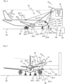
- FIG. 2 shows a schematic representation of a device 10 according to the invention for positioning an aircraft 22 shown in side view on an apron 24 of an airport.
- An FMCW LiDAR sensor 12 emits transmitted light beams 14.1, ..., 14.n into a three-dimensional monitoring area 16 in the apron 24 and generates measurement data M n 18 from transmitted light reflected or remitted from measuring points 20.1, ..., 20.n in the monitoring area 16 back to the FMCW LiDAR sensor 12.
- a limited number of exemplary transmitted light beams 14.1, ..., 14.n and measuring points 20.1, ..., 20.n are shown in the illustration; the actual number is determined by the size of the monitoring area 16 and the spatial resolution of the scanning.
- the measuring points 20.1, ..., 20.n can represent the aircraft 22 located in the monitoring area 16, but also people 26, vehicles (not shown), or the apron 24 itself.
- the measurement data M n 18 of the FMCW LiDAR sensor 12 received by a control and evaluation unit 32 include, for each time-discrete sampling, in addition to the radial distances r n and the intensities I n , i.e. the remitted or reflected amount of transmitted light, in particular the radial velocities v r n of the measuring points 20.1, ..., 20.n, where radial velocity v r n refers to the velocity component of a measuring point 20.1, ..., 20.n with which the measuring point 20.1, ..., 20.n moves towards or away from the FMCW LiDAR sensor 12.
- the control and evaluation unit 32 has at least one digital computing component, for example at least one microprocessor, at least one FPGA (Field Programmable Gate Array), at least one DSP (Digital Signal Processor), at least one ASIC (Application-Specific Integrated Circuit), at least one VPU (Video Processing Unit) or at least one neural processor.
- the control and evaluation unit 32 can also be provided at least partially externally of the FMCW LiDAR sensor 12, for example in a higher-level controller, a connected network, an edge device or a cloud.
- the measurement data M n 18 are evaluated by the control and evaluation unit 32, wherein the control and evaluation unit 32 is set up to segment the measurement points 20.1, ..., 20.n, to combine them at least partially into segments of the aircraft 22, such as the fuselage 22.2, the wheels 22.2 of the main landing gear, the engines 22.3, the cockpit window 22.4 or the aircraft nose 22.5, to extract features of the segments 22.1, ...., 22.n, to assign the segments 22.1, ...., 22.n to an aircraft type from a large number of aircraft types based on the extracted features and to output positioning information for the aircraft 22 via an interface 34 of the control and evaluation unit 32 based on the assigned aircraft type.
- an output unit 36 can be connected to the interface 34, which provides a pilot with the Positioning information, for example in the form of a distance to a type-specific parking position of the aircraft 22.
- the control and evaluation unit 32 can, for example, use the radial velocities v r n of the measuring points 20.1, ..., 20.n to determine movement patterns of the object segments 22.1, ..., 22.5, for example a rotation 26 of the wheels 22.2 of the main landing gear, and use the detected movement patterns to extract features of the segments 22.1, ..., 22.n.
- the control and evaluation unit 32 can further determine a velocity v 0 along a direction of movement 27 of the aircraft 22 using the radial velocities v r n of the measuring points 20.1, ..., 20.n, for example using a method as described in the scientific publication "Doppler velocity-based algorithm for Clustering and Velocity Estimation of moving objects (Guo et al., 2022)".
- FIG 3 shows a schematic representation of the device 10 according to the invention from Figure 2 , the aircraft 22 is shown in a frontal view. Identical parts are provided with identical reference numerals.
- the FMCW lidar sensor 12 is arranged on a passenger bridge 28.
- the control and evaluation unit can, for example, use the radial velocities v r n of measuring points that record the engine blades 30 of the engine 22.3 to determine a movement pattern of the engine blades 30, for example a rotation 32 of the engine blades 30. Since the engine blades have a very specific movement pattern due to their rotation, which differs significantly from movement patterns of other segments of the aircraft 22, the position of the engine blades 30 or the engine 22.3 can be detected particularly reliably.
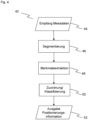
- Figure 4 shows in a flow chart 42 an exemplary inventive processing of the measurement data recorded by the FMCW LiDAR sensor 12 by the control and evaluation unit 32.
- the measurement points 20.1, ..., 20.n are segmented in a segmentation step 46 and combined into segments 22.1, ..., 22.5, of the aircraft 22, wherein in addition to the The spatial coordinates and intensities of the measuring points usually used for segmentation 46, in particular the spatially resolved radial velocities v r n of the measuring points 20.1, ..., 20.n can be taken into account.
- Segments of the aircraft can be, for example, the fuselage 22.2, the wheels 22.2 of the main landing gear, the engines 22.3, the cockpit window 22.4 or the aircraft nose 22.5.
- the segmentation 46 can be carried out, for example, according to the above-mentioned methods of digital image processing or machine vision or "range segmentation".
- the segmentation 46 of the measuring points 20.1, ..., 20.n can be carried out more efficiently and precisely using the methods listed above. For example, measuring points 20.1, ..., 20.n with radial velocities v r n smaller, greater or equal to a predetermined threshold value can be discarded and not subjected to any further evaluation.
- an object such as the aircraft 22 and/or object segment such as the aircraft nose 22.5 is scanned by several spatially discrete measuring points and the associated radial velocities can be distinguished, static and dynamic objects and/or object segments can be distinguished and thus stationary objects such as the apron 24 can be discarded before or during the segmentation 46 of the measuring points 20.1, ..., 20.n and the computational effort can be reduced by data reduction.
- the next step involves feature extraction 48 of the segments 22.1, ..., 22.5 defined during segmentation 46.
- Typical features that can be extracted from the segments 22.1, ..., 22.5 when processing the measurement data are, for example, width, number of measurement points or length of the circumference of the segments, or other features, such as those described in the scientific publication "A Layered Approach to People Detection in 3D Range Data" ( Spinello et al., Proceedings of the Twenty-Fourth AAAI Conference on Artificial Intelligence, AAAI 2010 ) are described.
- the segments 22.1, ..., 22.5 are assigned or classified 50 to an aircraft type from a large number of aircraft types using known classification methods such as Bayes classifiers, Support vector machines or artificial neural networks. As part of the assignment, the feature space is searched for groups of features that define a segment 22.1, ..., 22.5.
- an output 52 of positioning information for the aircraft 22 can be made based on the identified aircraft type.
- the positioning information can contain information on the distance and/or direction to an aircraft type-specific parking position for the aircraft 22 and can be shown on a display unit for a crew of the aircraft.
Landscapes
- Engineering & Computer Science (AREA)
- Physics & Mathematics (AREA)
- General Physics & Mathematics (AREA)
- Electromagnetism (AREA)
- Computer Networks & Wireless Communication (AREA)
- Radar, Positioning & Navigation (AREA)
- Remote Sensing (AREA)
- Aviation & Aerospace Engineering (AREA)
- Optical Radar Systems And Details Thereof (AREA)
Priority Applications (2)
| Application Number | Priority Date | Filing Date | Title |
|---|---|---|---|
| EP22200957.3A EP4354174B1 (fr) | 2022-10-11 | 2022-10-11 | Dispositif et procédé de positionnement d'un aéronef |
| US18/484,703 US20240369713A1 (en) | 2022-10-11 | 2023-10-11 | Device and method for positioning an aircraft |
Applications Claiming Priority (1)
| Application Number | Priority Date | Filing Date | Title |
|---|---|---|---|
| EP22200957.3A EP4354174B1 (fr) | 2022-10-11 | 2022-10-11 | Dispositif et procédé de positionnement d'un aéronef |
Publications (2)
| Publication Number | Publication Date |
|---|---|
| EP4354174A1 true EP4354174A1 (fr) | 2024-04-17 |
| EP4354174B1 EP4354174B1 (fr) | 2025-12-03 |
Family
ID=83690526
Family Applications (1)
| Application Number | Title | Priority Date | Filing Date |
|---|---|---|---|
| EP22200957.3A Active EP4354174B1 (fr) | 2022-10-11 | 2022-10-11 | Dispositif et procédé de positionnement d'un aéronef |
Country Status (2)
| Country | Link |
|---|---|
| US (1) | US20240369713A1 (fr) |
| EP (1) | EP4354174B1 (fr) |
Citations (8)
| Publication number | Priority date | Publication date | Assignee | Title |
|---|---|---|---|---|
| DE4301637C2 (de) | 1993-01-22 | 1997-05-22 | Daimler Benz Aerospace Ag | Verfahren zum Andocken eines Flugzeuges an eine Fluggastbrücke eines Flughafengebäudes |
| EP1015313B1 (fr) | 1997-09-22 | 2003-03-12 | Siemens Aktiengesellschaft | Dispositif d'accostage pour aerogares |
| US7702453B2 (en) | 2007-03-23 | 2010-04-20 | Dew Engineering And Development Ulc | System and method for guiding an aircraft to a stopping position |
| EP2109065B1 (fr) | 1999-10-29 | 2015-08-19 | Safegate International AB | Identification d'avion et système de guidage d'accueil |
| CN113721253A (zh) * | 2021-08-30 | 2021-11-30 | 杭州视光半导体科技有限公司 | 基于fmcw激光雷达的运动物体速度检测方法 |
| US20220066025A1 (en) * | 2019-01-11 | 2022-03-03 | Adb Safegate Sweden Ab | Airport stand arrangement |
| US20220137227A1 (en) * | 2020-11-02 | 2022-05-05 | Waymo Llc | Point cloud segmentation using a coherent lidar for autonomous vehicle applications |
| EP4030188A1 (fr) * | 2021-01-15 | 2022-07-20 | Sick Ag | Dispositif et procédé de sécurisation d'une zone de surveillance |
Family Cites Families (1)
| Publication number | Priority date | Publication date | Assignee | Title |
|---|---|---|---|---|
| DK3757968T3 (da) * | 2019-06-28 | 2022-04-19 | Adb Safegate Sweden Ab | Lufthavnsstandpladsarrangement og fremgangsmåde |
-
2022
- 2022-10-11 EP EP22200957.3A patent/EP4354174B1/fr active Active
-
2023
- 2023-10-11 US US18/484,703 patent/US20240369713A1/en active Pending
Patent Citations (8)
| Publication number | Priority date | Publication date | Assignee | Title |
|---|---|---|---|---|
| DE4301637C2 (de) | 1993-01-22 | 1997-05-22 | Daimler Benz Aerospace Ag | Verfahren zum Andocken eines Flugzeuges an eine Fluggastbrücke eines Flughafengebäudes |
| EP1015313B1 (fr) | 1997-09-22 | 2003-03-12 | Siemens Aktiengesellschaft | Dispositif d'accostage pour aerogares |
| EP2109065B1 (fr) | 1999-10-29 | 2015-08-19 | Safegate International AB | Identification d'avion et système de guidage d'accueil |
| US7702453B2 (en) | 2007-03-23 | 2010-04-20 | Dew Engineering And Development Ulc | System and method for guiding an aircraft to a stopping position |
| US20220066025A1 (en) * | 2019-01-11 | 2022-03-03 | Adb Safegate Sweden Ab | Airport stand arrangement |
| US20220137227A1 (en) * | 2020-11-02 | 2022-05-05 | Waymo Llc | Point cloud segmentation using a coherent lidar for autonomous vehicle applications |
| EP4030188A1 (fr) * | 2021-01-15 | 2022-07-20 | Sick Ag | Dispositif et procédé de sécurisation d'une zone de surveillance |
| CN113721253A (zh) * | 2021-08-30 | 2021-11-30 | 杭州视光半导体科技有限公司 | 基于fmcw激光雷达的运动物体速度检测方法 |
Non-Patent Citations (10)
| Title |
|---|
| BEHLEY ET AL.: "Laser-based segment classification using a mixture of bag-of-words", IEEE/RSJ INTERNATIONAL CONFERENCE ON INTELLIGENT ROBOTS AND SYSTEMS, DOI: 10.1109/I ROS.2013.6696957, 2013 |
| BOGOSLAVSKYI ET AL.: "Fast Range Image-Based Segmentation of Sparse 3D Laser Scans for Online Operation", IEEE/RSJ INTERNATIONAL CONFERENCE ON INTELLIGENT ROBOTS AND SYSTEMS, DOI: 10.1109/IROS.2016.7759050, 2016 |
| DOUILLARD ET AL.: "On the segmentation of 3d lidar point clouds", IEEE INTERNATIONAL CONFERENCE ON ROBOTICS AND AUTOMATION, 2011 |
| GUO ET AL., DOPPLER VELOCITY-BASED ALGORITHM FOR CLUSTERING AND VELOCITY ESTIMATION OF MOVING OBJECTS, 2022 |
| GUO, YULAN ET AL.: "Deep learning for 3d point clouds: A survey", IEEE TRANSACTIONS ON PATTERN ANALYSIS AND MACHINE INTELLIGENCE, vol. 43, no. 12, 2020, pages 4338 - 4364, XP011886434, DOI: 10.1109/TPAMI.2020.3005434 |
| LANG, ALEX H. ET AL.: "Pointpillars: Fast encoders for object detection from point clouds", PROCEEDINGS OF THE IEEE/CVF CONFERENCE ON COMPUTER VISION AND PATTERN RECOGNITION, 2019 |
| PIERROTTET, D.AMZAJERDIAN, F.PETWAY, L.BARNES, B.LOCKARD, G.RUBIO, M.: "Linear FMCW Laser Radar for Precision Range and Vector Velocity Measurements", MRS PROCEEDINGS, vol. 1076, 2008 |
| SPINELLO ET AL.: "A Layered Approach to People Detection in 3D Range Data", PROCEEDINGS OFTHE TWENTY-FOURTH AAAI CONFERENCE ON ARTIFICIAL INTELLIGENCE, 2010 |
| T. KIM: "Realization of Integrated Coherent LiDAR", 2019, UNIVERSITY OF CALIFORNIA |
| YAN, YANYUXING MAOBO LI: "Second: Sparsely embedded convolutional detection", SENSORS, vol. 18, no. 10, 2018, pages 3337, XP055866583, DOI: 10.3390/s18103337 |
Also Published As
| Publication number | Publication date |
|---|---|
| EP4354174B1 (fr) | 2025-12-03 |
| US20240369713A1 (en) | 2024-11-07 |
Similar Documents
| Publication | Publication Date | Title |
|---|---|---|
| DE19531632B4 (de) | Entfernungsmeßgerät | |
| DE102021100351A1 (de) | Adaptive untersuchung für lidar-basiertes gruppieren | |
| EP4030188B1 (fr) | Dispositif et procédé de sécurisation d'une zone de surveillance | |
| DE102020203796B4 (de) | Verfahren und Vorrichtung zum Bestimmen einer Messinformation und LiDAR-Gerät | |
| EP1788467B1 (fr) | Dispositif de protection | |
| EP4139709B1 (fr) | Procédé et dispositif d'identification de l'efflorescence dans une mesure lidar | |
| DE102017217844A1 (de) | Verfahren und ein maschinelles Lernsystem zur Klassierung von Objekten | |
| EP3663881B1 (fr) | Procédé de commande d'un véhicule autonome en fonction des vecteurs de mouvement estimés | |
| EP3885787B1 (fr) | Acquisition de données de mesure de distance | |
| EP4354174B1 (fr) | Dispositif et procédé de positionnement d'un aéronef | |
| EP4310548A2 (fr) | Dispositif et procédé de surveillance d'une chaussée | |
| EP2977786B1 (fr) | Capteur telemetrique destine a la detection et la determination de l'eloignement d'objets | |
| DE202022105739U1 (de) | Vorrichtung zur Positionierung eines Flugzeuges | |
| EP3715908B1 (fr) | Procédé et dispositif de mesure optique de distance | |
| EP3663800B1 (fr) | Procédé de détection d'objet à l'aide d'une camera tridimensionnelle | |
| WO2024099918A1 (fr) | Capteur lidar, en particulier pour véhicule à conduite automatisée | |
| EP4310541A1 (fr) | Dispositif et procédé de détection d'objets dans une zone de surveillance | |
| DE202014103348U1 (de) | Entfernungsmessender Sensor zur Erfassung und Abstandsbestimmung von Objekten | |
| DE102014223741A1 (de) | Erfassen von Terahertz-Strahlung zum Unterstützen eines Fahrers eines Fahrzeugs | |
| DE202022104108U1 (de) | Vorrichtung zur Erfassung von Objekten in einem Überwachungsbereich | |
| WO2024002437A1 (fr) | Procédé et système de surveillance de l'état de la route au moyen d'un système d'apprentissage machine, et procédé d'entraînement du système d'apprentissage machine | |
| DE202022104107U1 (de) | Vorrichtung zur Erfassung von Objekten | |
| DE202021100171U1 (de) | Vorrichtung zum Absichern eines Überwachungsbereiches | |
| DE102023117171A1 (de) | Verfahren zum korrigieren von bewegungsunschärfe und lidar-system | |
| DE102025113762A1 (de) | Verfahren, Steueranordnung und Fahrzeug zur Erfassung falscher positiverErgebnisse bei LiDAR-Messungen |
Legal Events
| Date | Code | Title | Description |
|---|---|---|---|
| PUAI | Public reference made under article 153(3) epc to a published international application that has entered the european phase |
Free format text: ORIGINAL CODE: 0009012 |
|
| STAA | Information on the status of an ep patent application or granted ep patent |
Free format text: STATUS: THE APPLICATION HAS BEEN PUBLISHED |
|
| AK | Designated contracting states |
Kind code of ref document: A1 Designated state(s): AL AT BE BG CH CY CZ DE DK EE ES FI FR GB GR HR HU IE IS IT LI LT LU LV MC ME MK MT NL NO PL PT RO RS SE SI SK SM TR |
|
| STAA | Information on the status of an ep patent application or granted ep patent |
Free format text: STATUS: REQUEST FOR EXAMINATION WAS MADE |
|
| 17P | Request for examination filed |
Effective date: 20241014 |
|
| RBV | Designated contracting states (corrected) |
Designated state(s): AL AT BE BG CH CY CZ DE DK EE ES FI FR GB GR HR HU IE IS IT LI LT LU LV MC ME MK MT NL NO PL PT RO RS SE SI SK SM TR |
|
| STAA | Information on the status of an ep patent application or granted ep patent |
Free format text: STATUS: EXAMINATION IS IN PROGRESS |
|
| 17Q | First examination report despatched |
Effective date: 20241211 |
|
| GRAP | Despatch of communication of intention to grant a patent |
Free format text: ORIGINAL CODE: EPIDOSNIGR1 |
|
| STAA | Information on the status of an ep patent application or granted ep patent |
Free format text: STATUS: GRANT OF PATENT IS INTENDED |
|
| INTG | Intention to grant announced |
Effective date: 20250701 |
|
| GRAS | Grant fee paid |
Free format text: ORIGINAL CODE: EPIDOSNIGR3 |
|
| GRAA | (expected) grant |
Free format text: ORIGINAL CODE: 0009210 |
|
| STAA | Information on the status of an ep patent application or granted ep patent |
Free format text: STATUS: THE PATENT HAS BEEN GRANTED |
|
| AK | Designated contracting states |
Kind code of ref document: B1 Designated state(s): AL AT BE BG CH CY CZ DE DK EE ES FI FR GB GR HR HU IE IS IT LI LT LU LV MC ME MK MT NL NO PL PT RO RS SE SI SK SM TR |
|
| REG | Reference to a national code |
Ref country code: CH Ref legal event code: F10 Free format text: ST27 STATUS EVENT CODE: U-0-0-F10-F00 (AS PROVIDED BY THE NATIONAL OFFICE) Effective date: 20251203 Ref country code: GB Ref legal event code: FG4D Free format text: NOT ENGLISH |
|
| REG | Reference to a national code |
Ref country code: DE Ref legal event code: R096 Ref document number: 502022006289 Country of ref document: DE |
|
| REG | Reference to a national code |
Ref country code: IE Ref legal event code: FG4D Free format text: LANGUAGE OF EP DOCUMENT: GERMAN |