EP4354204A1 - Système optique, et dispositif d'affichage d'image - Google Patents
Système optique, et dispositif d'affichage d'image Download PDFInfo
- Publication number
- EP4354204A1 EP4354204A1 EP22819943.6A EP22819943A EP4354204A1 EP 4354204 A1 EP4354204 A1 EP 4354204A1 EP 22819943 A EP22819943 A EP 22819943A EP 4354204 A1 EP4354204 A1 EP 4354204A1
- Authority
- EP
- European Patent Office
- Prior art keywords
- branch
- region
- optical system
- directions
- exit
- Prior art date
- Legal status (The legal status is an assumption and is not a legal conclusion. Google has not performed a legal analysis and makes no representation as to the accuracy of the status listed.)
- Pending
Links
Images



Classifications
-
- G—PHYSICS
- G02—OPTICS
- G02B—OPTICAL ELEMENTS, SYSTEMS OR APPARATUS
- G02B27/00—Optical systems or apparatus not provided for by any of the groups G02B1/00 - G02B26/00, G02B30/00
- G02B27/0081—Optical systems or apparatus not provided for by any of the groups G02B1/00 - G02B26/00, G02B30/00 with means for altering, e.g. enlarging, the entrance or exit pupil
-
- G—PHYSICS
- G02—OPTICS
- G02B—OPTICAL ELEMENTS, SYSTEMS OR APPARATUS
- G02B27/00—Optical systems or apparatus not provided for by any of the groups G02B1/00 - G02B26/00, G02B30/00
- G02B27/01—Head-up displays
- G02B27/017—Head mounted
- G02B27/0172—Head mounted characterised by optical features
-
- G—PHYSICS
- G02—OPTICS
- G02B—OPTICAL ELEMENTS, SYSTEMS OR APPARATUS
- G02B5/00—Optical elements other than lenses
- G02B5/18—Diffraction gratings
- G02B5/1809—Diffraction gratings with pitch less than or comparable to the wavelength
-
- G—PHYSICS
- G02—OPTICS
- G02B—OPTICAL ELEMENTS, SYSTEMS OR APPARATUS
- G02B5/00—Optical elements other than lenses
- G02B5/18—Diffraction gratings
- G02B5/1866—Transmission gratings characterised by their structure, e.g. step profile, contours of substrate or grooves, pitch variations, materials
-
- G—PHYSICS
- G02—OPTICS
- G02B—OPTICAL ELEMENTS, SYSTEMS OR APPARATUS
- G02B6/00—Light guides; Structural details of arrangements comprising light guides and other optical elements, e.g. couplings
- G02B6/24—Coupling light guides
- G02B6/26—Optical coupling means
- G02B6/34—Optical coupling means utilising prism or grating
-
- G—PHYSICS
- G02—OPTICS
- G02B—OPTICAL ELEMENTS, SYSTEMS OR APPARATUS
- G02B27/00—Optical systems or apparatus not provided for by any of the groups G02B1/00 - G02B26/00, G02B30/00
- G02B27/01—Head-up displays
- G02B27/017—Head mounted
- G02B27/0172—Head mounted characterised by optical features
- G02B2027/0174—Head mounted characterised by optical features holographic
Definitions
- the present disclosure relates to optical systems and image display devices.
- Patent Literature 1 discloses an optical element (optical system) including a waveguide (light guide) for expanding an exit pupil in two directions.
- the optical element includes three diffractive optical elements (DOEs).
- the first DOE is configured to couple a beam from an imager into the waveguide.
- the second DOE expands the exit pupil in a first direction along a first coordinate axis.
- the third DOE expands the exit pupil in a second direction along a second coordinate axis and couples light out of the waveguide.
- Patent Literature 2 discloses a waveguide including a surface provided with an in-coupling diffractive optic and an out-coupling diffractive optic.
- the out-coupling diffractive optic includes a diffractive array having rows with different grating vectors are arranged alternately and therefore has multiple grating vectors which are not parallel to the grating vector of the in-coupling diffractive optic.
- Patent Literatures 1 and 2 are used for head mounted displays, for example.
- head mounted displays depending on how to use the optical element, there may be a demand for downsizing the waveguide of the optical element.
- the present disclosure provides an optical system and an image display device capable of downsizing a light guide.
- An optical system includes: a light guide for guiding an image light ray which is output from a display element and forms an image, to a field of view region of a user as a virtual image, the light guide including a body having a plate shape and a periodic structure formed in the body, the periodic structure having periodicity in three predetermined directions intersecting each other within a predetermined plane perpendicular to a thickness direction of the body, and the periodic structure including an in-coupling region dividing the image light ray incident from the display element into a plurality of the image light rays and allowing the plurality of image light rays to propagate within the body in a plurality of branch directions including first, second, and third branch directions respectively parallel to the three predetermined directions, and an exit region allowing the plurality of image light rays propagating in the plurality of branch directions within the body to emerge from the body toward the field of view region.
- An image display device includes the above optical system and the display element.
- aspects of the present disclosure enables downsizing a light guide.
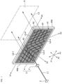
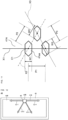
- Fig. 1 is a schematic view of a configuration example of an image display device 1 according to one embodiment.
- the image display device 1 is, for example, a head mounted display (HMD) which is mounted on a user's head and displays an image (picture).
- a "direction of_ axis" means a direction which passes an arbitrary point and is parallel to the _ axis.
- expressions "travel in _ direction” and “propagate in _ direction” used in relation to light rays mean that a light ray forming an image travels in the _ direction as a whole and therefore light beams included in the light ray forming the image may be permitted to be inclined relative to the _direction.
- a "light ray traveling in _ direction” it is sufficient that a main light beam of this light is directed in the _ direction, and auxiliary beams of this light may be inclined relative to the _ direction.
- the image display device 1 includes a display element 2 and an optical system 3.
- the display element 2 is configured to output an image light ray L1 forming an image.
- the optical system 3 includes a light guide 4 and a projection optical system 5.
- the light guide 4 guides the image light ray L1 output from the display element 2 to a field of view region 6 of a user as a virtual image.
- the light guide 4 includes a body 40 having a plate shape and a periodic structure formed in the body 40.
- the image light ray L1 is depicted as light with directivity. However, actually, the image light ray L1 is incident on the light guide 4 as light having an angle corresponding to a field of view.
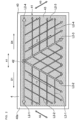
- Fig. 2 is a schematic plan view of a configuration example of the light guide 4
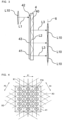
- Fig. 3 is a schematic side view of the configuration example of the light guide 4.
- a pupil L10 is depicted instead of the display element 2 and the projection optical system 5.
- the periodic structure 41 of the light guide 4 has periodicity in three predetermined directions A1, A2, A3 intersecting each other within a predetermined plane perpendicular to the thickness direction of the body 40.
- the periodic structure 41 includes an in-coupling region 42 and an exit region 43.
- the in-coupling region 42 divides the image light ray L1 into a plurality of the image light rays and allowing the plurality of image light rays to propagate within the body 40 in a plurality of branch directions D1 to D4 including first, second, and third branch directions D1, D2, and D3 respectively parallel to the three predetermined directions A1, A2, A3, as shown in Fig. 2 .
- the exit region 43 allows the plurality of image light rays L2-1 to L2-4 (hereinafter, collectively designated by reference sign L2) propagating within the body 40 in the plurality of branch directions D1 to D4 to emerge from the body 40 toward the field of view region 6.
- the in-coupling region 42 divides the image light ray L1 into a plurality of the image light rays and allowing the plurality of image light rays to propagate inside the body 40 in the plurality of branch directions D1 to D4 including the first, second, and third branch directions D1, D2, and D3 respectively parallel to the three predetermined directions A1, A2, A3, and the exit region 43 allows the plurality of image light rays L2-1 to L2-4 propagating within the body 40 in the plurality of branch directions D1 to D4 to emerge from the body 40 toward the field of view region 6.
- the light guide 4 reproduces a pupil of the image right ray L1 to expand the pupil by: dividing the image light ray L1 into a plurality of the image light rays in the plurality of branch directions D1 to D4; further dividing the plurality of image light rays into a plurality of the image light rays L3 parallel to each other; and allowing the plurality of image light rays L3 to emerge toward the field of view region 6.
- the periodic structure 41 functions as the in-coupling region 42 and the exit region 43 and therefore enables expansion of the pupil by the periodic structure 41 only. Therefore, there is no need to employ two or three diffraction optical elements, differently from Patent Literatures 1 and 2. This lead to downsizing the light guide 4.
- the image display device 1 includes the display element 2 and the optical system 3.
- the display element 2 is configured to, in order to display an image (picture), output the image light ray L1 for forming the image.
- the image light ray L1 includes light beams output from respective points of the display element 2.
- the respective points of the display element 2 correspond to respective pixels of the display element 2, for example.
- the optical axis of the image light ray L1 is an optical axis of a light ray output from a center of the display element 2, for example.
- Examples of the display element 2 may include known displays such as liquid crystal displays, organic EL displays, scanning MEMS mirrors, or the like.
- the optical system 3 is configured to guide the image light ray L1 output from the display element 2 toward the field of view region 6 set relative to eyes of the user.
- the user can watch by his or her own eyes the image formed by the display element 2 with the image not being interrupted.
- the optical system 3 expands the field of view region 6 by utilizing effects of pupil expansion.
- the optical system 3 includes the light guide 4 and the projection optical system 5.
- the light guide 4 is configured to guide the image light ray L1 which is output from the display element 2 and forms the image, toward the field of view region 6 as a virtual image.
- the light guide 4 includes the body 40 having a plate shape and the periodic structure 41.
- the body 40 is made of transparent material and includes a first surface 40a and a second surface 40b in a thickness direction thereof.
- the body 40 has a rectangular plate shape. As shown in Fig. 1 , the body 40 is positioned or arranged to direct the first surface 40a toward the display element 2 and direct the second surface 40b toward the field of view region 6.
- the periodic structure 41 is formed in the first surface 40a of the body 40.
- the periodic structure 41 is a rectangular region formed in the first surface 40a of the body 40, for example.
- the periodic structure 41 has periodicity in three predetermined directions A1, A2, A3 intersecting each other within a predetermined plane perpendicular to the thickness direction of the body 40.
- the three predetermined directions A1, A2, A3 are not perpendicular to each other.
- Periods of the periodic structure 41 in the individual three predetermined directions A1, A2, A3 are constant and identical to each other.
- the predetermined direction A1 corresponds to a length direction of the body 40. Based on a counterclockwise direction in Fig.
- the predetermined direction A2 intersects the predetermined direction A1 at a predetermined angle (e.g., 60 degrees) and the predetermined direction A3 intersects the predetermined direction A1 at a different predetermined angle (e.g., 120 degrees).
- a predetermined angle e.g. 60 degrees
- a different predetermined angle e.g. 120 degrees
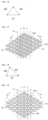
- Fig. 4 is a plan view of a configuration example of the periodic structure 41 and Fig. 5 is a perspective view of the configuration example of the periodic structure 41.
- the periodic structure 41 includes a diffraction grating constituted by recessed or protruded parts 41a in relation to the thickness direction of the body 40 which are arranged within the predetermined plane to have periodicity in the three predetermined directions A1, A2, A3.
- the recessed or protruded parts 41a are arranged to satisfy following conditions (1) to (3).
- the condition (1) specifies that in the predetermined direction A1, rows of the recessed or protruded parts 41a arranged in a direction X1 perpendicular to the predetermined direction A1 are arranged at a regular interval. Satisfying the condition (1) allows the periodic structure 41 to function as a diffraction grating for diffracting light into the predetermined direction A1.
- the condition (2) specifies that in the predetermined direction A2, rows of the recessed or protruded parts 41a arranged in a direction X2 perpendicular to the predetermined direction A2 are arranged at a regular interval. Satisfying the condition (2) allows the periodic structure 41 to function as a diffraction grating for diffracting light into the predetermined direction A2.
- the condition (3) specifies that in the predetermined direction A3, rows of the recessed or protruded parts 41a arranged in a direction X3 perpendicular to the predetermined direction A3 are arranged at a regular interval. Satisfying the condition (3) allows the periodic structure 41 to function as a diffraction grating for diffracting light into the predetermined direction A3.
- the recessed or protruded parts 41a are arranged in a hexagonal lattice, thereby satisfying the conditions (1) to (3).
- each recessed or protruded part 41a is a protrusion with a hexagonal shape in its plan view.
- the periodic structure 41 includes the in-coupling region 42 and the exit region 43.
- the periodic structure 41 is formed not to include a region separating the in-coupling region 42 and the exit region 43 between the in-coupling region 42 and the exit region 43.
- the region separating the in-coupling region 42 and the exit region 43 may include a region where no recessed or protruded part 41a is present, or a region where recessed or protruded structure different from the recessed or protruded parts 41a is present.
- the periodic structure 41 is formed so that the in-coupling region 42 and the exit region 43 are not discontinuous but consecutive smoothly. This enables simplification of the structure of the periodic structure 41.
- the in-coupling region 42 is a region on which the image light ray L1 from the display element 2 is incident, in the periodic structure 41. Therefore, the in-coupling region 42 is defined by a group of recessed or protruded parts 41a which is of the recessed or protruded parts 41a arranged within the predetermined plane to have periodicity in the three predetermined directions A1, A2, A3 and is within a region on which the image light ray L1 from the display element 2 is incident.
- the in-coupling region 42 is used for coupling between the display element 2 and the light guide 4.
- the in-coupling region 41 allows external light ray (the image light ray L1) to be incident on the light guide 4 and propagate within the body 40 of the light guide 4 under a total reflection condition (see Fig. 3 ).
- the term "coupling” used herein means allowing propagation inside the body 40 of the light guide 4 under a total reflection condition.
- the in-coupling region 42 is a partial region of the periodic structure 41 and thus has periodicity in the three predetermined directions A1, A2, A3. Accordingly, the in-coupling region 42 divides the image light ray L1 incident from the display element 2 into a plurality of the image light rays and allows the plurality of image light rays to propagate within the body 40 in a plurality of branch directions.
- the in-coupling region 42 is located at one end in a width direction of the periodic structure 41 and at a center in a length direction of the periodic structure 41.
- the plurality of branch directions include first, second and third branch directions D1, D2, D3 respectively parallel to the three predetermined directions A1, A2, A3.
- the plurality of branch directions further include a fourth branch direction D4.
- the fourth branch direction D4 is an opposite direction from the first branch direction D1.
- An angle between the first branch direction D1 and the fourth branch direction D4 is larger than the angle between the first branch direction D1 and the third branch direction D3.
- the angle between the first branch direction D1 and the second branch direction D2 is 60 degrees
- the angle between the first branch direction D1 and the third branch direction D3 is 120 degrees
- the angle between the first branch direction D1 and the fourth branch direction D4 is 180 degrees.
- the angles herein are defined so that a counterclockwise direction when the light guide 4 is viewed in a direction where the image light ray L1 is incident on the light guide 4 is a positive direction.
- the in-coupling region 42 uses diffraction to allow the image light ray L1 to be incident on the body 40 of the light guide 4 to meet a condition where it is totally reflected by the first surface 40a and the second surface 40b.
- the in-coupling region 42 allows the image light ray L1 to travel in a direction of the first axis (the X axis in the present embodiment) within the light guide 4 (i.e., the body 40) while being totally reflected by the first surface 40a and the second surface 40b.
- the in-coupling region 42 is arranged side by side with the exit region 43 in each of the three predetermined directions A1, A2, A3. Consequently, an entire image light ray L2 from the in-coupling region 42 is incident on the exit region 43 and this can improve a transfer efficiency from the in-coupling region 42 to the exit region 43.
- the in-coupling region 42 allows the image light ray L1 to travel in each of the plurality of branch directions D1 to D4 within the body 40 of the light guide 4 while being totally reflected by the first surface 40a and the second surface 40b.
- the in-coupling region 42 allows image light rays L2-1 to L2-4 propagating within the body in the plurality of branch directions D1 to D4 respectively to branch off from the image light ray L1.
- the in-coupling region 42 divides the image light ray L1 into the image light rays L2-1 to L2-4 propagating within the body in the plurality of branch directions D1 to D4 respectively.
- the exit region 43 is a region which allows image light rays L3 to emerge toward the field of view region 6, in the periodic structure 41.
- the exit region 43 is a region of the periodic structure 41 other than the in-coupling region 42.
- the exit region 43 is defined by a group of recessed or protruded parts 41a which is of the recessed or protruded parts 41a arranged within the predetermined plane to have periodicity in the three predetermined directions A1, A2, A3 but is not included in the in-coupling region 42.
- the exit region 43 allows the image light rays L2-1 to L2-4 propagating within the body 40 in the plurality of branch directions D1 to D4, to emerge from the body 40 toward the field of view region 6.
- the exit region 43 allows each image light ray L2 from the in-coupling region 42 to propagate in its branch direction and allows part of each image light ray L2 to emerge from the light guide 4 toward the field of view region 6.
- the exit region 43 is a partial region of the periodic structure 41 and thus has periodicity in the three predetermined directions A1, A2, A3. Accordingly, the exit region 43 allows part of the image light ray L2 to travel in a different branch direction from its original branch direction.
- Fig. 2 illustrates an example situation where a plurality of image light rays L2-2 traveling in the second branch direction D2 branch off from the image light rays L2-1 traveling from the in-coupling region 42 in the first branch direction D1.
- Fig. 2 illustrates an example situation where a plurality of image light rays L2-1, L2-3 traveling in the first and third branch directions D1, D3 branch off from the image light ray L2-2 traveling from the in-coupling region 42 in the second branch direction D2.
- FIG. 2 illustrates an example situation where a plurality of image light rays L2-2, L2-4 traveling in the second and fourth branch directions D2, D4 branch off from the image light ray L2-3 traveling from the in-coupling region 42 in the third branch direction D3.
- Fig. 2 illustrates an example situation where a plurality of image light rays L2-3 traveling in the third branch direction D3 branch off from the image light ray L2-4 traveling from the in-coupling region 42 in the fourth branch direction D4.
- the image light ray L1 is divided within the body 40 into the plurality of image light rays L2-1 to L2-4 traveling respectively in the plurality of branch directions D1 to D4 and thus spreads within the predetermined plane perpendicular to the thickness direction of the body 40.
- Each of the plurality of image light rays L2-1 to L2-4 traveling respectively in the plurality of branch directions D1 to D4 is divided into a plurality of mutually parallel image light rays L3 (see Fig. 3 ) and thereby emerges from the body 40 toward the field of view region 6.
- Each of the in-coupling region 42 and the exit region 43 is a partial region of the periodic structure 41 and thus has periodicity in the three predetermined directions A1, A2, A3. Therefore, the in-coupling region 42 and the exit region 43 have the same periods in the three predetermined directions A1, A2, A3, individually. This enables simplification of the structure of the periodic structure 41.
- individual wave vectors in the plurality of branch directions of the periodic structure 41 are set as follows.
- the individual wave vectors in the first, second, third and fourth branch directions D1, D2, D3, D4 of the periodic structure 41 are denoted by k1, k2, k3, k4.
- an n-th (n is integer equal to or greater than 3) branch direction is set so that an angle between the first branch direction and the n-th branch direction is larger than an angle between the first branch direction and an (n-1)th branch direction.
- the angles herein are defined so that a counterclockwise direction when the light guide 4 is viewed in a direction where the image light ray L1 is incident on the light guide 4 is a positive direction.
- components of the wave vector are set based on an x-y plane defined by an x axis a direction of which is specified by the predetermined direction A1 and a y axis specified by a direction perpendicular to the predetermined direction A1 within the predetermined plane.
- a center of the in-coupling region 42 may be selected as an origin of the x-y plane.
- the wave vectors in the first, second, and third branch directions D1, D2, D3 of the periodic structure 41 are denoted by k1, k2, k3, respectively, and a maximum value of absolute values of the wave vectors k1, k2, k3 in the first, second, and third branch directions D1, D2, D3 is denoted by km
- the wave vectors k1, k2, k3 satisfy a relation of
- the wave vectors k1, k2, k3 satisfy
- the wave vectors k1, k2, k3 satisfy
- 0.
- an angle of the image light ray L1 incident on the in-coupling region 42 is identical to an angle of the image light ray L3 emerging from the exit region 43 toward the field of view region 6. It is possible to keep the angle of the image light ray L1 unchanged. This enables further improvement of image quality.
- the wave vectors k1, k2, k3 satisfy a relation of
- 0.
- 0 should not be interpreted in strict sense but may permit that k1-k2+k3 is regarded as 0.
- the wave vectors k2, k3, k4 satisfy a relation of
- 0.
- is an absolute value of a resultant vector represented by k4+k2-k3.
- the wave vectors k1, k4 satisfy a relation of
- 0.
- is an absolute value of a resultant vector represented by k1+k4.
- the individual absolute values of the wave vectors k1, k2, k3, and k4 are identical to each other.
- the image light ray L1 is incident on the in-coupling region 42 along the thickness direction of the body 40, it is possible to arrange the pupils L10 of the image light ray L1 at a regular interval in the field of view region 6.
- the pupils L10 of the image light ray L1 is incident on the in-coupling region 42 along the thickness direction of the body 40, it is possible to arrange the pupils L10 of the image light ray L1 to reduce an area of the field of view region 6 where no pupil L10 is located.
- the aforementioned light guide 4 reproduces the pupil L10 of the image right ray L1 to expand the pupil L10 by: dividing the image light ray L1 entering the body 40 from the in-coupling region 42 within the body 40 into the plurality of image light rays L2 propagating in the plurality of branch direction; and further dividing the plurality of image light rays L2 propagating in the plurality of branch directions into a plurality of mutually parallel image light rays L3 to allow them to emerge toward the field of view region 6.
- the projection optical system 5 projects the image light ray L1 which is output from the display element 2 and forms the image.
- the projection optical system 5 allows the image light ray L1 from the display element 2 to be incident on the light guide 4.
- the projection optical system 5 is located between the display element 2 and the in-coupling region 42 of the light guide 4.
- the projection optical system 5 collimates the image light ray L1 from the display element 2 and allows it to be incident on the in-coupling region 42, for example.
- the projection optical system 5 allows the image light ray L1 to be incident on the in-coupling region 42 as substantial collimate light ray.
- the projection optical system 5 is, for example, a biconvex lens.
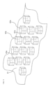
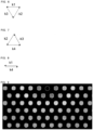
- Fig. 9 shows a result of the simulation regarding light intensities of the light guide 4.
- Fig. 9 shows a distribution of light intensity at each of plurality of parts set on the exit region 43 of the light guide 4 at a predetermined interval.
- part indicated by a white dashed circle corresponds to the in-coupling region 42.
- a size of the pupil L10 of the image light ray L1 is set to prevent reproduced pupils from overlapping with each other. As apparent from Fig. 9 , light is distributed over the entire exit region 43.
- the pupil L10 of the image light ray L1 could be reproduced and expanded by the periodic structure 41 which has periodicity in the three predetermined directions A1, A2, A3 intersecting each other within the predetermined plane perpendicular to the thickness direction of the body 40.
- the optical system 3 includes the light guide 4 for guiding the image light ray L1 which is output from the display element 2 and forms the image, to the field of view region 6 of the user as the virtual image.
- the light guide 4 includes the body 40 having a plate shape and the periodic structure 41 formed in the body 40.
- the periodic structure 41 has periodicity in the three predetermined directions A1, A2, A3 intersecting each other within the predetermined plane perpendicular to the thickness direction of the body 40.
- the periodic structure 41 includes the in-coupling region 42 dividing the image light ray L1 incident from the display element 2 into a plurality of the image light rays L2 and allowing the plurality of image light rays to propagate within the body 40 in the plurality of branch directions including the first, second, and third branch directions D1, D2, D3 respectively parallel to the three predetermined directions A1, A2, A3, and the exit region 43 allowing the plurality of image light rays L2 propagating in the plurality of branch directions within the body 40 to emerge from the body 40 toward the field of view region 6.
- This configuration enables downsizing the light guide 4.
- the periodic structure 41 includes a diffraction grating constituted by the recessed or protruded parts 41a in relation to the thickness direction of the body 40 which are arranged within the predetermined plane to have periodicity. This configuration enables simplification of the structure of the light guide 4.
- the recessed or protruded parts 41a are arranged within the predetermined plane in a hexagonal lattice. This configuration enables downsizing the light guide 4.
- the in-coupling region 42 and the exit region 43 have the same period in each of the three predetermined directions A1, A2, A3. That is, a period in the predetermined directions A1, of the in-coupling region 42 is identical to a period in the predetermined directions A1, of the exit region 43; a period in the predetermined directions A2, of the in-coupling region 42 is identical to a period in the predetermined directions A2, of the exit region 43; and a period in the predetermined directions A3, of the in-coupling region 42 is identical to a period in the predetermined directions A3, of the exit region 43.
- the periods in the predetermined directions A1, A2, A3, of the in-coupling region 42 are not necessarily identical to each other and the periods in the predetermined directions A1, A2, A3, of the exit region 43 are not necessarily identical to each other.
- This configuration enables simplification of the structure of the light guide 4.
- the wave vectors in the first, second, and third branch directions D1, D2, D3 of the periodic structure 41 are denoted by k1, k2, and k3, respectively, and a maximum value of absolute values of the wave vectors in the first, second, and third branch directions D1, D2, D3 is denoted by km
- the wave vectors k1, k2, and k3 satisfy a relation of
- the wave vectorsk1, k2, and k3 satisfy a relation of
- 0. This configuration enables improvement of image quality.
- the absolute values of the wave vectors k1, k2, and k3 are identical to each other. This configuration enables arranging the pupils L10 of the image light ray L1 at a regular interval in the field of view region 6.
- the light guide 4 reproduces the pupil L10 of the image right ray L1 to expand the pupil L10 by: converting the image light ray L1 entering the light guide 4 from the in-coupling region 42 into a plurality of image light rays in the plurality of branch directions allowed to propagate in the plurality of branch directions within the body 40; and dividing the plurality of image light rays into a plurality of mutually parallel image light rays L3 in each of the plurality of branch directions to be allowed to emerge toward the field of view region 6.
- This configuration enables downsizing the light guide 4.
- the in-coupling region 42 is arranged side by side with the exit region 43 in each of the three predetermined directions A1, A2, A3. This configuration enables improvement of the transfer efficiency of light from the in-coupling region 42 to the exit region 43.
- the periodic structure 41 is formed not to include a region separating the in-coupling region 42 and the exit region 43 between the in-coupling region 42 and the exit region 43. This configuration enables simplification of the structure of the periodic structure 41.
- the optical system 3 further includes the projection optical system 5 allowing the image light ray L1 to be incident on the in-coupling region 42 of the light guide 4 as a substantial collimate light ray. This configuration enables improvement of a use efficiency of the image light ray L1.
- the aforementioned image display device 1 includes the aforementioned optical system 3 and the display element 2. This configuration enables downsizing the light guide 4.
- Embodiments of the present disclosure are not limited to the above embodiment.
- the above embodiment may be modified in various ways in accordance with designs or the like to an extent that they can achieve the problem of the present disclosure.
- some variations or modifications of the above embodiment will be listed.
- One or more of the variations or modifications described below may apply in combination with one or more of the others.
- Fig. 10 is a schematic view of a configuration example of a light guide 4A of variation 1.
- the light guide 4A includes the body 40 and a periodic structure 41A.
- the periodic structure 41A has periodicity in the three predetermined directions A1, A2, A3 intersecting each other within the predetermined plane perpendicular to the thickness direction of the body 40.
- the periodic structure 41A includes a diffraction grating constituted by recessed or protruded parts 41aa in relation to the thickness direction of the body 40 which are arranged within the predetermined plane to have periodicity in the three predetermined directions A1, A2, A3.
- shapes of the recessed or protruded parts 41aa of the periodic structure 41A are different depending on a position inside the periodic structure 41A.
- the periodic structure 41A includes regions with different diffraction efficiencies for light rays under the same condition.
- the light rays under the same condition are light rays which are the same in at least a wavelength and an incident angle, for example.
- the periodic structure 41A will be described in more detail.
- the periodic structure 41A of Fig. 10 includes the in-coupling region 42 and an exit region 43A.
- each recessed or protruded part 41aa is a protrusion with a hexagonal shape in its plan view. Therefore, the in-coupling region 42 divides the image light ray L1 into the image light rays L2-1 to L2-4 propagating within the body 40 in the plurality of branch directions D1 to D4.
- the in-coupling region 42A diffracts the image light ray L1 in the first, second, third, and fourth branch directions D1, D2, D3, D4.
- the exit region 43A includes a plurality of (four, in the illustrated example) exit parts 44-1 to 44-4 (hereinafter, collectively designated by the reference sign 44).
- the plurality of exit parts 44 are adj acent to the in-coupling region 42 in the plurality of branch directions, individually.
- the exit part 44-1 is adjacent to the in-coupling region 42 in the first branch direction D1.
- the exit part 44-2 is adjacent to the in-coupling region 42 in the second branch direction D2.
- the exit part 44-3 is adjacent to the in-coupling region 42 in the third branch direction D3.
- the exit part 44-4 is adjacent to the in-coupling region 42 in the fourth branch direction D4.
- each exit part 44 larger than a diffraction efficiency of diffracting the image light ray L2 propagating in an adjacent direction in which the exit part 44 and the in-coupling region 42 are adjacent to each other (hereinafter, referred to as "exit diffraction efficiency" just for making distinction easier) is a diffraction efficiency of diffracting the image light ray L2 propagating in the adjacent direction into a predetermined branch direction different from the adjacent direction (hereinafter, referred to as "branch diffraction efficiency" just for making distinction easier).
- a branch diffraction efficiency of diffracting the image light ray L2-1 into the second branch direction D2 is larger than an exit diffraction efficiency of diffracting the image light ray L2-1 propagating in the first branch direction D1 into a direction toward the field of view region 6.
- a branch diffraction efficiency of diffracting the image light ray L2-2 into the first or third branch direction D1 or D3 is larger than an exit diffraction efficiency of diffracting the image light ray L2-2 propagating in the second branch direction D2 into a direction toward the field of view region 6.
- a branch diffraction efficiency of diffracting the image light ray L2-3 into the second or fourth branch direction D2 or D4 is larger than an exit diffraction efficiency of diffracting the image light ray L2-3 propagating in the third branch direction D3 into a direction toward the field of view region 6.
- a branch diffraction efficiency of diffracting the image light ray L2-4 into the third branch direction D3 is larger than an exit diffraction efficiency of diffracting the image light ray L2-4 propagating in the fourth branch direction D4 into a direction toward the field of view region 6. Accordingly, the image light rays L2-1 from the in-coupling region 42 can be suppressed from emerging toward the field of view region 6 before spreading over the exit region 43A. Thus, light intensity distribution at the field of view region 6 can be uniformed.
- Each exit part 44 is part of the periodic structure 41A and therefore includes the recessed or protruded parts 41aa arranged within the predetermined plane to have periodicity in the three predetermined directions A1, A2, A3.
- a relation between the exit diffraction efficiency and the branch diffraction efficiency in each exit part 44 can be set by adjusting the shapes of the recessed or protruded parts 41aa.
- a ratio of a size of the recessed or protruded parts 41aa relative to a period of arrangement of the recessed or protruded parts 41 aa is larger in a direction perpendicular to a branch direction different from a branch direction of the plurality of branch direction D1 to D4, in which a corresponding exit part 44 is adjacent to the in-coupling region 42, than in a direction perpendicular to the branch direction of the plurality of the branch direction, in which the corresponding exit part 44 is adjacent to the in-coupling region 42.
- the ratio of the size of the recessed or protruded parts 41aa relative to the period of arrangement of the recessed or protruded parts 41aa is set to be larger in a direction perpendicular to a predetermined branch direction within the predetermined plane than in a direction perpendicular to the adjacent direction within the predetermined plane.
- Fig. 11 is an explanatory view of the exit parts 44.
- periods P1, P2, P3 denote periods (grating periods) of arrangement of the recessed or protruded parts 41 aa in the directions X1, X2, X3 perpendicular to the predetermined directions A1, A2, A3, respectively.
- the periods P1, P2, P3 are distances between central axes C1 of the recessed or protruded parts 41aa in the directions X1, X2, X3 perpendicular to the predetermined directions A1, A2, A3, respectively.
- Sizes W1, W2, W3 represent sizes (grating width) of the recessed or protruded parts 41aa in the directions X1, X2, X3 perpendicular to the predetermined directions A1, A2, A3, respectively.
- the shapes of the recessed or protruded parts 41aa are set so that the ratios R1, R2, R3 satisfy relations of 0.1 ⁇ R1/R2 ⁇ 0.8 and 0.1 ⁇ R1/R3 ⁇ 0.8. By doing so, it is possible to decrease an amount of the image light ray L2-1 propagating in the first branch direction D1 and increase an amount of the image light ray L2-2 propagating in the second branch direction D2.
- the shapes of the recessed or protruded parts 41aa are set so that the ratios R1, R2, R3 satisfy relations of 0.1 ⁇ R2/R1 ⁇ 0.8 and 0.1 ⁇ R2/R3 ⁇ 0.8. By doing so, it is possible to decrease an amount of the image light ray L2-2 propagating in the second branch direction D2 and increase amounts of the image light rays L2-1, L2-3 propagating in the first and third branch directions D1, D3.
- the shapes of the recessed or protruded parts 41aa are set so that the ratios R1, R2, R3 satisfy relations of 0.1 ⁇ R3/R1 ⁇ 0.8 and 0.1 ⁇ R3/R2 ⁇ 0.8.
- the shapes of the recessed or protruded parts 41aa are set so that the ratios R1, R2, R3 satisfy relations of 0.1 ⁇ R1/R2 ⁇ 0.8 and 0.1 ⁇ R1/R3 ⁇ 0.8. By doing so, it is possible to decrease an amount of the image light ray L2-4 propagating in the fourth branch direction D4 and increase an amount of the image light ray L2-3 propagating in the third branch direction D3.
- the in-coupling region 42 has the same diffraction efficiency in the branch directions D1 to D4, the exit parts 44-1 to 44-4 of the exit region 43A have different diffraction efficiencies in the branch directions D1 to D4.
- the diffraction efficiency of the in-coupling region 42A affects a coupling efficiency for coupling light with the body 40A and the diffraction efficiency of the exit region 43 affects an exit efficiency for allowing light to emerge from the body 40A.
- the coupling efficiency and the exit efficiency can have different values when the in-coupling region 42A and the exit region 43A have different diffraction efficiency. Therefore, this configuration enables setting the coupling efficiency and the extraction efficiency to different values.
- the exit region 43A includes the plurality of exit parts 44-1 to 44-4 adjacent to the in-coupling region 42 in the plurality of branch directions, individually. At least two of the plurality of exit parts 44-1 to 44-4 have different diffraction efficiencies for incident light under the same condition.
- the exit part 44-1 is configured so that an efficiency of allowing a light ray to branch off from a light ray propagating along the branch direction D1 into the branch direction D2.
- the exit part 44-2 is configured so that an efficiency of allowing light rays to branch off from a light ray propagating along the branch direction D2 into the branch directions D1, D3.
- the exit part 44-3 is configured so that an efficiency of allowing light rays to branch off from a light ray propagating along the branch direction D3 into the branch directions D2, D4.
- the exit part 44-4 is configured so that an efficiency of allowing a light ray to branch off from a light ray propagating along the branch direction D4 into the branch direction D3. This configuration enables adjustment of light intensity distribution at the field of view region 6.
- each of the plurality of exit parts 44 larger than the exit diffraction efficiency of diffracting the image light ray L2 propagating in the adjacent direction in which the in-coupling region 42 and the exit part 44 are adjacent to each other, into a direction toward the field of view region 6, is the branch diffraction efficiency of diffracting the image light ray L2 propagating in the adjacent direction into a predetermined branch direction which is one of the plurality of branch directions and is different from the adjacent direction.
- This configuration enables improvement of uniformity of light intensity distribution at the field of view region 6.
- each exit part 44 includes the recessed or protruded parts 41aa arranged within the predetermined plane to have periodicity in the three predetermined directions A1, A2, A3.
- the ratio of the size of the recessed or protruded parts 41aa relative to the period of arrangement of the recessed or protruded parts 41 aa is larger in a direction perpendicular to the predetermined branch direction within the predetermined plane than in a direction perpendicular to the adjacent direction within the predetermined plane.
- Fig. 12 is a schematic view of a configuration example of a light guide 4B of variation 2.
- the light guide 4B of Fig. 12 includes the body 40 and a periodic structure 41B.
- the periodic structure 41B is different from the periodic structure 41 of the light guide 4.
- the periodic structure 41B includes a diffraction grating constituted by the recessed or protruded parts 41a arranged within the predetermined plane to have periodicity in the three predetermined directions A1, A2, A3. Therefore, similarly to the periodic structure 41, the periodic structure 41B includes an in-coupling region 42B and an exit region 43B.
- the periodic structure 41B further includes an intermediate region 45.
- the intermediate region 45 is a region for separating the in-coupling region 42B and the exit region 43B from each other. In the intermediate region 45, no recessed or protruded part 41a is located. In variation 2, the periodic structure 41B is not formed to allow the in-coupling region 42B and the exit region 43B to be consecutive to each other. Therefore, it is easy to distinguish the in-coupling region 42B and the exit region 43B from each other. This enables facilitating assembly of the optical system 3.
- Fig. 13 is a schematic view of a configuration example of a light guide 4C of variation 3.
- the light guide 4C of Fig. 13 includes a body 40C having a plate shape and a periodic structure 41C.
- the body 40C of Fig. 13 has a square plate shape and the periodic structure 41C is a square region formed in the body 40C.
- the periodic structure 41B of Fig. 13 includes a diffraction grating constituted by the recessed or protruded parts 41a in relation to the thickness direction of the body 40C arranged within the predetermined plane to have periodicity in the three predetermined directions A1, A2, A3.
- the periodic structure 41C of Fig. 13 includes an in-coupling region 42C and an exit region 43C.
- the in-coupling region 42C divides the image light ray L1 incident from the display element 2 into a plurality of light rays and allows the plurality of light rays to propagate within the body 40C in a plurality of branch directions.
- the in-coupling region 42C is located at a center of the periodic structure 41C. Therefore, the plurality of branch directions includes the first, second and third branch directions D1, D2, D3 respectively parallel to the three predetermined directions A1, A2, A3 and further includes fourth, fifth and sixth branch directions D4, D5, D6 respectively parallel to the three predetermined directions A1, A2, A3.
- the fourth branch direction D4 is an opposite direction from the first branch direction D1.
- the fifth branch direction D5 is an opposite direction from the second branch direction D2.
- the sixth branch direction D6 is an opposite direction from the third branch direction D3.
- An angle between the first branch direction D1 and the fifth branch direction D5 is larger than the angle between the first branch direction D1 and the fourth branch direction D4.
- An angle between the first branch direction D1 and the sixth branch direction D6 is larger than the angle between the first branch direction D1 and the fifth branch direction D5.
- the angle between the first branch direction D1 and the second branch direction D2 is 60 degrees
- the angle between the first branch direction D1 and the third branch direction D3 is 120 degrees
- the angle between the first branch direction D1 and the fourth branch direction D4 is 180 degrees
- the angle between the first branch direction D1 and the fifth branch direction D5 is 240 degrees
- the angle between the first branch direction D1 and the sixth branch direction D6 is 300 degrees.
- the angles herein are defined so that a counterclockwise direction when the light guide 4C is viewed in a direction where the image light ray L1 is incident on the light guide 4C is a positive direction.
- the in-coupling region 42C divides the image light ray L1 into image light rays L2-1 to L2-6 propagating within the body 40C in the plurality of branch directions D1 to D6. In other words, the in-coupling region 42C allows the image light rays L2-1 to L2-6 propagating within the body 40C in the plurality of branch directions D1 to D6 to branch off from the image light ray L1.
- the exit region 43C allows the image light rays L2-1 to L2-6 propagating within the body 40C in the plurality of branch directions D1 to D6, to emerge from the body 40C toward the field of view region 6.
- the exit region 43C allows each image light ray L2 from the in-coupling region 42C to propagate in its branch direction and allows part of each image light ray L2 to emerge from the light guide 4C toward the field of view region 6.
- the image light ray L1 is divided within the body 40C into the plurality of image light rays L2-1 to L2-6 traveling respectively in the plurality of branch directions and thus spreads within the predetermined plane perpendicular to the thickness direction of the body 40C.
- Each of the plurality of image light rays L2-1 to L2-6 traveling respectively in the plurality of branch directions D1 to D6 is divided into a plurality of mutually parallel image light rays and thereby emerges from the body 40C toward the field of view region 6.
- wave vectors in the plurality of branch directions, of the periodic structure 41C are set as follows.
- the individual wave vectors in the first to sixth branch directions D1 to D6 of the periodic structure 41 are denoted by k1 to k6.
- an n-th (n is integer equal to or greater than 3) branch direction is set so that an angle between the first branch direction and the n-th branch direction is larger than an angle between the first branch direction and an (n-1)th branch direction.
- the angles herein are defined so that a counterclockwise direction when the light guide 4C is viewed in a direction where the image light ray L1 is incident on the light guide 4C is a positive direction.
- components of the wave vector are set based on an x-y plane defined by an x axis a direction of which is specified by the predetermined direction A1 and a y axis specified by a direction perpendicular to the predetermined direction A1 within the predetermined plane.
- a center of the in-coupling region 42C may be selected as an origin of the x-y plane.
- the wave vectors k1, k2, k3 satisfy a relation of
- 0.
- the wave vectors k2, k3, k4 satisfy a relation of
- 0.
- the individual absolute values of the wave vectors k1 to k6 are identical to each other. This configuration enables arranging the pupils L10 of the image light ray L1 at a regular interval in the field of view region 6.
- the plurality of branch directions includes further the fifth and sixth branch directions D5, D6.
- Fig. 14 is a schematic view of a configuration example of a light guide 4D of variation 4.
- the pupil L10 is depicted instead of the display element 2 and the projection optical system 5.
- the light guide 4D is located to allow the image light ray L1 to be incident on the in-coupling region 42D along a direction inclined to the thickness direction of the body 40.
- the light guide 4D reproduces the pupil L10 of the image right ray L1 to expand the pupil by: dividing the image light ray L1 entering the body 40 from the in-coupling region 42D into a plurality of the image light rays L2 in the plurality of branch directions; further dividing the plurality of image light rays L2 propagating in the plurality of branch directions into a plurality of mutually parallel image light rays L3; and allowing the plurality of image light rays L3 to emerge toward the field of view region 6.
- an angle of propagation in the light guide 4D becomes larger. This may result in an increase in a region of the field of view region 6 where the pupil L10 of the image light ray L1 does not exist.
- by appropriately setting the wave vectors k1, k2, k3, k4 of the periodic structure 41D can reduce the region of the field of view region 6 where the pupil L10 of the image light ray L1 does not exist.
- Fig. 15 is a schematic view of another configuration example of the light guide 4D of variation 4.
- the pupil L10 is depicted instead of the display element 2 and the projection optical system 5.
- the light guide 4D is located to allow the image light ray L1 to be incident on the in-coupling region 42D along a direction inclined to the thickness direction of the body 40.
- the wave vectors k1, k2, k3, k4 of the periodic structure 41D are appropriately set to reduce the region of the field of view region 6 where the pupil L10 of the image light ray L1 does not exist.
- FIG. 16 is an explanatory view of an example of the wave vectors k1, k2, k3 of the periodic structure 41D of Fig. 15 .
- the wave vectors k1, k2, k3 satisfy a relation of
- 0 and absolute values of two of the wave vectors k1, k2, k3 are identical to each other.
- the absolute values of the wave vectors k2, k3 are identical to each other.
- the wave vectors k1, k2, k3 constitutes an isosceles triangle.
- the absolute value of the wave vectors k1 is larger than the absolute values of the wave vectors k2, k3.
- the angle between the wave vectors k1, k2 is 55 degrees, and the angle between the wave vectors k1, k3 is 125 degrees. In this case, the angle between the wave vectors k3, k4 is 55 degrees.
- the absolute values of the wave vectors k1, k2, k3 are identical to each other and the angle between the wave vectors k1, k2 is 60 degrees and the angle between the wave vectors k1, k3 is 120 degrees. In this case, the angle between the wave vectors k3, k4 is 60 degrees. According to the wave vectors k1, k2, k3 of Fig.
- an interval between the pupils L10 of the image light ray L1 can be narrowed in a direction perpendicular to the first branch direction D1 corresponding to a direction of the wave vectorsk1 within a plane perpendicular to the thickness direction of the body 40 (see Fig. 15 ).
- the absolute values of the wave vectors k2, k3 are identical to each other, and the absolute value of the wave vectors k1 is larger than the absolute values of the wave vectors k2, k3.
- the absolute value of the wave vectors k1 may be smaller than the absolute values of the wave vectors k2, k3.
- the absolute values of the wave vectors k2, k3 are not necessarily identical to each other. It is sufficient that absolute values of two of the wave vectors k1, k2, k3 are identical to each other.
- Fig. 17 is an explanatory view of a configuration example of the periodic structure 41D of another configuration example of the light guide 4D of variation 4.
- the periodic structure 41D of Fig. 17 includes a diffraction grating constituted by recessed or protruded parts 41ad in relation to the thickness direction of the body 40 which are arranged within the predetermined plane to have periodicity in the three predetermined directions A1, A2, A3.
- each recessed or protruded part 41ad is a protrusion with a quadrilateral shape (parallelogram shape in the figures) in its plan view.
- Fig. 18 is an explanatory view of an example of the wave vectors k1, k2, k3 of the periodic structure 41D of Fig. 17 .
- the wave vectors k1, k2, k3 satisfy a relation of
- 0 but the absolute values of the wave vectors k1, k2, k3 are , different from each other.
- the absolute value of the wave vector k3 is larger than the absolute values of the wave vectors k1, k2 and the absolute value of the wave vector k1 is larger than the absolute value of the wave vector k2.
- the angle between the wave vectors k1, k2 is 65 degrees
- the angle between the wave vectors k1, k3 is 125 degrees
- the angle between the wave vectors k3, k4 is 55 degrees. According to the wave vectors k1, k2, k3 of Fig. 18 , even when the image light ray L1 is incident in an arbitrary direction inclined to the thickness direction of the light guide 4D, it is possible to appropriately adjust the interval between the pupils L10 of the image light ray L1 at the field of view region 6.
- the interval between the pupils L10 of the image light ray L1 at the field of view region 6 can be adjusted appropriately.
- two of the absolute values of the wave vectors k1, k2, and k3 may be identical to each other. This configuration enables adjusting locations of the pupils L10 of the image light ray L1 in the field of view region 6. Further, in the light guide 4D, the absolute values of the wave vectors k1, k2, and k3 may be different from each other. This configuration also enables adjusting locations of the pupils L10 of the image light ray L1 in the field of view region 6.
- Fig. 19 is an explanatory view of a configuration example of a periodic structure 41E of a light guide 4E of variation 5.
- the periodic structure 41E of Fig. 19 includes a diffraction grating constituted by recessed or protruded parts 41ae in relation to the thickness direction of the body 40 arranged within the predetermined plane to have periodicity in the three predetermined directions A1, A2, A3.
- each recessed or protruded part 41ae is a protrusion with a true circle shape in its plan view.
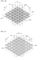
- Fig. 20 is an explanatory view of another configuration example of the periodic structure 41E of the light guide 4E of variation 5.
- the periodic structure 41E of Fig. 20 includes a diffraction grating constituted by the recessed or protruded parts 41ae in relation to the thickness direction of the body 40 arranged within the predetermined plane to have periodicity in the three predetermined directions A1, A2, A3.
- each recessed or protruded part 41ae is a protrusion with a triangle shape (regular triangle shape in figures) in its plan view.
- the recessed or protruded parts 41ae of Fig. 20 satisfy the aforementioned conditions (1) to (3).
- Fig. 21 is an explanatory view of another configuration example of the periodic structure 41E of the light guide 4E of variation 5.
- the periodic structure 41E of Fig. 21 includes a diffraction grating constituted by the recessed or protruded parts 41ae in relation to the thickness direction of the body 40 arranged within the predetermined plane to have periodicity in the three predetermined directions A1, A2, A3.
- each recessed or protruded part 41ae is a protrusion with a quadrilateral shape (parallelogram shape in the figure) in its plan view.
- the recessed or protruded parts 41ae of Fig. 21 satisfy the aforementioned conditions (1) to (3).
- the shapes of the recessed or protruded parts 41ae are not limited in particular.
- the recessed or protruded part 41ae may be a protrusion (protruded part) protruding in the thickness direction of the body 40, or a recessed part recessed in the thickness direction of the body 40.
- the recessed or protruded part 41ae have circular, polygonal, or other shapes in its plan view.
- the recessed or protruded parts 41ae can constitute the periodic structure 41E, they may be any of a group of protrusions (protruded parts), a group of recessed parts, or a combination of protruded parts and recessed parts. Further, when the aforementioned conditions (1) to (3) are satisfied, the intervals between the recessed or protruded parts 41ae in the predetermined direction A1, the predetermined direction A2, and the predetermined direction A3 may be different from each other. These points may similarly apply to the recessed or protruded parts 41a of the aforementioned embodiment and the recessed or protruded parts 41aa of variation 1.
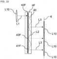
- Fig. 22 is an explanatory view of a configuration example of a periodic structure 41F of a light guide 4F of variation 6.
- the periodic structure 41F of Fig. 22 includes a volume holographic element (holographic diffraction grating) causing diffraction effect by periodic modulation of refractive indices.
- the periodic structure 41F includes a volume holographic element subject to multiple exposure to have periodicity in the three predetermined directions A1, A2, A3.
- the periodic structure 41F is formed inside the body 40.
- the periodic structure 41F includes a diffraction grating having a structure where portions having different refractive indices are arranged alternately.
- the periodic structure 41F of Fig. 22 includes an in-coupling region 42F and an exit region 43F.
- the in-coupling region 42F is a region on which the image light ray L1 from the display element 2 is incident, in the periodic structure 41F.
- the exit region 43F is a region which allows image light rays L3 to emerge toward the field of view region 6, in the periodic structure 41F and is a region other than the in-coupling region 42F, in the periodic structure 41F.
- the light guide 4F of Fig. 22 also reproduces the pupil L10 of the image right ray L1 to expand the pupil L10 by: dividing the image light ray L1 entering the body 40 from the in-coupling region 42F within the body 40 into the plurality of image light rays L2 propagating in the plurality of branch direction; and further dividing the plurality of image light rays L2 propagating in the plurality of branch directions into the plurality of mutually parallel image light rays L3 to allow them to emerge toward the field of view region 6.
- the periodic structure 41F includes the volume holographic element subject to multiple exposure to have periodicity in the three predetermined directions A1, A2, A3. This configuration enables downsizing the light guide 4F.
- the projection optical system 5 may be constituted by a plurality of optical elements.
- the plurality of optical elements may include a first compound lens where a negative meniscus lens and biconvex lens are combined, and a second compound lens where a positive meniscus lens and a negative meniscus lens are combined.
- the projection optical system 5 may not be limited if it can allow the image light ray L1 from the display element 2 to be incident on the light guide 4 with desired optical properties. Further, depending on cases, the projection optical system 5 may be omitted.
- the projection optical system 5 and the in-coupling region 42 of the light guide 4 are arranged in a straight line.
- the projection optical system 5 and the in-coupling region 42 of the light guide 4 are arranged in a straight line.
- the optical path of the image light ray L1 from the projection optical system 5 to the in-coupling region 42 of the light guide 4 always need not be straight.
- the image light ray L1 from the projection optical system 5 may be reflected by a reflective plate to be incident on the in-coupling region 42 of the light guide 4.
- the optical path of the image light ray L1 from the projection optical system 5 to the in-coupling region 42 of the light guide 4 is not straight but an L-shape, for example.
- the periodic structure may be configured to include a diffraction grating constituted by the recessed or protruded parts 41a arranged within the predetermined plane perpendicular to the thickness direction of the body 40 to have periodicity in the three predetermined directions A1, A2, A3, and a volume holographic element subject to multiple exposure to have periodicity in the three predetermined directions A1, A2, A3.
- the plurality of branch directions includes the first to third branch directions D1 to D3 and additionally the fourth branch direction D4.
- the plurality of branch directions includes the first to third branch directions D1 to D3 and additionally the fourth to sixth branch directions D4 to D6.
- the plurality of branch directions may include the first to third branch directions D1 to D3 and further include either one of the fifth branch direction D5 or the sixth branch direction D6 or any two of the fourth to sixth branch directions D4 to D6.
- the plurality of branch directions may further include at least one of the fourth, fifth, and sixth branch directions D4, D5, D6.
- each of the plurality of exit parts 44 but a predetermined exit part 44 of the plurality of exit parts 44 has the branch diffraction efficiency larger than the exit diffraction efficiency, the exit diffraction efficiency being an efficiency of diffracting the image light ray L2 propagating in the adjacent direction in which the in-coupling region 42 and the predetermined exit part 44 are adjacent to each other, into a direction toward the field of view region 6, and the branch diffraction efficiency being an efficiency of diffracting the image light ray L2 propagating in the adjacent direction into a predetermined branch direction different from the adjacent direction.
- the exit region 43 may include a part having a diffraction efficiency from the light guide 4 toward the field of view region 6, which becomes greater as further from the in-coupling region 42.
- at least one of the plurality of exit parts 44-1 to 44-4 may have a diffraction efficiency from the light guide 4 toward the field of view region 6, which becomes greater as further from the in-coupling region 42. This configuration enables improvement of uniformity of light intensity distribution at the field of view region 6.
- the diffraction efficiency from the light guide 4 toward the field of view region 6 is made greater as further from the in-coupling region 42 to decrease light intensity at a location closer to the in-coupling region 42 and increase light intensity at a location further from the in-coupling region 42. By doing so, it is possible to uniform light intensity distribution at the field of view region 6. Examples of how to adjust the diffraction efficiency into a direction toward the field of view region 6 may include adjustment of heights of the recessed or protruded parts 41a.
- the three predetermined directions A1, A2, A3 are, not limited thereto, directions not perpendicular to each other but intersecting each other in the predetermined plane perpendicular to the thickness direction of the body 40.
- at least two of the three predetermined directions A1, A2, A3 may be perpendicular to each other.
- the three predetermined directions A1, A2, A3 may be selected appropriately depending on usage of the optical system 3 or the like.
- the first aspect is an optical system (3) including a light guide (4; 4A; 4B; 4C; 4D; 4E; 4F) for guiding an image light ray (L1) which is output from a display element (2) and forms an image, to a field of view region (6) of a user as a virtual image.
- the light guide (4; 4A; 4B; 4C; 4D; 4E; 4F) includes a body (40; 40C) having a plate shape and a periodic structure (41; 41A; 41B; 41C; 41D; 41E; 41F) formed in the body (40; 40C).
- the periodic structure (41; 41A; 41B; 41C; 41D; 41E; 41F) has periodicity in three predetermined directions (A1, A2, A3) intersecting each other within a predetermined plane perpendicular to a thickness direction of the body (40; 40C).
- the periodic structure (41; 41A; 41B; 41C; 41D; 41E; 41F) includes an in-coupling region (42; 42B; 42C; 42D; 42F) dividing the image light ray (L1) incident from the display element (2) into a plurality of the image light rays and allowing the plurality of image light rays to propagate within the body (40; 40C) in a plurality of branch directions including first, second, and third branch directions (D1, D2, D3) respectively parallel to the three predetermined directions (A1, A2, A3), and an exit region (43; 43A; 43B; 43C; 43F) allowing the plurality of image light rays (L2) propagating in the plurality of branch directions within the body (40; 40C) to emerge from the body (40; 40C) toward the field of view region (6).
- This aspect enables downsizing the light guide (4; 4A; 4B; 4C; 4D; 4E; 4F).
- the second aspect is the optical system (3) based on the first aspect.
- the periodic structure (41; 41A; 41B; 41C; 41D; 41E; 41F) includes a diffraction grating constituted by recessed or protruded parts (41a; 41aa; 41ad; 41ae) in relation to the thickness direction of the body (40; 40C) which are arranged within the predetermined plane to have periodicity in the three predetermined directions (A1, A2, A3).
- This aspect enables simplification of the light guide (4; 4A; 4B; 4C; 4D; 4E; 4F).
- the third aspect is the optical system (3) based on the second aspect.
- the recessed or protruded parts (41a; 41aa; 41ad) are arranged within the predetermined plane in a hexagonal lattice. This aspect enables downsizing the light guide (4; 4A; 4B; 4C; 4D).
- the fourth aspect is the optical system (3) based on any one of the first to third aspects.
- the periodic structure (41F) includes a volume holographic element subject to multiple exposure to have periodicity in the three predetermined directions (A1, A2, A3). This aspect enables downsizing the light guide (4F).
- the fifth aspect is the optical system (3) based on any one of the first to fourth aspects.
- the in-coupling region (42; 42B; 42C; 42D; 42F) and the exit region (43; 43A; 43B; 43C; 43F) have the same periods in the three predetermined directions (A1, A2, A3), individually. This enables simplification of the structure of the light guide (4; 4A; 4B; 4C; 4D; 4E; 4F).
- the sixth aspect is the optical system (3) based on any one of the first to fifth aspects.
- the in-coupling region (42) and the exit region (43A) have different diffraction efficiencies in at least one of the plurality of branch directions. This aspect enable adjusting light intensity distribution at the field of view region (6).
- the seventh aspect is the optical system (3) based on any one of the first to sixth aspects.
- the exit region (43) includes a part having a diffraction efficiency from the light guide (4) toward the field of view region (6), which becomes greater as further from the in-coupling region (42). This aspect enable improvement of uniformity of light intensity distribution at the field of view region (6).
- the eighth aspect is the optical system (3) based on any one of the first to seventh aspects.
- the exit region (43A) includes a plurality of exit parts (44-1 to 44-4) adjacent to the in-coupling region (42) in the plurality of branch directions individually. At least two of the plurality of exit parts (44-1 to 44-4) have different diffraction efficiencies for incident light under a same condition. This aspect enable adjusting light intensity distribution at the field of view region (6).
- the ninth aspect is the optical system (3) based on the eighth aspect.
- at least two of the plurality of exit parts (44-1 to 44-4) are different in a direction of elements constituting the periodic structure (41B) but have a same periodicity. This aspect enable improvement of uniformity of light intensity distribution at the field of view region (6).
- a predetermined exit part of the plurality of exit parts (44-1 to 44-4) includes a region which has a branch diffraction efficiency larger than an exit diffraction efficiency.
- the exit diffraction efficiency is an efficiency of diffracting the image light ray (L2) propagating in an adjacent direction in which the in-coupling region (42) and the predetermined exit part are adj acent to each other, into a direction toward the field of view region (6).
- the branch diffraction efficiency is an efficiency of diffracting the image light ray (L2) propagating in the adjacent direction into a predetermined branch direction different from the adjacent direction.
- the eleventh aspect is the optical system (3) based on any one of the eighth to tenth aspects.
- at least one of the plurality of exit parts (44) includes recessed or protruded parts (41aa) arranged to have periodicity in the three predetermined directions (A1, A2, A3) within the predetermined plane.
- a ratio of a size of the recessed or protruded parts (41aa) relative to a period of arrangement of the recessed or protruded parts (41aa) is larger in a direction perpendicular to a branch direction different from a branch direction of the plurality of branch direction (D1, D2, D3, D4), in which a corresponding exit part is adjacent to the in-coupling region (42), than in a direction perpendicular to a branch direction of the plurality of the branch direction (D1, D2, D3, D4), in which the corresponding exit part is adjacent to the in-coupling region (42).
- the predetermined exit part includes recessed or protruded parts (41aa) arranged within the predetermined plane to have periodicity in the three predetermined directions (A1, A2, A3).
- a ratio of a size of the recessed or protruded parts (41aa) relative to a period of arrangement of the recessed or protruded parts (41aa) is larger in a direction perpendicular to the predetermined branch direction within the predetermined plane than in a direction perpendicular to the adjacent direction within the predetermined plane.
- the twelfth aspect is the optical system (3) based on any one of the first to eleventh aspects.
- wave vectors in the first, second, and third branch directions (D1, D2, D3) of the periodic structure (41; 41A; 41B; 41C; 41D; 41E; 41F) are denoted by k1, k2, and k3, respectively, and a maximum value of absolute values of the wave vectors in the first, second, and third branch directions (D1, D2, D3) is denoted by km
- the wave vectors k1, k2, and k3 satisfy a relation of
- the wave vectors k1, k2, and k3 satisfy a relation of
- the thirteenth aspect is the optical system (3) based on the twelfth aspect.
- the wave vectors k1, k2, and k3 satisfy a relation of
- 0. This configuration enables improvement of image quality.
- the fourteenth aspect is the optical system (3) based on the twelfth or thirteenth aspect.
- the absolute values of the wave vectors k1, k2, and k3 are identical to each other. This aspect enables arranging the pupils (L10) of the image light ray (L1) at a regular interval in the field of view region (6).
- the fifteenth aspect is the optical system (3) based on the twelfth or thirteenth aspect.
- two of the absolute values of the wave vectors k1, k2, and k3 are identical to each other. This aspect enables adjusting locations of the pupils (L10) of the image light ray (L1) in the field of view region (6).
- the sixteenth aspect is the optical system (3) based on the twelfth or thirteenth aspect.
- the absolute values of the wave vectors k1, k2, and k3 are different from each other. This aspect enables adjusting locations of the pupils (L10) of the image light ray (L1) in the field of view region (6).
- the seventeenth aspect is the optical system (3) based on any one of the first to sixteenth aspects.
- the light guide (4; 4A; 4B; 4C; 4D; 4E; 4F) reproduces a pupil (L10) of the image right ray (L1) to expand the pupil (L10) by: converting the image light ray (L1) entering the light guide (4; 4A; 4B; 4C; 4D; 4E; 4F) from the in-coupling region (42; 42B; 42C; 42D; 42F) into a plurality of image light rays (L2) in the plurality of branch directions allowed to propagate in the plurality of branch directions within the body (40; 40C); and dividing the plurality of image light rays into a plurality of mutually parallel image light rays (L3) in each of the plurality of branch directions to be allowed to emerge toward the field of view region (6).
- This aspect enables downsizing the light guide (4; 4A; 4B; 4C; 4D; 4E; 4F
- the eighteenth aspect is the optical system (3) based on any one of the first to seventeenth aspects.
- the in-coupling region (42; 42B; 42C; 42D; 42F) is arranged side by side with the exit region (43; 43A; 43B; 43C; 43F) in each of the three predetermined directions (A1, A2, A3).
- This aspect can improve transfer efficiency from the in-coupling region (42; 42B; 42C; 42D; 42F) to the exit region (43; 43A; 43B; 43C; 43F).
- the nineteenth aspect is the optical system (3) based on any one of the first to eighteenth aspect.
- the periodic structure (41; 41A; 41C; 41D; 41E; 41F) is formed not to include a region separating the in-coupling region (42; 42C; 42D; 42F) and the exit region (43; 43A; 43C; 43F) between the in-coupling region (42; 42C; 42D; 42F) and the exit region (43; 43A; 43C; 43F).
- This aspect enables simplification of the structure of the periodic structure (41; 41A; 41C; 41D; 41E; 41F).
- the twentieth aspect is the optical system (3) based on any one of the first to nineteenth aspects.
- the plurality of branch directions further include at least one of fourth, fifth, and sixth branch directions (D4, D5, D6).
- k4 is equal to -k1.
- k5 is equal to -k2.
- k6 is equal to -k3. This aspect enables expansion of the field of view region (6).
- the twenty-first aspect is the optical system (3) based on any one of the first to twentieth aspects.
- the optical system (3) further includes a projection optical system (5) allowing the image light ray (L1) to be incident on the in-coupling region (42; 42B; 42C; 42D; 42F) of the light guide (4; 4A; 4B; 4C; 4D; 4E; 4F) as a substantial collimate light ray.
- This aspect enables improvement of the use efficiency of the image light ray (L1).
- the twenty-second aspect is an image display device (1) including: the optical system (3) according to any one of the first to twenty-first aspects; and the display element (2). This aspect enables downsizing the light guide (4).
- the present disclosure is applicable to optical systems and image display devices.
- the present disclosure is applicable to an optical system for guiding light from a display element to a field of view region of a user, and an image display device including this optical system.
Landscapes
- Physics & Mathematics (AREA)
- General Physics & Mathematics (AREA)
- Optics & Photonics (AREA)
Applications Claiming Priority (2)
| Application Number | Priority Date | Filing Date | Title |
|---|---|---|---|
| JP2021096823 | 2021-06-09 | ||
| PCT/JP2022/017533 WO2022259756A1 (fr) | 2021-06-09 | 2022-04-11 | Système optique, et dispositif d'affichage d'image |
Publications (2)
| Publication Number | Publication Date |
|---|---|
| EP4354204A1 true EP4354204A1 (fr) | 2024-04-17 |
| EP4354204A4 EP4354204A4 (fr) | 2024-09-11 |
Family
ID=84425880
Family Applications (1)
| Application Number | Title | Priority Date | Filing Date |
|---|---|---|---|
| EP22819943.6A Pending EP4354204A4 (fr) | 2021-06-09 | 2022-04-11 | Système optique, et dispositif d'affichage d'image |
Country Status (5)
| Country | Link |
|---|---|
| US (1) | US20240111161A1 (fr) |
| EP (1) | EP4354204A4 (fr) |
| JP (1) | JP7811710B2 (fr) |
| CN (1) | CN117425850A (fr) |
| WO (1) | WO2022259756A1 (fr) |
Families Citing this family (1)
| Publication number | Priority date | Publication date | Assignee | Title |
|---|---|---|---|---|
| FI20245631A1 (en) * | 2024-05-17 | 2025-11-18 | Dispelix Oy | Screen structure |
Family Cites Families (12)
| Publication number | Priority date | Publication date | Assignee | Title |
|---|---|---|---|---|
| WO2008081070A1 (fr) * | 2006-12-28 | 2008-07-10 | Nokia Corporation | Dispositif pour étendre une pupille de sortie en deux dimensions |
| JP6171740B2 (ja) * | 2013-09-02 | 2017-08-02 | セイコーエプソン株式会社 | 光学デバイス及び画像表示装置 |
| GB2529003B (en) * | 2014-08-03 | 2020-08-26 | Wave Optics Ltd | Optical device |
| US10429645B2 (en) * | 2015-10-07 | 2019-10-01 | Microsoft Technology Licensing, Llc | Diffractive optical element with integrated in-coupling, exit pupil expansion, and out-coupling |
| GB201705160D0 (en) * | 2017-03-30 | 2017-05-17 | Wave Optics Ltd | Waveguide for an augmented reality or virtual reality display |
| CN113281839B (zh) | 2017-06-13 | 2023-04-14 | 伊奎蒂公司 | 具有扩大光分布重叠光栅的图像光导 |
| CN113325507A (zh) * | 2018-12-26 | 2021-08-31 | 上海鲲游光电科技有限公司 | 一种基于二维光栅的平面光波导 |
| JP7560887B2 (ja) * | 2019-04-16 | 2024-10-03 | ディスペリックス オサケ ユキチュア | 新規な格子配置 |
| JP7297548B2 (ja) * | 2019-06-21 | 2023-06-26 | 株式会社日立エルジーデータストレージ | 導光板の製造方法、導光板モジュールの製造方法、および画像表示装置の製造方法 |
| JP7352862B2 (ja) * | 2019-08-13 | 2023-09-29 | 大日本印刷株式会社 | 光学部材及び表示装置 |
| US10962787B1 (en) * | 2019-11-25 | 2021-03-30 | Shanghai North Ocean Photonics Co., Ltd. | Waveguide display device |
| CN111025657A (zh) * | 2019-12-31 | 2020-04-17 | 瑞声通讯科技(常州)有限公司 | 近眼显示装置 |
-
2022
- 2022-04-11 EP EP22819943.6A patent/EP4354204A4/fr active Pending
- 2022-04-11 JP JP2023527549A patent/JP7811710B2/ja active Active
- 2022-04-11 WO PCT/JP2022/017533 patent/WO2022259756A1/fr not_active Ceased
- 2022-04-11 CN CN202280040793.2A patent/CN117425850A/zh active Pending
-
2023
- 2023-12-07 US US18/532,148 patent/US20240111161A1/en active Pending
Also Published As
| Publication number | Publication date |
|---|---|
| US20240111161A1 (en) | 2024-04-04 |
| WO2022259756A1 (fr) | 2022-12-15 |
| JPWO2022259756A1 (fr) | 2022-12-15 |
| CN117425850A (zh) | 2024-01-19 |
| EP4354204A4 (fr) | 2024-09-11 |
| JP7811710B2 (ja) | 2026-02-06 |
Similar Documents
| Publication | Publication Date | Title |
|---|---|---|
| US10663734B2 (en) | Image display system | |
| EP4300165B1 (fr) | Guide d'ondes optique diffractif et dispositif d'affichage | |
| CN113219671B (zh) | 光学装置和显示设备 | |
| US9372347B1 (en) | Display system | |
| US11874503B1 (en) | Diffractive optical waveguide and display device | |
| US10133077B2 (en) | Luminous flux diameter enlarging element and display apparatus | |
| US11988838B2 (en) | Diffractive optical waveguide and display device | |
| JP2017528739A (ja) | 射出瞳を拡大する回折光導波路装置 | |
| JP2017156388A (ja) | 光束径拡大素子及び画像表示装置 | |
| CN114355502B (zh) | 衍射光栅波导和ar显示设备 | |
| US12436385B2 (en) | Diffractive optical waveguide, design method for diffractive optical waveguide, and display device | |
| US20240036257A1 (en) | Optical device | |
| US20230134576A1 (en) | Unpolarized light grating incoupler | |
| US12554057B2 (en) | Optical system and image display device | |
| EP4354204A1 (fr) | Système optique, et dispositif d'affichage d'image | |
| EP4502707A1 (fr) | Système optique et dispositif d'affichage d'image | |
| US20250116860A1 (en) | Optical system and image display device | |
| EP4354205A1 (fr) | Système optique, et dispositif d'affichage d'image | |
| CN115586636B (zh) | 一种光学扩瞳装置、设备、方法、显示设备 | |
| CN213544957U (zh) | 一种光学器件及其显示设备 | |
| EP4170412A1 (fr) | Dispositif optique, appareil d'affichage et procédé d'émission de lumière et d'affichage d'image associé | |
| US20250020933A1 (en) | Optical system and image display device | |
| CN217543546U (zh) | 波导结构 | |
| US20240231109A1 (en) | Optical system and image display device | |
| US20250224614A1 (en) | In-coupling meta-grating, out-coupling meta-grating, image combiner and ar optical system |
Legal Events
| Date | Code | Title | Description |
|---|---|---|---|
| STAA | Information on the status of an ep patent application or granted ep patent |
Free format text: STATUS: THE INTERNATIONAL PUBLICATION HAS BEEN MADE |
|
| PUAI | Public reference made under article 153(3) epc to a published international application that has entered the european phase |
Free format text: ORIGINAL CODE: 0009012 |
|
| STAA | Information on the status of an ep patent application or granted ep patent |
Free format text: STATUS: REQUEST FOR EXAMINATION WAS MADE |
|
| 17P | Request for examination filed |
Effective date: 20231215 |
|
| AK | Designated contracting states |
Kind code of ref document: A1 Designated state(s): AL AT BE BG CH CY CZ DE DK EE ES FI FR GB GR HR HU IE IS IT LI LT LU LV MC MK MT NL NO PL PT RO RS SE SI SK SM TR |
|
| A4 | Supplementary search report drawn up and despatched |
Effective date: 20240809 |
|
| RIC1 | Information provided on ipc code assigned before grant |
Ipc: G02B 27/01 20060101ALI20240805BHEP Ipc: G02B 5/18 20060101ALI20240805BHEP Ipc: G02B 27/02 20060101AFI20240805BHEP |
|
| DAV | Request for validation of the european patent (deleted) | ||
| DAX | Request for extension of the european patent (deleted) | ||
| STAA | Information on the status of an ep patent application or granted ep patent |
Free format text: STATUS: EXAMINATION IS IN PROGRESS |
|
| 17Q | First examination report despatched |
Effective date: 20260223 |
|
| STAA | Information on the status of an ep patent application or granted ep patent |
Free format text: STATUS: THE APPLICATION HAS BEEN WITHDRAWN |