EP4354238A1 - Procede de detection de collision pour une machine-outil - Google Patents
Procede de detection de collision pour une machine-outil Download PDFInfo
- Publication number
- EP4354238A1 EP4354238A1 EP23202757.3A EP23202757A EP4354238A1 EP 4354238 A1 EP4354238 A1 EP 4354238A1 EP 23202757 A EP23202757 A EP 23202757A EP 4354238 A1 EP4354238 A1 EP 4354238A1
- Authority
- EP
- European Patent Office
- Prior art keywords
- machining
- hood
- axis
- machining tool
- tool
- Prior art date
- Legal status (The legal status is an assumption and is not a legal conclusion. Google has not performed a legal analysis and makes no representation as to the accuracy of the status listed.)
- Pending
Links
Images


Classifications
-
- G—PHYSICS
- G05—CONTROLLING; REGULATING
- G05B—CONTROL OR REGULATING SYSTEMS IN GENERAL; FUNCTIONAL ELEMENTS OF SUCH SYSTEMS; MONITORING OR TESTING ARRANGEMENTS FOR SUCH SYSTEMS OR ELEMENTS
- G05B19/00—Program-control systems
- G05B19/02—Program-control systems electric
- G05B19/18—Numerical control [NC], i.e. automatically operating machines, in particular machine tools, e.g. in a manufacturing environment, so as to execute positioning, movement or co-ordinated operations by means of program data in numerical form
- G05B19/406—Numerical control [NC], i.e. automatically operating machines, in particular machine tools, e.g. in a manufacturing environment, so as to execute positioning, movement or co-ordinated operations by means of program data in numerical form characterised by monitoring or safety
- G05B19/4061—Avoiding collision or forbidden zones
-
- G—PHYSICS
- G05—CONTROLLING; REGULATING
- G05B—CONTROL OR REGULATING SYSTEMS IN GENERAL; FUNCTIONAL ELEMENTS OF SUCH SYSTEMS; MONITORING OR TESTING ARRANGEMENTS FOR SUCH SYSTEMS OR ELEMENTS
- G05B2219/00—Program-control systems
- G05B2219/30—Nc systems
- G05B2219/49—Nc machine tool, till multiple
- G05B2219/49042—Remove chips from probe, tool by blowing them away
-
- G—PHYSICS
- G05—CONTROLLING; REGULATING
- G05B—CONTROL OR REGULATING SYSTEMS IN GENERAL; FUNCTIONAL ELEMENTS OF SUCH SYSTEMS; MONITORING OR TESTING ARRANGEMENTS FOR SUCH SYSTEMS OR ELEMENTS
- G05B2219/00—Program-control systems
- G05B2219/30—Nc systems
- G05B2219/49—Nc machine tool, till multiple
- G05B2219/49157—Limitation, collision, interference, forbidden zones, avoid obstacles
Definitions
- the present invention relates to a method of detecting collision for a machine tool, particularly for a machine tool comprising a suction or blowing hood and a machining tool.
- the present invention also relates to a machine tool and a computer program product for controlling a machine tool.
- the invention relates to a gantry type machine for machining pieces made of wood or other materials such as plastic, glass, fiberglass, metal, ceramic and the like, comprising a control unit for detecting a potential collision between a portion of the suction or blowing hood and the machining tool, or between the suction or blowing hood and the work piece.
- the machining unit is supported by a gantry or cross-beam disposed over the work plane.
- a gantry may have, for example, an inverted "U” shape or an "L” shape.
- the machine comprises a tool store which houses various types of machining tools, which the machining unit can use by changing the machining tool as a function of the type of machining to be executed on the work piece.
- Each type of machining requires the execution, by the machine, of a series of operations or steps in order to complete such a specific machining.
- Each machining program is associated with a respective program for moving the machining unit, which comprises a series of sequential operations that the machine must perform on the work piece, so that the respective machining operation associated with that machining program is completed, and next machining program can be started.
- the machining unit comprises a suction or blowing hood that completely surrounds the machining unit itself and is capable of drawing or blowing away residual material derived from the machining of a work piece.
- machines which comprise reducible hoods, which can be extended, by means of pneumatic or electric actuation, along a direction of development orthogonal to the work plane, up to arriving in the vicinity of the work plane so as to facilitate the blowing or suctioning action.
- Another disadvantage is that the manual operation required for positioning the hood relative to the work plane does not allow the operator to continuously perform the design process, resulting for example in a delay in the design process and hence in the production of a machined work piece.
- a scope of the present invention to overcome said disadvantages by providing a collision detection method for a control unit of a machine tool, so as to detect a potential collision between the machining tool and the hood and, if necessary, adjusting a height of the hood with respect to a work plane so as to avoid a potential collision between the machining tool and the hood or between the hood and the piece to be machined.
- a further scope of the present invention is to provide the instruments necessary for carrying out the method and the apparatuses that perform this method.
- a specific object of the present invention is a collision detection method for a machine tool control unit as defined in claim 1, a machine tool as defined in claim 16 and a computer program product for controlling a machine tool as defined in claim 19.
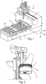
- the machine M comprises a base 3, extending along a first development axis X on which a work plane 33 is defined, on which one or more panels or other work pieces can rest and be fixed.
- the same machine M also comprises a gantry 4, i.e. a cross member, arranged above the work plane 33 and connected to the base 3 in a movable manner on a first axis X.
- a gantry 4 i.e. a cross member, arranged above the work plane 33 and connected to the base 3 in a movable manner on a first axis X.
- the gantry 4 may have, for example, an inverted U-shape or L-shape.
- a machining unit 41 is mounted in a movable manner along a second axis Y substantially orthogonal to the first axis X.
- the work plane 33 includes a plurality of bars 331, slidingly coupled to the base 3 along the first axis X.
- Each bar 33 comprises a plurality of locking means 332, in particular vacuum suction cups, to allow, in a known manner, to lock the work piece during machining.
- said locking means 332 are clamps or vices.
- the work plane 33 is a so-called a "multi-functional plane", i.e. a continuous plane provided with holes connected to a vacuum source, which by means of the insertion of suitable gaskets within grooves formed in the work plane itself, allows, in a known manner, to fix of the work piece to be machined.
- a multi-functional plane i.e. a continuous plane provided with holes connected to a vacuum source, which by means of the insertion of suitable gaskets within grooves formed in the work plane itself, allows, in a known manner, to fix of the work piece to be machined.
- the machining unit 41 is movable at least along a third axis Z (vertical) substantially orthogonal to the first axis X and to the second axis Y.
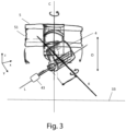
- the machining unit 41 can also rotate about a first rotation axis C and to a second rotation axis K, as shown for example in FIG. 3 . According to further variants, the machining unit 41 can rotate about three or more axes of rotation.
- movement means for example a conveyor belt
- movement means for example a conveyor belt
- moving means provide relative movement along the first axis X between said one or more panels or other pieces and the operating head 41.
- the machining unit 41 is depicted in FIG. 2 and comprises, in turn, a spindle 42 suitable to receive a tool for carrying out one or more machining operations on the work piece arranged on the work plane 33.
- a safety housing i.e. a safety structure arranged around the gantry 4, so as to provide coverage on at least three sides, while being movable integrally with the gantry 4 itself.
- the machine M also includes a tool store (not shown in the figures) for housing one or more tools, for performing, in a known manner, a change of tool.
- the tool store can be integrally connected to the gantry 4, for example at the outer side of a strut of the gantry 4, or arranged in a fixed manner on the base 3.
- the piece P can be essentially a panel such as furniture doors, or parquet panels made of wood, plastic, or any other material (e.g. plastic, glass, composite materials, ferrous materials), or a large panel for making wooden houses, or even a wooden beam, or an elongated wooden piece for making fixtures.
- a panel such as furniture doors, or parquet panels made of wood, plastic, or any other material (e.g. plastic, glass, composite materials, ferrous materials), or a large panel for making wooden houses, or even a wooden beam, or an elongated wooden piece for making fixtures.
- the machining unit 41 includes a machining tool.
- the machining tool 43 may include, for example, a tool with cutting elements, such as a milling cutter or a disk blade, a drill bit, a smoothing tool such as, for example, a rotary cutter or disc, a backing pad, or a brush.
- the machining tool 43 is configured, by means of the movement of the machining unit 41, to come into contact with the upper surface of the work piece P, arranged above a flat portion of the work plane 33.
- the machine M further comprises a suction or blowing hood 5 capable of drawing or blowing residual material derived from the machining of the work piece P.
- the hood 5 comprises a ring 50 to which is connected a cylindrical body 51, of the folding type, or the like, and a plurality of bristles 52 or flaps of plastic material, arranged along the perimeter of the ring 50 of the hood 5.
- the hood 5 generates an air movement so as to draw or blow away the residual material, such as debris, chips, dust and/or smoke produced by the machining process.
- the hood 5 can also be connected to a blowing system 6, such as a fan, able to input/eject air into/from the hood 5.
- a blowing system 6 such as a fan
- the hood 5 completely surrounds the machining unit 41 and can be extended or reduced along a direction of development O orthogonal to the work plane 33.
- the orthogonal development direction O may correspond with the first axis Z perpendicular to the work plane 33.
- the piece P is positioned and fixed on said work plane 33, in particular on said locking means 332.
- the machining unit 41 by means of the movement of the gantry 4 along the first axis X and by means of its movements along the second axis Y and/or the third axis Z, and/or the rotations around the first rotation axis C and/or the second rotation axis K, is positioned so as to execute the programmed machining on the work piece P, by means of the machining tool 43.
- the machine tool M further comprises a control unit in which the machining programs are stored and which commands the machining unit 41 as a function of them.
- the control unit thus has the task of coordinating the actions needed for the execution of one or more machine instruction to perform the collision detection method shown below with reference to FIG. 4 .
- the control unit may be operatively connected with a user interface to present an information indicative of the potential collision.
- a step of removing the residues resulting from the machining performed on the work piece P is performed, for example by blowing or suctioning action.
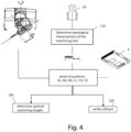
- FIG. 4 a method of detecting collision for a control unit of a machine tool M is depicted as described with respect to FIGS. 1-3 .
- the method for operating the machine M is performed as follows.
- the method may include an initial preparation step in which the machine tool M is supplied with a machining tool 43.
- the method further comprises a step of determining 110 a topological characteristic 44, 62 of the machining tool 43 of the machine M.
- the topological characteristic 44, 62 corresponds to an outer point disposed on the surface of the machining tool 43.
- the topological feature 44, 62 may include a protrusion or a recess along the surface of the machining tool 43.
- the protrusion may develop along a surface portion of the machining tool 43 and be of particular interest in order to determine a potential collision.
- the projection may comprise a maximum distance with respect to the longitudinal extension axis L being greater than or equal to the maximum distance from the longitudinal extension axis L of each of the remaining protrusions and/or recesses of the machining tool 43.
- the step of determining a topological characteristic 44, 62 may comprise the generation of a solid of revolution 6 corresponding to the machining tool 43 and the subsequent determination of a topological characteristic 62 of the solid of revolution 6 thus generated.
- the solid of revolution 6 is obtained by the rotation of the machining tool 43 around the longitudinal extension axis L of the machining tool 43.
- the topological characteristic 62 will be a point arranged on the surface of the solid of revolution 6, but in any case, corresponding to a topological characteristic of the machining tool 43, as shown for example in FIGS. 5A and 5B .
- the reference point R is arranged in correspondence of the topological feature 44, 62 as shown for example in FIG. 5A or 5B .
- the method may identify one or more reference points along the axis L, each corresponding to a determined topological characteristic of the solid of revolution 6 and/or the machining tool 43.
- the method further comprises a step of generating, by means of a sectional plane S passing through the determined reference point R, or selected, a first orthogonal projection 7 of the machining tool 43.
- the sectional plane S may be a plane orthogonal to the axis of longitudinal extension L of the machining tool, as shown, for example, in FIG. 5A or 5B .
- the projection may be performed on a projection plane PJ orthogonal to the direction of development O of the hood 5.
- the projection plane PJ may thus be a plane parallel to the projection plane 33.
- the projection plane PJ is shown in FIG. 7 .
- the first orthogonal projection 7 may comprise, for example, an orthogonal projection 7 on the projection plane PJ of the solid of revolution 6, so as to obtain a projection that represents the rotational movement of the machining tool 43 (also asymmetric) during the machining or use of the machine M.
- the orthogonal projection 7 may comprise one or more orthogonal projections obtained by one or more sectional planes S.
- the orthogonal projection 7 comprises (i) an orthogonal projection 7A corresponding to the projection obtained by means of a sectional plane S passing through the reference point RA along the longitudinal extension axis L of the machining tool 43, (ii) an orthogonal projection 7B corresponding to the projection obtained by means of a sectional plane S passing through the reference point RB along the longitudinal extension axis L of the machining tool 43, and (iii) an orthogonal projection 7C corresponding to the projection obtained by means of a sectional plane S passing through the reference point RC along the longitudinal extension axis L of the machining tool 43.
- the method further comprises generating a second orthogonal projection 8 on the projection plane PJ.
- the second orthogonal projection 8 corresponds to an orthogonal projection of the hood 5, for example the projection orthogonal to the projection plane PJ of the perimeter of the cylindrical body 51 of the hood 5 and/or of the bristles 52.
- the method further comprises a step of detecting 120 a potential collision between the machining tool 43 and the hood 5.
- the potential collision may be determined by a comparison between the first orthogonal projection 7 of the machining tool 43 (or solid of revolution 6) and a second orthogonal projection 8 of the hood 5 on the projection plane PJ.
- the comparison may be a positional comparison between the two projections.
- the method determines the presence of a potential collision between the machining tool 43 and the hood 5, in response to a determination that the minimum distance between the first orthogonal projection 7 and the second orthogonal projection 8 reaches a predetermined distance.
- the predetermined distance may include a distance greater than or equal to zero.
- a distance equal to zero may indicate that the first orthogonal projection 7 and the second orthogonal projection 8 intersect at a single point.
- the predetermined distance may be greater than zero so as to take into consideration any vibrations/movements of the machine M or of the components themselves of the machine M, for example vibrations/movements of the hood 5 and/or of the machining unit 41.
- Detecting a potential collision between the machining tool 43 and the hood 5, may further comprise determining that the first orthogonal projection 7 intersects the second orthogonal projection 8 of the hood in one or more points.
- the execution of the detection of a potential collision may be performed for each position of a first set of predetermined positions B1, B2, B3, and/or a second set of predetermined positions C1, C2, C3.
- the method comprises determining a first set of positions B1, B2, B3 representing a set of positions that the machining unit 41 assumes rotating around the axis of rotation C to perform a series of machining on the work piece P.
- the method may further comprise determining a second set of positions C1, C2, C3 representing a second set of positions that the machining tool 43 may assume about a second rotation axis K to perform machining on the work piece P.
- the orthogonal projections derived from the set of positions B1, B2, B3 and/or C1, C2, C3 can be considered as placed on each other or individually in order to detect a potential collision between the machining tool 43 and the hood 5.
- the first orthogonal projection 7 can correspond to the single orthogonal projection 7 obtained for each position placed on each other in such a way as to compare a combined orthogonal projection 7 with a second orthogonal projection 8 of the hood.
- the method may also include a step in which the control unit presents on the user interface connected thereto an information indicative of the potential collision detected between the machining tool 43 and the hood 5.
- the method may also comprise a step of determining the optimal machining height 130. This step comprises the determination of the height of the machining tool 43 with respect to a work plane 33 of the machine M and the determination of the optimal operative height of the hood 5.
- the height of the hood 5 can be adjusted with respect to the work plane 33 so that the height of the hood 5 is higher than the height of the machining tool 43, thus avoiding a potential collision between the machining tool 43 and the hood 5.
- the optimal height of the hood 5 can be defined so as not to exceed a threshold value with respect to the height of the machining tool 43.
- the height of the hood 5 can be functionally adjusted to the optimal machining height.
- the step of adjusting the height of the hood 5 can be carried out before performing any one or a sequence of operations on the work piece P to be machined.
- the adjustment of the height of hood 5 can be carried out before the machining unit 41 assumes a position of the first set of predetermined positions B1, B2, B3 and/or of the second set of predetermined positions C1, C2, C3.
- the method also includes a step in which the height of the hood 5 can be adjusted so as to avoid collisions between the hood 5, in particular the ring 50, which is connected below the bristles 52 and above the cylindrical body 51, and the piece P.
- the height of the work piece P to be machined is acquired and the height of the hood 5 is adjusted, so that the height of the ring 50 is greater than the height of the work piece P.
- the collision detection method for a machine tool control unit M allows to determine a potential collision between the hood 5 and the machining tool 43 of the machine M in a simple and efficient manner.
- the method further allows to determine an optimal height that facilitate efficient suction/blowing and prevents potential collisions between the hood 5 and the working tool 43 of the machine M, the height of the hood 5 can therefore be automatically adjusted in a simple and efficient manner.
Landscapes
- Engineering & Computer Science (AREA)
- Human Computer Interaction (AREA)
- Manufacturing & Machinery (AREA)
- Physics & Mathematics (AREA)
- General Physics & Mathematics (AREA)
- Automation & Control Theory (AREA)
- Auxiliary Devices For Machine Tools (AREA)
Applications Claiming Priority (1)
| Application Number | Priority Date | Filing Date | Title |
|---|---|---|---|
| IT102022000020943A IT202200020943A1 (it) | 2022-10-11 | 2022-10-11 | Metodo di rilevamento di collisione per una macchina utensile |
Publications (1)
| Publication Number | Publication Date |
|---|---|
| EP4354238A1 true EP4354238A1 (fr) | 2024-04-17 |
Family
ID=88237412
Family Applications (1)
| Application Number | Title | Priority Date | Filing Date |
|---|---|---|---|
| EP23202757.3A Pending EP4354238A1 (fr) | 2022-10-11 | 2023-10-10 | Procede de detection de collision pour une machine-outil |
Country Status (2)
| Country | Link |
|---|---|
| EP (1) | EP4354238A1 (fr) |
| IT (1) | IT202200020943A1 (fr) |
Citations (4)
| Publication number | Priority date | Publication date | Assignee | Title |
|---|---|---|---|---|
| JPS56146647A (en) * | 1980-04-18 | 1981-11-14 | Toshiba Mach Co Ltd | Chip suction device |
| US5339015A (en) * | 1991-11-07 | 1994-08-16 | Okuma Corporation | Interference checking method and apparatus for numerical control machining tool |
| JPH0871884A (ja) * | 1994-09-01 | 1996-03-19 | Sankyo Alum Ind Co Ltd | 集塵フード |
| US20010012973A1 (en) * | 1999-12-16 | 2001-08-09 | Peter Wehrli | Method and device for disturbance sensing, especially collision sensing, in the drive system of a numerically controlled machine tool |
-
2022
- 2022-10-11 IT IT102022000020943A patent/IT202200020943A1/it unknown
-
2023
- 2023-10-10 EP EP23202757.3A patent/EP4354238A1/fr active Pending
Patent Citations (4)
| Publication number | Priority date | Publication date | Assignee | Title |
|---|---|---|---|---|
| JPS56146647A (en) * | 1980-04-18 | 1981-11-14 | Toshiba Mach Co Ltd | Chip suction device |
| US5339015A (en) * | 1991-11-07 | 1994-08-16 | Okuma Corporation | Interference checking method and apparatus for numerical control machining tool |
| JPH0871884A (ja) * | 1994-09-01 | 1996-03-19 | Sankyo Alum Ind Co Ltd | 集塵フード |
| US20010012973A1 (en) * | 1999-12-16 | 2001-08-09 | Peter Wehrli | Method and device for disturbance sensing, especially collision sensing, in the drive system of a numerically controlled machine tool |
Also Published As
| Publication number | Publication date |
|---|---|
| IT202200020943A1 (it) | 2024-04-11 |
Similar Documents
| Publication | Publication Date | Title |
|---|---|---|
| JP4843238B2 (ja) | かさ歯車の歯の縁部を面取り及び/又はばり取りする方法 | |
| US9043011B2 (en) | Robotic machining apparatus method and system for turbine buckets | |
| CN102814706B (zh) | 自由形态切割机 | |
| US6390900B1 (en) | Finishing tool for CNC router machines | |
| US10414051B2 (en) | File translator system | |
| CN109475993A (zh) | 加工程序生成装置及加工方法 | |
| EP4008500B1 (fr) | Appareil de traitement | |
| US5547003A (en) | Device and method for forming square inside corners on raised panels formed of single workpieces | |
| JP2018030202A (ja) | 加工装置および加工方法 | |
| JP3969664B2 (ja) | 数値制御工作機械及び加工プログラムのチェック方法 | |
| US6089799A (en) | Surface finishing method and machine for the same | |
| US6099216A (en) | Profile processing method and processing machine therefor | |
| ITBO970266A1 (it) | Macchina operatrice e relatico processo, per la lavorazione di pannell i. | |
| JP6078194B1 (ja) | 木材プレカット加工装置 | |
| WO2022185640A1 (fr) | Programme, dispositif d'édition de données de cl et machine-outil | |
| EP3915726A1 (fr) | Machine pour travailler des pièces en bois comprenant un système laser et son procédé de fonctionnement | |
| EP3760400A1 (fr) | Procédé de création de trajet d'outil, dispositif de création de trajet d'outil, programme de création de trajet d'outil et support d'enregistrement sur lequel est enregistré un programme | |
| JPH1058279A (ja) | タレット工具選択指令方法 | |
| JP4398070B2 (ja) | 工作機械の数値制御装置および溝加工方法 | |
| EP1623805A1 (fr) | Machine à contrôle numérique pour la réalisation d'éléments de jonction | |
| JPH05337804A (ja) | 自動仕上げ装置 | |
| IT202200020943A1 (it) | Metodo di rilevamento di collisione per una macchina utensile | |
| JP7131454B2 (ja) | 数値制御装置、工作機械、制御プログラム、及び記憶媒体 | |
| JPH08267350A (ja) | バリ取り方法 | |
| JP6754870B1 (ja) | 工作機械および制御方法 |
Legal Events
| Date | Code | Title | Description |
|---|---|---|---|
| PUAI | Public reference made under article 153(3) epc to a published international application that has entered the european phase |
Free format text: ORIGINAL CODE: 0009012 |
|
| STAA | Information on the status of an ep patent application or granted ep patent |
Free format text: STATUS: THE APPLICATION HAS BEEN PUBLISHED |
|
| AK | Designated contracting states |
Kind code of ref document: A1 Designated state(s): AL AT BE BG CH CY CZ DE DK EE ES FI FR GB GR HR HU IE IS IT LI LT LU LV MC ME MK MT NL NO PL PT RO RS SE SI SK SM TR |
|
| STAA | Information on the status of an ep patent application or granted ep patent |
Free format text: STATUS: REQUEST FOR EXAMINATION WAS MADE |
|
| 17P | Request for examination filed |
Effective date: 20241009 |
|
| RBV | Designated contracting states (corrected) |
Designated state(s): AL AT BE BG CH CY CZ DE DK EE ES FI FR GB GR HR HU IE IS IT LI LT LU LV MC ME MK MT NL NO PL PT RO RS SE SI SK SM TR |
|
| GRAP | Despatch of communication of intention to grant a patent |
Free format text: ORIGINAL CODE: EPIDOSNIGR1 |
|
| STAA | Information on the status of an ep patent application or granted ep patent |
Free format text: STATUS: GRANT OF PATENT IS INTENDED |
|
| RIC1 | Information provided on ipc code assigned before grant |
Ipc: G05B 19/4061 20060101AFI20260702BHEP |
|
| INTG | Intention to grant announced |
Effective date: 20260714 |
|
| RIN1 | Information on inventor provided before grant (corrected) |
Inventor name: BILLI, DENIS |