EP4354605A1 - Zylindrische sekundärbatterie - Google Patents
Zylindrische sekundärbatterie Download PDFInfo
- Publication number
- EP4354605A1 EP4354605A1 EP23201353.2A EP23201353A EP4354605A1 EP 4354605 A1 EP4354605 A1 EP 4354605A1 EP 23201353 A EP23201353 A EP 23201353A EP 4354605 A1 EP4354605 A1 EP 4354605A1
- Authority
- EP
- European Patent Office
- Prior art keywords
- plate
- notch
- case
- secondary battery
- cylindrical secondary
- Prior art date
- Legal status (The legal status is an assumption and is not a legal conclusion. Google has not performed a legal analysis and makes no representation as to the accuracy of the status listed.)
- Pending
Links
Images


Classifications
-
- H—ELECTRICITY
- H01—ELECTRIC ELEMENTS
- H01M—PROCESSES OR MEANS, e.g. BATTERIES, FOR THE DIRECT CONVERSION OF CHEMICAL ENERGY INTO ELECTRICAL ENERGY
- H01M50/00—Constructional details or processes of manufacture of the non-active parts of electrochemical cells other than fuel cells, e.g. hybrid cells
- H01M50/10—Primary casings; Jackets or wrappings
- H01M50/147—Lids or covers
- H01M50/148—Lids or covers characterised by their shape
- H01M50/152—Lids or covers characterised by their shape for cells having curved cross-section, e.g. round or elliptic
-
- H—ELECTRICITY
- H01—ELECTRIC ELEMENTS
- H01M—PROCESSES OR MEANS, e.g. BATTERIES, FOR THE DIRECT CONVERSION OF CHEMICAL ENERGY INTO ELECTRICAL ENERGY
- H01M50/00—Constructional details or processes of manufacture of the non-active parts of electrochemical cells other than fuel cells, e.g. hybrid cells
- H01M50/10—Primary casings; Jackets or wrappings
- H01M50/102—Primary casings; Jackets or wrappings characterised by their shape or physical structure
- H01M50/107—Primary casings; Jackets or wrappings characterised by their shape or physical structure having curved cross-section, e.g. round or elliptic
-
- H—ELECTRICITY
- H01—ELECTRIC ELEMENTS
- H01M—PROCESSES OR MEANS, e.g. BATTERIES, FOR THE DIRECT CONVERSION OF CHEMICAL ENERGY INTO ELECTRICAL ENERGY
- H01M50/00—Constructional details or processes of manufacture of the non-active parts of electrochemical cells other than fuel cells, e.g. hybrid cells
- H01M50/10—Primary casings; Jackets or wrappings
- H01M50/147—Lids or covers
- H01M50/155—Lids or covers characterised by the material
- H01M50/157—Inorganic material
- H01M50/159—Metals
-
- H—ELECTRICITY
- H01—ELECTRIC ELEMENTS
- H01M—PROCESSES OR MEANS, e.g. BATTERIES, FOR THE DIRECT CONVERSION OF CHEMICAL ENERGY INTO ELECTRICAL ENERGY
- H01M50/00—Constructional details or processes of manufacture of the non-active parts of electrochemical cells other than fuel cells, e.g. hybrid cells
- H01M50/10—Primary casings; Jackets or wrappings
- H01M50/147—Lids or covers
- H01M50/166—Lids or covers characterised by the methods of assembling casings with lids
- H01M50/167—Lids or covers characterised by the methods of assembling casings with lids by crimping
-
- H—ELECTRICITY
- H01—ELECTRIC ELEMENTS
- H01M—PROCESSES OR MEANS, e.g. BATTERIES, FOR THE DIRECT CONVERSION OF CHEMICAL ENERGY INTO ELECTRICAL ENERGY
- H01M50/00—Constructional details or processes of manufacture of the non-active parts of electrochemical cells other than fuel cells, e.g. hybrid cells
- H01M50/10—Primary casings; Jackets or wrappings
- H01M50/172—Arrangements of electric connectors penetrating the casing
- H01M50/174—Arrangements of electric connectors penetrating the casing adapted for the shape of the cells
- H01M50/179—Arrangements of electric connectors penetrating the casing adapted for the shape of the cells for cells having curved cross-section, e.g. round or elliptic
-
- H—ELECTRICITY
- H01—ELECTRIC ELEMENTS
- H01M—PROCESSES OR MEANS, e.g. BATTERIES, FOR THE DIRECT CONVERSION OF CHEMICAL ENERGY INTO ELECTRICAL ENERGY
- H01M50/00—Constructional details or processes of manufacture of the non-active parts of electrochemical cells other than fuel cells, e.g. hybrid cells
- H01M50/10—Primary casings; Jackets or wrappings
- H01M50/183—Sealing members
-
- H—ELECTRICITY
- H01—ELECTRIC ELEMENTS
- H01M—PROCESSES OR MEANS, e.g. BATTERIES, FOR THE DIRECT CONVERSION OF CHEMICAL ENERGY INTO ELECTRICAL ENERGY
- H01M50/00—Constructional details or processes of manufacture of the non-active parts of electrochemical cells other than fuel cells, e.g. hybrid cells
- H01M50/10—Primary casings; Jackets or wrappings
- H01M50/183—Sealing members
- H01M50/186—Sealing members characterised by the disposition of the sealing members
- H01M50/188—Sealing members characterised by the disposition of the sealing members the sealing members being arranged between the lid and terminal
-
- H—ELECTRICITY
- H01—ELECTRIC ELEMENTS
- H01M—PROCESSES OR MEANS, e.g. BATTERIES, FOR THE DIRECT CONVERSION OF CHEMICAL ENERGY INTO ELECTRICAL ENERGY
- H01M50/00—Constructional details or processes of manufacture of the non-active parts of electrochemical cells other than fuel cells, e.g. hybrid cells
- H01M50/30—Arrangements for facilitating escape of gases
- H01M50/342—Non-re-sealable arrangements
- H01M50/3425—Non-re-sealable arrangements in the form of rupturable membranes or weakened parts, e.g. pierced with the aid of a sharp member
-
- H—ELECTRICITY
- H01—ELECTRIC ELEMENTS
- H01M—PROCESSES OR MEANS, e.g. BATTERIES, FOR THE DIRECT CONVERSION OF CHEMICAL ENERGY INTO ELECTRICAL ENERGY
- H01M50/00—Constructional details or processes of manufacture of the non-active parts of electrochemical cells other than fuel cells, e.g. hybrid cells
- H01M50/50—Current conducting connections for cells or batteries
- H01M50/531—Electrode connections inside a battery casing
- H01M50/533—Electrode connections inside a battery casing characterised by the shape of the leads or tabs
-
- H—ELECTRICITY
- H01—ELECTRIC ELEMENTS
- H01M—PROCESSES OR MEANS, e.g. BATTERIES, FOR THE DIRECT CONVERSION OF CHEMICAL ENERGY INTO ELECTRICAL ENERGY
- H01M50/00—Constructional details or processes of manufacture of the non-active parts of electrochemical cells other than fuel cells, e.g. hybrid cells
- H01M50/50—Current conducting connections for cells or batteries
- H01M50/531—Electrode connections inside a battery casing
- H01M50/538—Connection of several leads or tabs of wound or folded electrode stacks
-
- H—ELECTRICITY
- H01—ELECTRIC ELEMENTS
- H01M—PROCESSES OR MEANS, e.g. BATTERIES, FOR THE DIRECT CONVERSION OF CHEMICAL ENERGY INTO ELECTRICAL ENERGY
- H01M50/00—Constructional details or processes of manufacture of the non-active parts of electrochemical cells other than fuel cells, e.g. hybrid cells
- H01M50/50—Current conducting connections for cells or batteries
- H01M50/543—Terminals
-
- H—ELECTRICITY
- H01—ELECTRIC ELEMENTS
- H01M—PROCESSES OR MEANS, e.g. BATTERIES, FOR THE DIRECT CONVERSION OF CHEMICAL ENERGY INTO ELECTRICAL ENERGY
- H01M2200/00—Safety devices for primary or secondary batteries
- H01M2200/10—Temperature sensitive devices
- H01M2200/106—PTC
-
- H—ELECTRICITY
- H01—ELECTRIC ELEMENTS
- H01M—PROCESSES OR MEANS, e.g. BATTERIES, FOR THE DIRECT CONVERSION OF CHEMICAL ENERGY INTO ELECTRICAL ENERGY
- H01M2200/00—Safety devices for primary or secondary batteries
- H01M2200/20—Pressure-sensitive devices
-
- H—ELECTRICITY
- H01—ELECTRIC ELEMENTS
- H01M—PROCESSES OR MEANS, e.g. BATTERIES, FOR THE DIRECT CONVERSION OF CHEMICAL ENERGY INTO ELECTRICAL ENERGY
- H01M2220/00—Batteries for particular applications
- H01M2220/20—Batteries in motive systems, e.g. vehicle, ship, plane
-
- H—ELECTRICITY
- H01—ELECTRIC ELEMENTS
- H01M—PROCESSES OR MEANS, e.g. BATTERIES, FOR THE DIRECT CONVERSION OF CHEMICAL ENERGY INTO ELECTRICAL ENERGY
- H01M2220/00—Batteries for particular applications
- H01M2220/30—Batteries in portable systems, e.g. mobile phone, laptop
-
- H—ELECTRICITY
- H01—ELECTRIC ELEMENTS
- H01M—PROCESSES OR MEANS, e.g. BATTERIES, FOR THE DIRECT CONVERSION OF CHEMICAL ENERGY INTO ELECTRICAL ENERGY
- H01M50/00—Constructional details or processes of manufacture of the non-active parts of electrochemical cells other than fuel cells, e.g. hybrid cells
- H01M50/10—Primary casings; Jackets or wrappings
- H01M50/147—Lids or covers
- H01M50/166—Lids or covers characterised by the methods of assembling casings with lids
- H01M50/171—Lids or covers characterised by the methods of assembling casings with lids using adhesives or sealing agents
-
- Y—GENERAL TAGGING OF NEW TECHNOLOGICAL DEVELOPMENTS; GENERAL TAGGING OF CROSS-SECTIONAL TECHNOLOGIES SPANNING OVER SEVERAL SECTIONS OF THE IPC; TECHNICAL SUBJECTS COVERED BY FORMER USPC CROSS-REFERENCE ART COLLECTIONS [XRACs] AND DIGESTS
- Y02—TECHNOLOGIES OR APPLICATIONS FOR MITIGATION OR ADAPTATION AGAINST CLIMATE CHANGE
- Y02E—REDUCTION OF GREENHOUSE GAS [GHG] EMISSIONS, RELATED TO ENERGY GENERATION, TRANSMISSION OR DISTRIBUTION
- Y02E60/00—Enabling technologies; Technologies with a potential or indirect contribution to GHG emissions mitigation
- Y02E60/10—Energy storage using batteries
Definitions
- aspects of embodiments of the present disclosure relate to a cylindrical secondary battery.
- Secondary batteries are power storage systems that are capable of providing high energy density by converting electrical energy into chemical energy and storing the chemical energy.
- secondary batteries are designed to be rechargeable and, thus, are widely used in IT devices, such as smartphones, cellular phones, laptop computers, and tablet personal computers (PCs).
- IT devices such as smartphones, cellular phones, laptop computers, and tablet personal computers (PCs).
- PCs tablet personal computers
- Such secondary batteries desirably have certain characteristics, such as high density, high output power, and stability.
- Embodiments of the present disclosure provide a cylindrical secondary battery in which a cap plate has a vent having a central notch having a ring shape and a plurality of inner peripheral notches having a line shape extending outwardly from the central notch. Therefore, gas may be easily discharged through the cap plate when the vent fractures while preventing internal components from leaking out.
- a cylindrical secondary battery includes: an electrode assembly including a first electrode plate, a separator, and a second electrode plate; a case accommodating the electrode assembly and electrically connected to the second electrode plate; a terminal passing through a lower surface of the case and electrically connected to the first electrode plate; and a cap plate sealing an upper end portion of the case and having a vent.
- the vent is a thinner portion of the cap plate than other regions thereof and has a central notch having a ring shape and being at a central portion of the cap plate and an inner peripheral notch having a line shape extending from the central notch toward an edge of the cap plate.
- a first thickness is a thickness of the central notch, and a second thickness is a thickness of the inner peripheral notch.
- the first thickness may be less than or equal to the second thickness.
- the thickness of the central notch and the thickness of the inner peripheral notch may be in a range of 0.1 mm to 0.35 mm.
- the cylindrical secondary battery may further include: a first current collector plate having a circular plate shape corresponding to a lower surface of the electrode assembly and contacting and electrically connected to the first electrode plate exposed at the lower surface of the electrode assembly; and a second current collector plate having a circular plate shape corresponding to an upper surface of the electrode assembly and contacting and electrically connected to the second electrode plate exposed at the upper surface of the electrode assembly.
- the cap plate may be a circular metal plate and may have a central region over the second current collector plate and an edge region coupled to the case and protruding upwardly above the central region thereof.
- the vent may be in the central region.
- the case may have: a beading part recessed into the case below the cap plate; and a crimping part formed by the upper end portion of the case being bent inwardly to fix the edge region of the cap plate.
- the inner peripheral notch may include two to twelve inner peripheral notches that are spaced apart from each other at equal intervals around the central notch.
- the inner peripheral notches may be symmetrical to each other in a plan view with respect to the central notch.
- the cylindrical secondary battery may further include: a first gasket between the terminal and the case; and a second gasket between the cap plate and the case.
- the cap plate may be electrically insulated from the first electrode plate and the second electrode plate.
- the central notch may have an inner diameter of 2 mm to 9 mm.
- a width of an upper surface of the central notch and a width of an upper surface of the inner peripheral notch may be greater than a width of a lower surface thereof (e.g. a width of an upper surface of the central notch may be greater than a width of a lower surface of the central notch, and/or a width of an upper surface of the inner peripheral notch may be greater than a width of a lower surface of the inner peripheral notch).
- the central notch and the inner peripheral notch may have a two-stage or three-stage stepped portion shape (e.g. formed by performing forging twice or three times).
- the expression "at least one of a, b, or c" indicates only a, only b, only c, both a and b, both a and c, both b and c, all of a, b, and c, or variations thereof.
- the terms “use,” “using,” and “used” may be considered synonymous with the terms “utilize,” “utilizing,” and “utilized,” respectively.
- the terms “substantially,” “about,” and similar terms are used as terms of approximation and not as terms of degree, and are intended to account for the inherent variations in measured or calculated values that would be recognized by those of ordinary skill in the art.
- first, second, third, etc. may be used herein to describe various elements, components, regions, layers, and/or sections, these elements, components, regions, layers, and/or sections should not be limited by these terms. These terms are used to distinguish one element, component, region, layer, or section from another element, component, region, layer, or section. Thus, a first element, component, region, layer, or section discussed below could be termed a second element, component, region, layer, or section without departing from the teachings of example embodiments.
- spatially relative terms such as “beneath,” “below,” “lower,” “above,” “upper,” and the like, may be used herein for ease of description to describe one element or feature's relationship to another element(s) or feature(s) as illustrated in the figures. It will be understood that the spatially relative terms are intended to encompass different orientations of the device in use or operation in addition to the orientation depicted in the figures. For example, if the device in the figures is turned over, elements described as “below” or “beneath” other elements or features would then be oriented “above” or “over” the other elements or features. Thus, the term “below” may encompass both an orientation of above and below. The device may be otherwise oriented (rotated 90 degrees or at other orientations), and the spatially relative descriptors used herein should be interpreted accordingly.
- FIG. 1 is a perspective view of a cylindrical secondary battery 100 according to an embodiment of the present disclosure.
- FIG. 2 is a cross-sectional view of the cylindrical secondary battery 100 shown in FIG. 1 in a longitudinal direction.
- the cylindrical secondary battery 100 may include a case 110, an electrode assembly 120 accommodated in the case 110, a terminal 150 made of a rivet and coupled to a terminal hole (or terminal opening) formed in one end portion (e.g., in one end) of the case 110, and a cap plate 160 sealing an opening at the other end portion (e.g., the opposite end or the opposite end portion) of the case 110.
- the case 110 has a lower surface portion 111 having a circular shape and a side surface portion 112 extending upwardly from an edge (e.g., a peripheral edge) of the lower surface portion 111 to have a length.
- the lower surface portion 111 and the side surface portion 112 of the case 110 may be integrally formed.
- the lower surface portion 111 which has the circular shape, may have a flat circular plate shape and may have a terminal hole (e.g., a terminal opening) 111a formed to pass through a central portion thereof.
- the terminal 150 made of the rivet, may be inserted into and coupled to the lower surface portion 111 via the terminal hole 111a in the lower surface portion 111.
- a first gasket 115 may be interposed between the terminal hole 111a and the terminal 150 for sealing and electrical insulating therebetween. The first gasket 115 prevents contact between the terminal 150 and the case 110 to electrically separate (or electrically isolate) the terminal 150 from the case 110.
- the terminal hole 111a in the lower surface portion 111 of the case 110 may be sealed by the first gasket 115.
- the first gasket 115 may be made of a resin material, such as polyethylene (PE), polypropylene (PP), or polyethylene terephthalate (PET).
- the electrode assembly 120 may be inserted into the case 110 through the open upper end portion of the case 110 together with an electrolyte.
- the cap plate 160 may be coupled to the case 110 at the open upper end portion to seal the inside of the case 110.
- the electrolyte enables movement of lithium ions between a positive electrode plate 121 and a negative electrode plate 122 of the electrode assembly 120.
- the electrolyte may be a non-aqueous organic electrolyte that is a mixture of a lithium salt and a high-purity organic solvent.
- the electrolyte may be a polymer using (or including) a polyelectrolyte or a solid electrolyte, but the electrolyte is not limited thereto.
- the case 110 may be made of steel, a steel alloy, aluminium, an aluminium alloy, or an equivalent thereof, but a material thereof is not limited thereto.
- a beading part (e.g., a bead) 113 recessed into the case 110 may be formed below the cap plate 160 so that the electrode assembly 120 does not deviate to the outside, and a crimping part (e.g., a crimp) 114 bent inwardly may be formed on the cap plate 160.
- a crimping part e.g., a crimp
- the beading part 113 is formed after the electrode assembly 120 is inserted through the open upper end portion of the case 110 and prevents the electrode assembly 120 from being separated from the case 110.
- the electrode assembly 120 includes a first electrode plate 121, a second electrode plate 122, and a separator 123.
- the first electrode plate 121 may be the positive electrode plate
- the second electrode plate 122 may be the negative electrode plate.
- the reverse is also possible.
- an embodiment in which the first electrode plate 121 is the positive electrode plate, and the second electrode plate 122 is the negative electrode plate will be described.
- the first electrode plate 121 may be formed by coating at least one surface of a plate-shaped metal foil made of aluminium (Al) with a positive electrode active material, such as transition metal oxide.
- a positive electrode uncoated portion which is a portion of the plate-shaped metal foil that is not coated with a positive electrode active material may be provided at a lower end portion of the first electrode plate 121.
- the positive electrode uncoated portion may protrude in a downward direction of the electrode assembly 120 (e.g. in a direction towards the lower surface portion 111). That is, the positive electrode uncoated portion of the first electrode plate 121 may protrude downwardly (e.g. in a direction towards the lower surface portion 111) further than the second electrode plate 122 and the separator 123.
- the second electrode plate 122 may be formed by coating at least one surface of a plate-shaped metal foil made of copper (Cu) or nickel (Ni) with a negative electrode active material, such as graphite or carbon.
- a negative electrode uncoated portion which is a portion of the plate-shaped metal foil that is not coated with a negative electrode active material, may be provided at an upper end portion of the second electrode plate 122.
- the negative electrode uncoated portion may protrude in an upward direction of the electrode assembly 120 (e.g. in a direction away from the lower surface portion 111). That is, the negative electrode uncoated portion of the second electrode plate 122 may protrude upwardly (e.g. in a direction away from the lower surface portion 111) further than the first electrode plate 121 and the separator 123.
- the separator 123 may be made of PE or PP, but the present disclosure is not limited thereto.
- the separator prevents an electrical short circuit between the first electrode plate 121 and the second electrode plate 122 while enabling the movement of lithium ions therebetween.
- the electrode assembly 120 is wound from a winding end in an approximately cylindrical shape.
- the positive electrode uncoated portion may protrude downwardly (e.g. in a direction towards the lower surface portion 111) from the first electrode plate 121, and the negative electrode uncoated portion may protrude upwardly (e.g. in a direction away from the lower surface portion 111) from the second electrode plate 122.
- a first current collector plate 130 may be a circular metal plate having a shape corresponding to a lower surface of the electrode assembly 120.
- a planar size of the first current collector plate 130 may be less than or equal to a size of the lower surface of the electrode assembly 120.
- the first current collector plate 130 may be made of aluminium (Al).
- Al aluminium
- the first current collector plate 130 may be fixed and electrically connected to the first electrode plate 121 exposed at a lower portion of the electrode assembly 120 by welding.
- the first current collector plate 130 may be fixed and electrically connected to the terminal 150 by welding.
- the first current collector plate 130 acts as a passage for current flow between the first electrode plate 121 of the electrode assembly 120 and the terminal 150.
- a second current collector plate 140 may include a planar portion 141 having a circular shape and corresponding to an upper surface of the electrode assembly 120 and an extension portion 142 extending upwardly (e.g. in a direction away from the lower surface portion 111) from an edge of the planar portion 141.
- a lower surface of the planar portion 141 may be in contact with the upper surface of the electrode assembly 120.
- the planar portion 141 may be fixed and electrically connected to the second electrode plate 122 exposed at an upper portion of the electrode assembly 120 by welding.
- the extension portion 142 may extend upwardly (e.g. in a direction away from the lower surface portion 111) from the edge of the planar portion 141.
- the extension portion 142 may be in contact with and coupled to the beading part 113 of the case 110.
- the extension portion 142 may be coupled, by welding, while in contact with an inner surface of the beading part 113 of the case 110.
- a plurality of extension portions 142 may be provided to be spaced apart from each other along the edge of the planar portion 141.
- the second current collector plate 140 acts as a passage for current flow between the second electrode plate 122 of the electrode assembly 120 and the case 110.
- the case 110 may be (or may act as) a negative terminal.
- the terminal 150 may be inserted into the terminal hole 111a formed in the lower surface portion 111 of the case 110 and electrically connected to the first current collector plate 130.
- the terminal 150 may be (or may act as) a positive terminal.
- the terminal 150 and the case 110 may have different polarities.
- the terminal 150 may be made of the same material as the first current collector plate 130 and the first electrode plate 121 or may be made of a similar material.
- a diameter of a portion of the terminal 150 exposed below the case 110 and a diameter of a portion thereof positioned inside the case 110 may be greater than a diameter positioned thereof in the terminal hole 111a.
- the terminal 150 may include a head 151 that is the portion exposed below the case 110 and a fastening portion 152 that is the portion positioned inside the case 110 to face the electrode assembly 120.
- the terminal 150 may be coupled to the terminal hole 111a in the case 110 from outside to inside.
- the head 151 may be positioned outside the case 110.
- the fastening portion 152 may be press-deformed (e.g., press-molded) through riveting and pressed in a state in which the first gasket 115 is placed on the lower surface portion 111.
- the fastening portion 152 may have a diameter that gradually increases from the terminal hole 111a toward the inside of the case 110.
- the head 151 may be in close contact with a lower portion of the lower surface portion 111 with the first gasket 115 interposed therebetween.
- the first gasket 115 may be interposed between the terminal 150 and the terminal hole 111a to electrically insulate and seal the terminal 150 and the case 110 from each other.
- the terminal 150 may be electrically connected to the first electrode plate 121 of the electrode assembly through the first current collector plate 130.
- the cap plate 160 may be a circular metal plate and may be coupled to the upper end portion of the case 110. An upper surface of the cap plate 160 may be exposed to the outside. The cap plate 160 may be coupled to the upper end portion of the case 110 with a second gasket 116 interposed therebetween and, thus, may be prevented from being electrically connected to the case 110. The cap plate 160 may not be electrically connected to a positive electrode or a negative electrode of the electrode assembly 120 and, thus, may have no separate electrical polarity.
- the cap plate 160 may be fixed due to an edge region 162 thereof being positioned between the beading part 113 and the crimping part 114 of the case 110. More specifically, when the second gasket 116 is placed on the beading part 113 of the case 110, the cap plate 160 may be seated on the second gasket 116. Thereafter, the crimping part 114 of the case 110 is bent in an inward direction of the cap plate 160 to press the second gasket 116 and couple the cap plate 160 and the case 110.
- the second gasket 116 may be made of a resin material, such as PE, PP, or PET. The second gasket 116 may press the cap plate 160 against the case 110 to seal the cap plate 160 and may prevent the cap plate 160 from being separated from the case 110.
- the cap plate 160 may have a central region 161 positioned over the second current collector plate 140 and the edge region 162 interposed between the beading part 113 and the crimping part 114 of the case 110 and coupled to the case 110.
- the central region 161 may protrude in an inward direction of the case 110 further than the edge region 162.
- the edge region 162 of the cap plate 160 may be positioned at a higher level than the central region 161 (e.g., the central region 161 of the cap plate 160 may be depressed toward a center of the case 110 from the edge region 162).
- the cap plate 160 may also have a connection region 163 for connecting (or extending between) the central region 161 and the edge region 162.
- the connection region 163 may be inclined.
- the cap plate 160 has a vent 165 in the central region 161 configured to be opened by set (or reference) pressure.
- the vent 165 may be a thinner portion of the cap plate 160 than other regions of the cap plate 160.
- the vent 165 may be a notch formed downwardly (e.g. in a direction towards the lower surface portion 111) from the upper surface of the cap plate 160.
- FIG. 3 is a plan view of the cap plate 160 according to an embodiment.
- FIG. 4A is a cross-sectional view of the cap plate taken along the line 4a-4a in FIG. 3
- FIG. 4B is a cross-sectional view of the cap plate taken along the line 4b-4b in FIG. 3 .
- configurations of the cap plate 160 and the vent 165 will be described in detail with reference to FIGS. 3, 4A , and 4B .
- the vent 165 may have a central notch 165a having a ring shape formed at a central portion of the cap plate 160 and an inner peripheral notch 165b having a line (or linear) shape that extends outwardly from the central notch 165a.
- the central notch 165a may have a circular ring shape.
- the central notch 165a may have a quadrangular shape as shown in FIGS. 5B and 5C .
- the central notch 165a may have a polygonal shape other than a quadrangular shape, and a shape thereof may be variously changed. In addition, as shown in FIGS.
- the inner peripheral notches 165b may extend outwardly from corners (e.g., vertices) of the central notch 165a, respectively, or may extend outwardly from a center of a side (e.g., of a linear side) thereof, but the present disclosure is not limited thereto.
- inner peripheral notches 165b may be provided as shown in FIG. 5A .
- a plurality of inner peripheral notches 165b may be provided.
- the plurality of inner peripheral notches 165b may be spaced apart from each other at equal intervals around the central notch 165a.
- two to twelve inner peripheral notches 165b may be spaced apart from each other at equal intervals around the central notch 165a.
- the central notch 165a and the inner peripheral notch 165b may be formed by performing pressing and forging operations two or three times in a notch press process.
- FIGS. 6A and 6B are enlarged views illustrating the portion C in FIG. 4B according to various embodiments.
- FIGS. 6A and 6B are enlarged views illustrating a cross section of the central notch 165a according to various embodiments.
- a cross section of the inner peripheral notch 165b may have the same structure as the cross section of the central notch 165a.
- a two-stage stepped portion e.g., a double step structure
- a three-stage stepped portion e.g., a triple step structure
- a first width Wa of the central notch 165a and the inner peripheral notch 165b may be greater than a second width Wb, that is, a width thereof at a lower portion adjacent to (e.g., nearer to) a lower surface of the cap plate 160.
- the first width Wa may be about 1.5 mm or less, and the second width Wb may be about 0.1 mm or less.
- the first width Wa and the second width Wb may be greater than 0, and the second width Wb may be less than the first width Wa without limitation.
- a first depth Ha of the central notch 165a may be greater than or equal to a second depth Hb of the inner peripheral notch 165b.
- the first depth Ha may be a height from the upper surface of the cap plate 160 to the lowest point of the central notch 165a.
- the second depth Hb may be a height that is a depth of the inner peripheral notch 165b from the upper surface of the cap plate 160 to the lowest point of the inner peripheral notch 165b.
- the first thickness Ta may be a thickness from the lowest point of the central notch 165a to the lower surface of the cap plate 160
- the second thickness Tb may be a thickness from the lowest point of the inner peripheral notch 165b to the lower surface of the cap plate 160.
- the first thickness Ta of the central notch 165a may be less than the second thickness Tb of the inner peripheral notch 165b.
- the same forging process may be used to form both the central notch 165a and the inner peripheral notch 165b together, thereby reducing manufacturing costs and complexity.
- the first thickness Ta of the central notch 165a and the second thickness Tb of the inner peripheral notch 165b may be in a range of about 0.10 mm to about 0.35 mm.
- first thickness Ta of the central notch 165a and the second thickness Tb of the inner peripheral notch 165b are less than about 0.10 mm, deformation or cracks may occur in the vent 165 in the cap plate 160.
- first thickness Ta of the central notch 165a and the second thickness Tb of the inner peripheral notch 165b exceed about 0.35 mm, the central notch 165a and the inner peripheral notch 165b may not fracture even when exposed to relatively high pressure and, thus, may not operate as the vent 165.
- FIG. 7 shows experimental results of fracture pressure according to a thickness of the vent in the cylindrical secondary battery shown in FIGS. 1 and 2 .
- the vent 165 may fracture when the internal pressure in the case 110 is 12 kgf/cm 2 .
- the vent 165 may fracture when the internal pressure of the case 110 is 18 kgf/cm 2 .
- a thickness from the upper surface to the lower surface of the central region 161 of the cap plate 160 may be in a range of about 0.7 mm to about 1.2 mm.
- FIGS. 8A and 8B are cross-sectional views and plan views, respectively, of the cap plate before and after the central notch and the inner peripheral notch of the cylindrical secondary battery shown in FIGS. 1 and 2 fracture.
- FIGS. 8A and 8B when internal pressure of the case 110 increases, the central notch 165a fractures, and if the internal pressure is continuously generated (or continues to increase), the inner peripheral notch 165b fractures. Thus, gas and heat can be easily discharged through the cap plate 160 due to an increase in the fracture area.
- FIG. 9 is a photograph of three cylindrical secondary batteries 100 showing results in which a vent 165 fractures due to an increase in internal pressure in a case 110.
- the vent 165 of the cylindrical secondary battery 100 includes a central notch 165a and an inner peripheral notch 165b, even when the vent 165 in a cap plate 160 fractures, internal components of the cylindrical secondary battery 100, such as a second current collector plate 140 inside the case 110, can be prevented from leaking out.
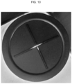
- FIG. 10 as a comparative example, a result of fracture of a vent of a cap plate that does not have a central notch is shown. As shown in FIG. 10 , when the internal pressure in a case increases, the notch fracture, but due to its small fracture area, internal gas and hot air may not be easily discharged through the cap plate.
- a vent 165 includes a central notch 165a and an inner peripheral notch 165b, when the internal pressure in a case 110 increases, an opening region (or fractured region) increases, thereby facilitating gas discharge.
- the inner peripheral notch 165b fractures in a line shape, thereby preventing components, such as a second current collector plate 140, from leaking out (e.g., from passing through the cap plate 160).
- the central notch 165a may have an inner diameter of about 2 mm to about 9 mm.
- the inner diameter of the central notch 165a exceeds about 9 mm, the second current collector plate 140 accommodated inside the case 110 may deviate to the outside due to internal pressure.
- the inner diameter of the central notch 165a is less than about 2 mm, internal gas may not be easily discharged and it may be difficult process (or form) the central notch due to a decrease in fracture area.
- a vent 165 includes a central notch 165a having a ring shape and a plurality of inner peripheral notches 165b having a line shape extending outwardly from the central notch 165a.
- gas can be easily discharged, and at the same time, internal components can be prevented from leaking out.
- cylindrical secondary batteries 100 each have both a negative electrode and a positive electrode (e.g., negative and positive terminals) at a lower surface thereof, the plurality of cylindrical secondary batteries 100 need only be connected (e.g., electrically connected) together at the lower surfaces thereof when electrically connected through a bus bar.
- a bus bar connection structure can be simplified.
- a vent provided in a cap plate has a central notch having a ring shape and a plurality of inner peripheral notches having a line shape extending outwardly from the central notch, gas may be easily discharged when the vent fractures while internal components are prevented from leaking outside.
- cylindrical secondary batteries according to various embodiments of the present disclosure each have both a negative electrode and a positive electrode (e.g., a negative terminal and a positive terminal) at a lower surface thereof, the plurality of cylindrical secondary batteries need only be connected at the lower surfaces thereof when electrically connected through a bus bar.
- a bus bar connection structure can be simplified.
Landscapes
- Chemical & Material Sciences (AREA)
- Chemical Kinetics & Catalysis (AREA)
- Electrochemistry (AREA)
- General Chemical & Material Sciences (AREA)
- Inorganic Chemistry (AREA)
- Sealing Battery Cases Or Jackets (AREA)
Applications Claiming Priority (1)
| Application Number | Priority Date | Filing Date | Title |
|---|---|---|---|
| KR1020220129382A KR102902224B1 (ko) | 2022-10-11 | 2022-10-11 | 원통형 이차 전지 |
Publications (1)
| Publication Number | Publication Date |
|---|---|
| EP4354605A1 true EP4354605A1 (de) | 2024-04-17 |
Family
ID=88241351
Family Applications (1)
| Application Number | Title | Priority Date | Filing Date |
|---|---|---|---|
| EP23201353.2A Pending EP4354605A1 (de) | 2022-10-11 | 2023-10-03 | Zylindrische sekundärbatterie |
Country Status (4)
| Country | Link |
|---|---|
| US (1) | US20240120609A1 (de) |
| EP (1) | EP4354605A1 (de) |
| KR (1) | KR102902224B1 (de) |
| CN (1) | CN117878494A (de) |
Cited By (2)
| Publication number | Priority date | Publication date | Assignee | Title |
|---|---|---|---|---|
| EP4517894A1 (de) * | 2023-08-31 | 2025-03-05 | Samsung Sdi Co., Ltd. | Zylindrische sekundärbatterie |
| EP4641783A1 (de) * | 2024-04-26 | 2025-10-29 | SK On Co., Ltd. | Batteriezelle und herstellungsverfahren dafür |
Families Citing this family (1)
| Publication number | Priority date | Publication date | Assignee | Title |
|---|---|---|---|---|
| WO2026084199A1 (ko) * | 2024-10-17 | 2026-04-23 | 주식회사 엘지에너지솔루션 | 배터리 셀, 이를 포함하는 배터리 팩 및 자동차 |
Citations (2)
| Publication number | Priority date | Publication date | Assignee | Title |
|---|---|---|---|---|
| US20180159100A1 (en) * | 2015-06-05 | 2018-06-07 | Lg Chem, Ltd. | Cap assembly for secondary battery |
| US11456512B2 (en) * | 2017-06-28 | 2022-09-27 | Byd Company Limited | Battery cover plate assembly, single cell battery, battery module, power battery pack, and electric car |
Family Cites Families (9)
| Publication number | Priority date | Publication date | Assignee | Title |
|---|---|---|---|---|
| US5853912A (en) * | 1996-07-10 | 1998-12-29 | Saft America, Inc. | Lithium ion electrochemical cell with safety valve electrical disconnect |
| JP4346637B2 (ja) * | 2006-11-24 | 2009-10-21 | 日立ビークルエナジー株式会社 | 円筒型二次電池 |
| US8486546B2 (en) * | 2008-12-01 | 2013-07-16 | Samsung Sdi Co., Ltd. | Cap assembly and secondary battery using the same with notched vent member |
| EP2419946B1 (de) * | 2009-04-15 | 2016-04-13 | Johnson Controls Saft Advanced Power Solutions LLC | Lüftung für elektrochemische zellen |
| KR101023880B1 (ko) * | 2009-06-08 | 2011-03-22 | 삼성에스디아이 주식회사 | 이차 전지 |
| KR102052063B1 (ko) * | 2013-01-11 | 2019-12-04 | 삼성에스디아이 주식회사 | 이차 전지 |
| KR102232530B1 (ko) * | 2014-08-11 | 2021-03-26 | 삼성에스디아이 주식회사 | 이차 전지 |
| US11978919B2 (en) * | 2018-07-13 | 2024-05-07 | HYDRO-QUéBEC | Battery safety vent assembly |
| US12407028B2 (en) * | 2021-02-19 | 2025-09-02 | Lg Energy Solution, Ltd. | Electrode assembly, battery, and battery pack and vehicle including the same |
-
2022
- 2022-10-11 KR KR1020220129382A patent/KR102902224B1/ko active Active
-
2023
- 2023-08-09 US US18/447,080 patent/US20240120609A1/en active Pending
- 2023-09-28 CN CN202311278671.XA patent/CN117878494A/zh active Pending
- 2023-10-03 EP EP23201353.2A patent/EP4354605A1/de active Pending
Patent Citations (2)
| Publication number | Priority date | Publication date | Assignee | Title |
|---|---|---|---|---|
| US20180159100A1 (en) * | 2015-06-05 | 2018-06-07 | Lg Chem, Ltd. | Cap assembly for secondary battery |
| US11456512B2 (en) * | 2017-06-28 | 2022-09-27 | Byd Company Limited | Battery cover plate assembly, single cell battery, battery module, power battery pack, and electric car |
Cited By (2)
| Publication number | Priority date | Publication date | Assignee | Title |
|---|---|---|---|---|
| EP4517894A1 (de) * | 2023-08-31 | 2025-03-05 | Samsung Sdi Co., Ltd. | Zylindrische sekundärbatterie |
| EP4641783A1 (de) * | 2024-04-26 | 2025-10-29 | SK On Co., Ltd. | Batteriezelle und herstellungsverfahren dafür |
Also Published As
| Publication number | Publication date |
|---|---|
| KR20240049909A (ko) | 2024-04-18 |
| KR102902224B1 (ko) | 2025-12-22 |
| US20240120609A1 (en) | 2024-04-11 |
| CN117878494A (zh) | 2024-04-12 |
Similar Documents
| Publication | Publication Date | Title |
|---|---|---|
| US12580260B2 (en) | Cylindrical secondary battery | |
| EP4468506A1 (de) | Sekundärbatterie | |
| EP4354605A1 (de) | Zylindrische sekundärbatterie | |
| US20240274933A1 (en) | Cylindrical secondary battery | |
| US20230231284A1 (en) | Secondary battery | |
| US20230253568A1 (en) | Secondary battery | |
| US20240274924A1 (en) | Cylindrical secondary battery | |
| EP4362178A1 (de) | Zylindrische sekundärbatterie | |
| US20240162501A1 (en) | Cylindrical secondary battery | |
| US20230231236A1 (en) | Secondary battery | |
| KR102950675B1 (ko) | 원통형 이차 전지 | |
| US20240356150A1 (en) | Secondary battery | |
| US20240186587A1 (en) | Cylindrical secondary battery | |
| EP4604278A1 (de) | Kappenanordnung und sekundärbatterie mit einer kappenanordnung | |
| US20250266536A1 (en) | Secondary battery | |
| US20250372775A1 (en) | Secondary battery | |
| US20250210829A1 (en) | Rechargeable battery | |
| US20260081324A1 (en) | Secondary battery | |
| US20240356186A1 (en) | Secondary battery |
Legal Events
| Date | Code | Title | Description |
|---|---|---|---|
| PUAI | Public reference made under article 153(3) epc to a published international application that has entered the european phase |
Free format text: ORIGINAL CODE: 0009012 |
|
| STAA | Information on the status of an ep patent application or granted ep patent |
Free format text: STATUS: REQUEST FOR EXAMINATION WAS MADE |
|
| 17P | Request for examination filed |
Effective date: 20231003 |
|
| AK | Designated contracting states |
Kind code of ref document: A1 Designated state(s): AL AT BE BG CH CY CZ DE DK EE ES FI FR GB GR HR HU IE IS IT LI LT LU LV MC ME MK MT NL NO PL PT RO RS SE SI SK SM TR |