EP4517894A1 - Zylindrische sekundärbatterie - Google Patents
Zylindrische sekundärbatterie Download PDFInfo
- Publication number
- EP4517894A1 EP4517894A1 EP24192224.4A EP24192224A EP4517894A1 EP 4517894 A1 EP4517894 A1 EP 4517894A1 EP 24192224 A EP24192224 A EP 24192224A EP 4517894 A1 EP4517894 A1 EP 4517894A1
- Authority
- EP
- European Patent Office
- Prior art keywords
- vent
- cap plate
- area
- secondary battery
- linear
- Prior art date
- Legal status (The legal status is an assumption and is not a legal conclusion. Google has not performed a legal analysis and makes no representation as to the accuracy of the status listed.)
- Pending
Links
Images




Classifications
-
- H—ELECTRICITY
- H01—ELECTRIC ELEMENTS
- H01M—PROCESSES OR MEANS, e.g. BATTERIES, FOR THE DIRECT CONVERSION OF CHEMICAL ENERGY INTO ELECTRICAL ENERGY
- H01M10/00—Secondary cells; Manufacture thereof
- H01M10/04—Construction or manufacture in general
- H01M10/0422—Cells or battery with cylindrical casing
-
- H—ELECTRICITY
- H01—ELECTRIC ELEMENTS
- H01M—PROCESSES OR MEANS, e.g. BATTERIES, FOR THE DIRECT CONVERSION OF CHEMICAL ENERGY INTO ELECTRICAL ENERGY
- H01M50/00—Constructional details or processes of manufacture of the non-active parts of electrochemical cells other than fuel cells, e.g. hybrid cells
- H01M50/30—Arrangements for facilitating escape of gases
- H01M50/342—Non-re-sealable arrangements
- H01M50/3425—Non-re-sealable arrangements in the form of rupturable membranes or weakened parts, e.g. pierced with the aid of a sharp member
-
- H—ELECTRICITY
- H01—ELECTRIC ELEMENTS
- H01M—PROCESSES OR MEANS, e.g. BATTERIES, FOR THE DIRECT CONVERSION OF CHEMICAL ENERGY INTO ELECTRICAL ENERGY
- H01M50/00—Constructional details or processes of manufacture of the non-active parts of electrochemical cells other than fuel cells, e.g. hybrid cells
- H01M50/10—Primary casings; Jackets or wrappings
- H01M50/102—Primary casings; Jackets or wrappings characterised by their shape or physical structure
- H01M50/107—Primary casings; Jackets or wrappings characterised by their shape or physical structure having curved cross-section, e.g. round or elliptic
-
- H—ELECTRICITY
- H01—ELECTRIC ELEMENTS
- H01M—PROCESSES OR MEANS, e.g. BATTERIES, FOR THE DIRECT CONVERSION OF CHEMICAL ENERGY INTO ELECTRICAL ENERGY
- H01M50/00—Constructional details or processes of manufacture of the non-active parts of electrochemical cells other than fuel cells, e.g. hybrid cells
- H01M50/10—Primary casings; Jackets or wrappings
- H01M50/147—Lids or covers
- H01M50/148—Lids or covers characterised by their shape
-
- H—ELECTRICITY
- H01—ELECTRIC ELEMENTS
- H01M—PROCESSES OR MEANS, e.g. BATTERIES, FOR THE DIRECT CONVERSION OF CHEMICAL ENERGY INTO ELECTRICAL ENERGY
- H01M50/00—Constructional details or processes of manufacture of the non-active parts of electrochemical cells other than fuel cells, e.g. hybrid cells
- H01M50/10—Primary casings; Jackets or wrappings
- H01M50/147—Lids or covers
- H01M50/148—Lids or covers characterised by their shape
- H01M50/152—Lids or covers characterised by their shape for cells having curved cross-section, e.g. round or elliptic
-
- H—ELECTRICITY
- H01—ELECTRIC ELEMENTS
- H01M—PROCESSES OR MEANS, e.g. BATTERIES, FOR THE DIRECT CONVERSION OF CHEMICAL ENERGY INTO ELECTRICAL ENERGY
- H01M50/00—Constructional details or processes of manufacture of the non-active parts of electrochemical cells other than fuel cells, e.g. hybrid cells
- H01M50/10—Primary casings; Jackets or wrappings
- H01M50/147—Lids or covers
- H01M50/155—Lids or covers characterised by the material
- H01M50/157—Inorganic material
- H01M50/159—Metals
-
- H—ELECTRICITY
- H01—ELECTRIC ELEMENTS
- H01M—PROCESSES OR MEANS, e.g. BATTERIES, FOR THE DIRECT CONVERSION OF CHEMICAL ENERGY INTO ELECTRICAL ENERGY
- H01M50/00—Constructional details or processes of manufacture of the non-active parts of electrochemical cells other than fuel cells, e.g. hybrid cells
- H01M50/10—Primary casings; Jackets or wrappings
- H01M50/147—Lids or covers
- H01M50/166—Lids or covers characterised by the methods of assembling casings with lids
- H01M50/167—Lids or covers characterised by the methods of assembling casings with lids by crimping
-
- Y—GENERAL TAGGING OF NEW TECHNOLOGICAL DEVELOPMENTS; GENERAL TAGGING OF CROSS-SECTIONAL TECHNOLOGIES SPANNING OVER SEVERAL SECTIONS OF THE IPC; TECHNICAL SUBJECTS COVERED BY FORMER USPC CROSS-REFERENCE ART COLLECTIONS [XRACs] AND DIGESTS
- Y02—TECHNOLOGIES OR APPLICATIONS FOR MITIGATION OR ADAPTATION AGAINST CLIMATE CHANGE
- Y02E—REDUCTION OF GREENHOUSE GAS [GHG] EMISSIONS, RELATED TO ENERGY GENERATION, TRANSMISSION OR DISTRIBUTION
- Y02E60/00—Enabling technologies; Technologies with a potential or indirect contribution to GHG emissions mitigation
- Y02E60/10—Energy storage using batteries
-
- Y—GENERAL TAGGING OF NEW TECHNOLOGICAL DEVELOPMENTS; GENERAL TAGGING OF CROSS-SECTIONAL TECHNOLOGIES SPANNING OVER SEVERAL SECTIONS OF THE IPC; TECHNICAL SUBJECTS COVERED BY FORMER USPC CROSS-REFERENCE ART COLLECTIONS [XRACs] AND DIGESTS
- Y02—TECHNOLOGIES OR APPLICATIONS FOR MITIGATION OR ADAPTATION AGAINST CLIMATE CHANGE
- Y02P—CLIMATE CHANGE MITIGATION TECHNOLOGIES IN THE PRODUCTION OR PROCESSING OF GOODS
- Y02P70/00—Climate change mitigation technologies in the production process for final industrial or consumer products
- Y02P70/50—Manufacturing or production processes characterised by the final manufactured product
Definitions
- aspects of some embodiments of the present disclosure relate to a cylindrical secondary battery.
- Secondary batteries are batteries that can be charged and discharged, unlike primary batteries that cannot be recharged.
- Low-capacity secondary batteries are used in small and portable electronic devices such as smartphones, feature phones, tablet computers, notebook computers, digital cameras, and camcorders, while high-capacity secondary batteries are widely used as batteries for driving motors and storing power in hybrid vehicles, electric vehicles, etc.
- the vent may be provided in the connection area and may have at least one linear-shaped vent extending from the central area.
- the vent is composed of a plurality of linear-shaped vents, and the plurality of linear-shaped vents may be formed to be spaced apart from each other based on the central area.
- a length of a relatively long linear-shaped vent of the plurality of linear-shaped vents may be about 1 to 10 times a length of a relatively short linear-shaped vent thereof, and the length of the relatively short linear-shaped vent of the plurality of linear-shaped vents may be about 0.1 to 1 times the length of the relatively long linear-shaped vent thereof.
- the vent may be formed so that the thickness of the cap plate in an area in which a relatively short linear-shaped vent of the plurality of linear-shaped vents is formed is greater than a thickness of the cap plate in an area in which a relatively long linear-shaped vent of the plurality of linear-shaped vents is formed.
- the vent may be composed of 1 to 4 linear-shaped vents.
- the vent may be provided in the central area and the connection area of the cap plate and may have a spiral or pinwheel shape extending from the central area.
- the vent may extend from a starting point in the central area to an end point in the connection area and may have a spiral shape in which a radius of a spiral line increases.
- the thickness of the cap plate in the area in which the vent is formed may increase from the starting point to the end point.
- first, second, etc. are used herein to describe various members, elements, regions, layers and/or sections, it is obvious that these members, elements, regions, layers and/or sections should not be limited by these terms. These terms are only used to distinguish one member, element, region, layer and/or section from another member, element, region, layer and/or section. Thus, for example, a first member, a first element, a first region, a first layer and/or a first section discussed below could be named a second member, a second element, a second region, a second layer and/or a second section without departing from the teachings of the present disclosure.
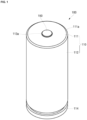
- FIG. 1 is a perspective view illustrating a cylindrical secondary battery 100 according to some embodiments of the present disclosure.
- FIG. 2 is a cross-sectional view illustrating the cylindrical secondary battery 100 in FIG. 1 in the longitudinal direction.
- the cylindrical secondary battery 100 includes a case 110, an electrode assembly 120 accommodated in the case 110, may include a terminal 150 coupled to a terminal hole provided in one end of the case 110, and includes a cap plate 160 which may seal or enclose an opening in the other end of the case 110.
- the case 110 includes a circular upper surface portion 111 and a side surface portion 112 extending downward from the edge of the upper surface portion 111 to a certain length.
- the upper surface portion 111 and the side surface portion 112 of the case 110 may be formed integrally. Additionally, a bent portion 111a bent in a round shape may be further included between the upper surface portion 111 and the side surface portion 112.
- the circular upper surface portion 111 has a flat circular plate shape, and a central portion 113 may protrude in an outward direction away from the electrode assembly 120.
- the central portion 113 may be located at the center of the upper surface portion 111 and is located further outside the case 110 compared to the upper surface portion 111 such that a step may be formed between the central portion 113 and the upper surface portion 111.
- a connection portion 113a connecting an outer edge of the central portion 113 and an inner edge of the upper surface portion 111 may be further included.
- the connection portion 113a may be provided to be inclined due to the step formed between the central portion 113 and the upper surface portion 111.
- the connection portion 113a may connect the central portion 113 and the upper surface portion 111 in a circular ring shape.
- the central portion 113 may have a terminal hole 113b passing through approximately the center thereof.
- the terminal 150 may be insertion-coupled to the terminal hole 113b of the central portion 113.
- the terminal hole 113b may have a circular shape, but is not limited thereto.
- a planar shape of a fastening portion 152 of the terminal 150 may correspond to the shape of a terminal hole 113b. That is, when the terminal hole 113b is circular, the fastening portion 152 of the terminal 150 may have a cylindrical shape. Therefore, when the terminal hole 113b is circular, no separate corners are provided, and thus the terminal hole 113b can be fastened and coupled with the terminal 150 regardless of an angle.
- the second electrode plate 122 is a plate-shaped metal foil made of copper (Cu) or nickel (Ni), of which at least one side is coated with a negative electrode active material such as graphite or carbon. Additionally, the second electrode plate 122 may have a negative electrode uncoated portion that is not coated with the negative electrode active material at a lower end portion thereof. This negative electrode uncoated portion may protrude downward from the electrode assembly 120. That is, the negative electrode uncoated portion of the second electrode plate 122 may protrude further downward compared to the first electrode plate 121 and the separator 123.
- the separator 123 may be polyethylene (PE) or polypropylene (PP), but embodiments according to the present disclosure are not limited thereto.
- the separator prevents or reduces instances of an electrical short between the first electrode plate 121 and the second electrode plate 122 and may only allow the movement of lithium ions.
- a second current collector 140 may have a circular shape corresponding to a lower surface of the electrode assembly 120. An upper surface of the second current collector 140 may be in contact with the lower surface of the electrode assembly 120. The second current collector 140 is fixed and electrically connected to the second electrode plate 122 exposed downward at the electrode assembly 120 by welding while the upper surface thereof is in contact with the lower surface of the electrode assembly 120. Additionally, the second current collector 140 may be brought into contact with and coupled to an inner surface of the beading part 114. Here, the inner surface may be an inner surface of the case 110. The second current collector 140b may be a path for current flow between the second electrode plate 122 of the electrode assembly 120 and the case 110. That is, the case 110 may be a negative terminal.
- the second current collector 140 may be provided with a through hole 141, which passes through between the upper surface and the lower surface, at the center thereof, and the electrolyte may be easily injected into the electrode assembly 120 through the through hole 141.
- the size (diameter) of the through hole 141 may correspond to a core diameter of the electrode assembly 120.
- the terminal 150 may be inserted into the terminal hole 113b of the case 110 and electrically connected to the first current collector 130.
- the terminal 150 may be electrically connected to the first electrode plate 121 of the electrode assembly through the first current collector 130. That is, the terminal 150 may be a positive terminal.
- the terminal 150 and the case 110 may have different polarities.
- the terminal 150 may be formed of a material that is the same as or similar to that of each of the first current collector 130 and the first electrode plate 121.
- the terminal 150 may include a head 151 exposed upward at the case 110 and a fastening portion 152 extending inward of the case 110 from a center of the head 151.
- a planar size of the head 151 may be larger than a planar size of the fastening portion 152. That is, the diameter of the head 151 may be larger than the diameter of the fastening portion 152.
- the upper end of the fastening portion 152 of the terminal 150 may be connected to a lower surface of the head 151, and the head 151 and the fastening portion 152 may be formed integrally.
- the terminal 150 may be coupled to the terminal hole 113b of the case 110 in a direction from the outside to the inside. In this case, the first gasket 116 may be interposed between the terminal 150 and the case 110.
- the terminal 150 may be inserted into the terminal hole 113b of the case 110 in a direction from the outside to the inside and then fixed.
- the terminal 150 may be fixed by a coupling part made of an insulating material, but is not limited thereto.
- a lower surface of the fastening portion 152 may be while in contact with and coupled to an upper surface of the first current collector 130 by welding.
- the fastening portion 152 may protrude further downward compared to a lower surface of the central portion 113 of the case 110.
- the fastening portion 152 may be interposed between the central portion 113 and the first current collector 130.
- An edge area 162 of the cap plate 160 may be fixedly positioned between the beading part 114 and the crimping part 115 of the case 110.
- the cap plate 160 in a state in which the second gasket 118 is positioned under the beading part 114 of the case 110, the cap plate 160 may be mounted below the beading part 114. Afterward, the crimping part 115 of the case 110 is bent in an inward direction of the cap plate 160 and presses the second gasket 118 to couple the cap plate 160 and the case 110.
- the second gasket 118 may be made of a resin material such as polyethylene (PE), polypropylene (PP), or polyethylene terephthalate (PET).
- the second gasket 118 may press and seal a space between the case 110 and the cap plate 160, and may prevent or reduce instances of the cap plate 160 being separated from the case 110.
- An upper portion of the second gasket 118 may be interposed between the beading part 114 and the cap plate 160, and the lower portion may be interposed between the crimping part 115 and the cap plate 160.
- the lower end portion of the second gasket 118 may protrude more toward the center of the cap plate 160 than the crimping part 115.
- the cap plate 160 may include a central area 161 positioned below the through hole 141 of the second current collector 140 and the edge area 162 interposed between the beading part 114 and the crimping part 115 of the case 110 and coupled to the case 110. Additionally, the central area 161 of the cap plate 160 may be in contact with or connected to the second current collector 140. That is, an upper surface of the cap plate 160 may be in contact with a lower surface of the second current collector 140. Accordingly, the cap plate 160 may be formed so that the central area 161 is curved toward the electrode assembly 120 compared to the edge area 162. Additionally, the cap plate 160 further includes a connection area 163 connecting the central area 161 and the edge area 162.
- the central area 161 and the connection area 163 may be concave toward the inside of the case 110 compared to the edge area 162. That is, the edge area 162 of the cap plate 160 may protrude more outward from the case 110 than the central area 161 and the connection area 163. Additionally, the connection area 163 and the edge area 162 may be connected to be inclined due to a step.
- the thickness of the cap plate 160 may be 0.1 to 0.3 times the thickness of the material of the cap plate 160. In this case, a cell rupture pressure range may be 17 to 35 kgf/cm 2 .
- the thickness of the cap plate 160 in the area in which the vent 165 is formed is 0.1 times or more the material thickness of the cap plate 160, it may be easy to perform notch processing or a press process on the cap plate 160. Additionally, when the thickness of the cap plate 160 in the area in which the vent 165 is formed is less than 0.1 times the material thickness of the cap plate 160, deformation or cracks may occur even when the internal pressure of the cylindrical secondary battery 100 does not increase.
- the vent 165 may not rupture even when the internal pressure of the cylindrical secondary battery 100 increases and may not operate as a vent. Additionally, when the thickness of the cap plate 160 in the area in which the vent 165 is formed is 0.3 times or less the material thickness of the cap plate 160, the cap plate 160 may rupture at a desired rupture pressure.
- the cylindrical secondary battery 100 should be tested according to standard specifications to minimize or reduce risks that may occur during transportation by air, land, or ship.
- This test may include tests for altitude, thermal shock, vibrations, impacts, external short circuits, compression/collisions, forced discharge and overcharging.
- an external power supply may be connected to a fully discharged battery to cause over-discharge and induce the reverse polarity of the battery.
- the voltage falls below 0 V and becomes negative. That is, the battery is damaged, no longer provides a voltage, and acts as a resistor, causing a voltage drop. This may cause the battery to heat up and cause a fire or spark.
- the forced discharge test verifies the safety of the battery design at the limits of an appropriate discharge current specification. When the current limit is too high, resulting increase in heat may lead to battery overheating and eventually thermal runaway (fire and/or explosion).
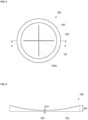
- a vent 165a may be provided in the central area 161 of the cap plate 160.
- the central area 161 may be a circular (in a plan view) area with a size corresponding to the core diameter of the electrode assembly 120 from the center of the cap plate 160.
- the vent 165a may correspond to the circular central area 161 and have a circular ring shape formed along the circumference of the central area 161 in a plan view.
- the area of the ring-shaped vent 165a may be determined based on the core diameter a of the electrode assembly 120. That is, an inner diameter c of the ring shape of the vent 165a may vary in proportion to the core diameter a of the electrode assembly 120.
- the two vents 165c may be formed in linear lines spaced apart from each other based on the central area 161.
- the three vents 165c may be formed into linear vents spaced apart from each other.
- the three vents 165c may be formed into three linear lines spaced apart from each other based on the central area 161 and the spacing between the linear lines is uniform.
- a rupture may occur in at least one of the plurality of vents.
- the spacing between the vents may be the same.
- the length of a long portion may be about 1 to 10 times the length of a relatively short portion (i.e., a relatively short linear-shaped vent).
- the length of the short portion i.e., a relatively short linear-shaped vent
- the length of the relatively long portion may be about 0.1 to 1 times the length of the relatively long portion (i.e., a relatively long linear-shaped vent).
- the thickness of the cap plate 160 in the area in which the vent 165c is formed may be different.
- the thickness of the cap plate 160 in the area in which the vent 165c is formed may be 0.1 to 0.3 times the material thickness of the cap plate 160.
- the cell rupture pressure range may be 17 to 35 kgf/cm 2 .
- the thickness of the cap plate 160 in the area in which a relatively long linear portion (i.e., a long linear-shaped vent) of the vent 165c is formed may be relatively small (e.g., may be about 0.1 times the thickness of the cap plate material).
- the thickness of the cap plate 160 in the area in which a relatively short linear portion (i.e., a short linear-shaped vent) of the vent 165c is formed may be relatively large (e.g., may be about 0.3 times the thickness of the cap plate material). That is, a notch depth may be increased for the relatively long linear part to be easily vented, and the notch depth may be decreased for the relatively short linear part.
- the vents 165d and 165e may have a spiral shape and a pinwheel shape extending from the central area 161 respectively in a plan view.
- the vents 165d and 165e may be located in both the connection area 163 and the central area 161 of the cap plate 160.
- adistance from a start point to an end point of each of the spiral and pinwheel-shaped vents 165d and 165e may be 0.5 to 5.5 times the core diameter a of the electrode assembly 120.
- the spiral-shaped vent 165d may have a spiral shape extending from a start point in the central area 161 to an end point in the connection area 163. That is, the spiral-shaped vent 165d may have a shape in which the radius of a spiral line increases in a plan view.
- the thickness of the cap plate 160 may be uniform in the area in which the spiral-shaped vent 165d is formed. As described above, the thickness of the cap plate 160 in the area in which the vent 165d is formed may be 0.1 to 0.3 times the thickness of the material of the cap plate 160. In this case, the cell rupture pressure range may be 17 to 35 kgf/cm 2 .
- the thickness of the cap plate 160 in the area in which the spiral-shaped vent 165d is formed may increase in an extending direction from the center thereof. Therefore, by varying the thickness of the cap plate 160 in the area in which the vent 165d is formed for each location, the venting area may be adjusted when a problem occurs inside the cell.
- the thickest thickness of the cap plate 160 may be 0.3 times the material thickness of the cap plate 160.
- the cell rupture pressure range may be 35 kgf/cm 2 .
- the thinnest thickness of the cap plate 160 in the area in which the spiral-shaped vent 165d is formed may be 0.1 times the material thickness of the cap plate 160. In this case, the cell rupture pressure range may be 17 kgf/cm2
- the vent 165e may have a pinwheel shape in which a plurality of circular arcs with the same radius are arranged at equal intervals based on the center of the central axis (rotation axis) within the circular vent.
- a thickness of the cap plate 160 may increase in an extending direction from the center. That is, when the internal pressure increases after venting along the initial arc of the pinwheel-shaped vent 165e, the entire vent 165e including an extended portion of a circular vent 165e formed along the planar perimeter of the cap plate 160 may be vented.
- the thickest thickness of the cap plate 160 may be 0.25 to 0.3 times the material thickness of the cap plate 160.
- the cell rupture pressure may be 35 kgf/cm 2 .
- the smallest thickness of the cap plate 160 in the area in which the pinwheel-shaped vent 165e is formed may be 0.1 to 0.15 times the material thickness of the cap plate 160. In this case, the cell rupture pressure may be 17 kgf/cm 2 .
- a vent and jelly roll structure is designed to satisfy a forced discharge item of the standard specifications to suppress heat generation and prevent or reduce ignition during forced discharge evaluation.
- heat generation can be suppressed by forming a vent structure in which pressure is gradually released so that venting proceeds gradually.
- a cylindrical secondary battery according to some embodiments of the present disclosure is provided with both a negative electrode and a positive electrode at one side, when a plurality of cylindrical secondary batteries are electrically connected through a bus bar, the bus bar connection structure can be simplified by allowing connection only at the one side.
- the vent (165, 165a, 165b, 165c, 165d, 165e) has the pinwheel shape in which a plurality of circular arcs with constant radii are arranged at equal intervals based on a center of the cap plate (160).
Landscapes
- Chemical & Material Sciences (AREA)
- Chemical Kinetics & Catalysis (AREA)
- Electrochemistry (AREA)
- General Chemical & Material Sciences (AREA)
- Inorganic Chemistry (AREA)
- Engineering & Computer Science (AREA)
- Manufacturing & Machinery (AREA)
- Sealing Battery Cases Or Jackets (AREA)
Applications Claiming Priority (1)
| Application Number | Priority Date | Filing Date | Title |
|---|---|---|---|
| KR1020230115069A KR20250032347A (ko) | 2023-08-31 | 2023-08-31 | 원통형 이차 전지 |
Publications (1)
| Publication Number | Publication Date |
|---|---|
| EP4517894A1 true EP4517894A1 (de) | 2025-03-05 |
Family
ID=92209082
Family Applications (1)
| Application Number | Title | Priority Date | Filing Date |
|---|---|---|---|
| EP24192224.4A Pending EP4517894A1 (de) | 2023-08-31 | 2024-08-01 | Zylindrische sekundärbatterie |
Country Status (4)
| Country | Link |
|---|---|
| US (1) | US20250079623A1 (de) |
| EP (1) | EP4517894A1 (de) |
| KR (1) | KR20250032347A (de) |
| CN (1) | CN119542665A (de) |
Cited By (2)
| Publication number | Priority date | Publication date | Assignee | Title |
|---|---|---|---|---|
| EP4593137A1 (de) * | 2024-01-23 | 2025-07-30 | Samsung SDI Co., Ltd. | Zylindrische sekundärbatterie |
| EP4597656A1 (de) * | 2024-01-31 | 2025-08-06 | Samsung Sdi Co., Ltd. | Zylindrische sekundärbatterie |
Citations (4)
| Publication number | Priority date | Publication date | Assignee | Title |
|---|---|---|---|---|
| US20230113374A1 (en) * | 2021-10-12 | 2023-04-13 | Lg Energy Solution, Ltd. | Battery pack and vehicle including the same |
| CN116014313A (zh) * | 2021-10-22 | 2023-04-25 | 株式会社Lg新能源 | 圆筒形电池、包括它的电池组及汽车 |
| KR102570308B1 (ko) * | 2022-10-27 | 2023-08-24 | 삼성에스디아이 주식회사 | 원통형 이차 전지 |
| EP4354605A1 (de) * | 2022-10-11 | 2024-04-17 | Samsung SDI Co., Ltd. | Zylindrische sekundärbatterie |
-
2023
- 2023-08-31 KR KR1020230115069A patent/KR20250032347A/ko not_active Ceased
-
2024
- 2024-05-08 US US18/658,865 patent/US20250079623A1/en active Pending
- 2024-08-01 EP EP24192224.4A patent/EP4517894A1/de active Pending
- 2024-08-19 CN CN202411136185.9A patent/CN119542665A/zh active Pending
Patent Citations (4)
| Publication number | Priority date | Publication date | Assignee | Title |
|---|---|---|---|---|
| US20230113374A1 (en) * | 2021-10-12 | 2023-04-13 | Lg Energy Solution, Ltd. | Battery pack and vehicle including the same |
| CN116014313A (zh) * | 2021-10-22 | 2023-04-25 | 株式会社Lg新能源 | 圆筒形电池、包括它的电池组及汽车 |
| EP4354605A1 (de) * | 2022-10-11 | 2024-04-17 | Samsung SDI Co., Ltd. | Zylindrische sekundärbatterie |
| KR102570308B1 (ko) * | 2022-10-27 | 2023-08-24 | 삼성에스디아이 주식회사 | 원통형 이차 전지 |
Cited By (2)
| Publication number | Priority date | Publication date | Assignee | Title |
|---|---|---|---|---|
| EP4593137A1 (de) * | 2024-01-23 | 2025-07-30 | Samsung SDI Co., Ltd. | Zylindrische sekundärbatterie |
| EP4597656A1 (de) * | 2024-01-31 | 2025-08-06 | Samsung Sdi Co., Ltd. | Zylindrische sekundärbatterie |
Also Published As
| Publication number | Publication date |
|---|---|
| CN119542665A (zh) | 2025-02-28 |
| KR20250032347A (ko) | 2025-03-07 |
| US20250079623A1 (en) | 2025-03-06 |
Similar Documents
| Publication | Publication Date | Title |
|---|---|---|
| US12176568B2 (en) | Cylindrical lithium ion secondary battery | |
| EP4439748A1 (de) | Sekundärbatterie | |
| US20240097291A1 (en) | Cylindrical lithium ion secondary battery | |
| US9118071B2 (en) | Rechargeable battery | |
| US8877369B2 (en) | Secondary battery having current collectors with deformable portions underneath a vent | |
| US9203060B2 (en) | Secondary battery | |
| US20150236334A1 (en) | Cap assembly and secondary battery including the same | |
| US20250079623A1 (en) | Cylindrical secondary battery | |
| US7919206B2 (en) | Electrode assembly and secondary battery using the same | |
| EP4216345A1 (de) | Sekundärbatterie | |
| JP5203729B2 (ja) | 二次電池及び電池モジュール | |
| EP2325924A1 (de) | Sekundärbatterie mit Kurzschlussvorrichtung | |
| EP4117096A1 (de) | Sekundärbatterie | |
| US20230207989A1 (en) | Cap Assembly and Secondary Battery Including the Same | |
| EP4362178A1 (de) | Zylindrische sekundärbatterie | |
| US11664523B2 (en) | Secondary battery | |
| EP4235929B1 (de) | Sekundärbatterie | |
| KR102522701B1 (ko) | 이차 전지 | |
| US9608257B2 (en) | Rechargeable battery having upper cover | |
| US20240178509A1 (en) | Secondary battery | |
| US12476310B2 (en) | Secondary battery and manufacturing method of secondary battery | |
| EP4451435A2 (de) | Sekundärbatterie | |
| US20230335836A1 (en) | Secondary battery | |
| US20260031495A1 (en) | Secondary battery and method of manufacturing same | |
| US20250149740A1 (en) | Secondary battery |
Legal Events
| Date | Code | Title | Description |
|---|---|---|---|
| PUAI | Public reference made under article 153(3) epc to a published international application that has entered the european phase |
Free format text: ORIGINAL CODE: 0009012 |
|
| STAA | Information on the status of an ep patent application or granted ep patent |
Free format text: STATUS: REQUEST FOR EXAMINATION WAS MADE |
|
| 17P | Request for examination filed |
Effective date: 20240801 |
|
| AK | Designated contracting states |
Kind code of ref document: A1 Designated state(s): AL AT BE BG CH CY CZ DE DK EE ES FI FR GB GR HR HU IE IS IT LI LT LU LV MC ME MK MT NL NO PL PT RO RS SE SI SK SM TR |