EP4354625A1 - Batterie secondaire et module de batterie la comprenant - Google Patents
Batterie secondaire et module de batterie la comprenant Download PDFInfo
- Publication number
- EP4354625A1 EP4354625A1 EP22907982.7A EP22907982A EP4354625A1 EP 4354625 A1 EP4354625 A1 EP 4354625A1 EP 22907982 A EP22907982 A EP 22907982A EP 4354625 A1 EP4354625 A1 EP 4354625A1
- Authority
- EP
- European Patent Office
- Prior art keywords
- battery
- safety vent
- secondary battery
- conductive wire
- electrode
- Prior art date
- Legal status (The legal status is an assumption and is not a legal conclusion. Google has not performed a legal analysis and makes no representation as to the accuracy of the status listed.)
- Pending
Links
Images


Classifications
-
- H—ELECTRICITY
- H01—ELECTRIC ELEMENTS
- H01M—PROCESSES OR MEANS, e.g. BATTERIES, FOR THE DIRECT CONVERSION OF CHEMICAL ENERGY INTO ELECTRICAL ENERGY
- H01M50/00—Constructional details or processes of manufacture of the non-active parts of electrochemical cells other than fuel cells, e.g. hybrid cells
- H01M50/50—Current conducting connections for cells or batteries
- H01M50/572—Means for preventing undesired use or discharge
- H01M50/574—Devices or arrangements for the interruption of current
- H01M50/578—Devices or arrangements for the interruption of current in response to pressure
-
- H—ELECTRICITY
- H01—ELECTRIC ELEMENTS
- H01M—PROCESSES OR MEANS, e.g. BATTERIES, FOR THE DIRECT CONVERSION OF CHEMICAL ENERGY INTO ELECTRICAL ENERGY
- H01M50/00—Constructional details or processes of manufacture of the non-active parts of electrochemical cells other than fuel cells, e.g. hybrid cells
- H01M50/10—Primary casings; Jackets or wrappings
- H01M50/147—Lids or covers
- H01M50/148—Lids or covers characterised by their shape
- H01M50/152—Lids or covers characterised by their shape for cells having curved cross-section, e.g. round or elliptic
-
- H—ELECTRICITY
- H01—ELECTRIC ELEMENTS
- H01M—PROCESSES OR MEANS, e.g. BATTERIES, FOR THE DIRECT CONVERSION OF CHEMICAL ENERGY INTO ELECTRICAL ENERGY
- H01M50/00—Constructional details or processes of manufacture of the non-active parts of electrochemical cells other than fuel cells, e.g. hybrid cells
- H01M50/10—Primary casings; Jackets or wrappings
- H01M50/147—Lids or covers
- H01M50/166—Lids or covers characterised by the methods of assembling casings with lids
- H01M50/167—Lids or covers characterised by the methods of assembling casings with lids by crimping
-
- H—ELECTRICITY
- H01—ELECTRIC ELEMENTS
- H01M—PROCESSES OR MEANS, e.g. BATTERIES, FOR THE DIRECT CONVERSION OF CHEMICAL ENERGY INTO ELECTRICAL ENERGY
- H01M50/00—Constructional details or processes of manufacture of the non-active parts of electrochemical cells other than fuel cells, e.g. hybrid cells
- H01M50/10—Primary casings; Jackets or wrappings
- H01M50/183—Sealing members
- H01M50/186—Sealing members characterised by the disposition of the sealing members
-
- H—ELECTRICITY
- H01—ELECTRIC ELEMENTS
- H01M—PROCESSES OR MEANS, e.g. BATTERIES, FOR THE DIRECT CONVERSION OF CHEMICAL ENERGY INTO ELECTRICAL ENERGY
- H01M50/00—Constructional details or processes of manufacture of the non-active parts of electrochemical cells other than fuel cells, e.g. hybrid cells
- H01M50/30—Arrangements for facilitating escape of gases
- H01M50/308—Detachable arrangements, e.g. detachable vent plugs or plug systems
-
- H—ELECTRICITY
- H01—ELECTRIC ELEMENTS
- H01M—PROCESSES OR MEANS, e.g. BATTERIES, FOR THE DIRECT CONVERSION OF CHEMICAL ENERGY INTO ELECTRICAL ENERGY
- H01M50/00—Constructional details or processes of manufacture of the non-active parts of electrochemical cells other than fuel cells, e.g. hybrid cells
- H01M50/30—Arrangements for facilitating escape of gases
- H01M50/342—Non-re-sealable arrangements
- H01M50/3425—Non-re-sealable arrangements in the form of rupturable membranes or weakened parts, e.g. pierced with the aid of a sharp member
-
- H—ELECTRICITY
- H01—ELECTRIC ELEMENTS
- H01M—PROCESSES OR MEANS, e.g. BATTERIES, FOR THE DIRECT CONVERSION OF CHEMICAL ENERGY INTO ELECTRICAL ENERGY
- H01M2200/00—Safety devices for primary or secondary batteries
- H01M2200/20—Pressure-sensitive devices
-
- H—ELECTRICITY
- H01—ELECTRIC ELEMENTS
- H01M—PROCESSES OR MEANS, e.g. BATTERIES, FOR THE DIRECT CONVERSION OF CHEMICAL ENERGY INTO ELECTRICAL ENERGY
- H01M50/00—Constructional details or processes of manufacture of the non-active parts of electrochemical cells other than fuel cells, e.g. hybrid cells
- H01M50/10—Primary casings; Jackets or wrappings
- H01M50/102—Primary casings; Jackets or wrappings characterised by their shape or physical structure
- H01M50/107—Primary casings; Jackets or wrappings characterised by their shape or physical structure having curved cross-section, e.g. round or elliptic
-
- Y—GENERAL TAGGING OF NEW TECHNOLOGICAL DEVELOPMENTS; GENERAL TAGGING OF CROSS-SECTIONAL TECHNOLOGIES SPANNING OVER SEVERAL SECTIONS OF THE IPC; TECHNICAL SUBJECTS COVERED BY FORMER USPC CROSS-REFERENCE ART COLLECTIONS [XRACs] AND DIGESTS
- Y02—TECHNOLOGIES OR APPLICATIONS FOR MITIGATION OR ADAPTATION AGAINST CLIMATE CHANGE
- Y02E—REDUCTION OF GREENHOUSE GAS [GHG] EMISSIONS, RELATED TO ENERGY GENERATION, TRANSMISSION OR DISTRIBUTION
- Y02E60/00—Enabling technologies; Technologies with a potential or indirect contribution to GHG emissions mitigation
- Y02E60/10—Energy storage using batteries
Definitions
- the present disclosure relates to a secondary battery and a battery module including the same, and more particularly, to a secondary battery with enhanced safety and space utilization, and a battery module including the same.
- the demand for the lithium secondary battery such as a lithium ion battery or a lithium ion polymer battery, which have advantages such as a high energy density, a discharge voltage, an output stability, and the like is high.
- the secondary battery may be classified on the basis of the structure of an electrode assembly having a structure in which a cathode and an anode are stacked with a separator being interposed therebetween.
- an electrode assembly having a structure in which a cathode and an anode are stacked with a separator being interposed therebetween.
- a jelly-roll type electrode assembly having a structure in which long sheets of cathodes and anodes are wound in the state in which a separator is interposed therebetween
- a stacked type electrode assembly having a structure in which pluralities of cathodes and anodes, cut by a certain size unit, are sequentially stacked in the state in which separators are interposed therebetween, or the like.
- a stacked/folded type electrode assembly which is a combination of the jelly-roll type electrode assembly and the stacked type electrode assembly, having a structure in which unit cells stacked with predetermined units of the cathodes and the anodes are sequentially wound with a separator being interposed therebetween in the state of having been placed on a separation film.
- the secondary battery is classified into a cylindrical battery where an electrode assembly is mounted in a cylindrical case, a prismatic battery where an electrode assembly is mounted in a prismatic can, and a pouch type battery where an electrode assembly is mounted in a pouch type case of an aluminum laminate sheet.
- a secondary battery should satisfy performance suitable for the intended use and at the same time, has safety, thereby capable of being suitably used in the market.
- the design factors are determined in consideration of these performance and safety aspects at the same time. Batteries whose design and manufacturing have been completed are subjected to performance evaluations such as lifespan, high rate characteristics, and high/low temperature characteristics, as well as to safety evaluations such as overcharge, over-discharge, impact, nail test, and hot box.
- CID Current Interrupt Device
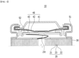
- Fig. 1 is a partial cross-sectional view showing a cross section of an upper part of a conventional cylindrical secondary battery.
- an electrode assembly 20 is housed in a cylindrical can 30, and a cap assembly 40 is mounted on the opened upper part of the cylindrical can 30, thereby capable of manufacturing a cylindrical secondary battery 10.
- the electrode assembly 20 may be a jelly-roll type electrode assembly in which a first electrode 21, a second electrode 22 and a separator 23 are rolled.
- the cap assembly 40 may include an upper end cap 41, a safety vent 42 for lowering an internal pressure, and a CID (current interruption device) filter 43.
- the upper end cap 41 and the safety vent 42 may form a structure closely attached to each other, and the safety vent 42 may be connected to a central part of the CID filter 43.
- a first electrode tab 21t protruding from the first electrode 21 may be connected to a lower end part of the CID filter 43.
- the first electrode 21 may be a cathode
- the first electrode tab 21t may be a cathode tab.
- the upper end cap 41, the safety vent 42, the CID filter 43, and the first electrode tab 21t are sequentially connected, so that the upper end cap 41 can be electrically connected to the electrode assembly 20, and can function as an electrode terminal.
- a gasket 51 for sealing between the cap assembly 40 and the cylindrical can 30 and a CID gasket 52 surrounding an edge of the CID filter 43 can be arranged.
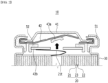
- Fig. 2 is a partial cross-sectional view showing a state of the cylindrical secondary battery of Fig. 1 when an internal pressure rises.
- the cylindrical secondary battery 10 when the cylindrical secondary battery 10 is exposed to high temperatures or is placed in an abnormal operating state, gas is generated and the internal pressure rises, the shape of the safety vent 42 is reversed, and the CID filter 43 is separated to interrupt the current.
- the CID filter 43 is divided into a part 43a connected to the safety vent 42 and a part 43b connected to the first electrode tab 21t, and a current flow between the upper end cap 41 serving as an electrode terminal and the first electrode tab 21t is interrupted.
- the notch part of the safety vent 42 is interrupted, the safety vent 42 is opened, and the internal gas is discharged.
- the structural strength is excellent, but when the safety vent 42 is opened and the internal gas is discharged, there is a drawback that spatial portion is degraded by the upper end cap 41, and the safety vent 42 is fully opened, thus limiting gas discharge.
- the CID filter 43 cannot be reliably separated, and current continues to flow even in an abnormal operating state.
- the present disclosure is made to solve the above-mentioned problems, and an object of the present disclosure is to provide a secondary battery that can reliably interrupt the flow of current in an abnormal operating state while improving space utilization and increasing battery capacity by eliminating internal parts, and a battery module including the same.
- a secondary battery comprising: an electrode assembly which comprises electrodes and a separator; a battery can which houses the electrode assembly and has an opened upper part; and a safety vent which is coupled to the open upper part of the battery can, wherein the electrode assembly comprises an electrode tab protruding from one of the electrodes in a direction in which the safety vent is located, wherein the safety vent is formed with a notch part extending along the peripheral direction, wherein the safety vent comprises a central part positioned inside the notch part and an outer peripheral part positioned outside the notch part, and wherein the electrode tab is attached to a lower surface of the outer peripheral part.
- the notch part may be in the form of a groove having a thickness less than that of an adjacent region.
- the safety vent may be exposed to the outside at the upper end.
- a first external conductive wire for connection with an external electrical component may be attached to the upper surface of the central part.
- the secondary battery may further comprise a gasket positioned between the battery can and the safety vent, wherein an upper end of the battery can is crimped and joined while being bent in a direction where the gasket is positioned, so that a crimping part can be formed in the battery can.
- the safety vent may comprise a curling part formed by bending an outermost region of the outer peripheral part, and the gasket may surround the curling part.
- the gasket may be positioned between the crimping part and the curling part.
- the safety vent may comprise a bent part formed by bending a portion of the outer peripheral portion in an upward direction.
- the thickness of the notch part may be 5% or more and 50% or less of the thickness of the safety vent.
- a battery module comprising: the secondary batteries; and a first external conductive wire and a second external conductive wire which electrically connect the secondary batteries, wherein the first external conductive wire is attached to the upper surface of the central part, and the second external conductive wire is attached to the battery can.
- the battery can and the safety vent are crimped and joined to form a crimping part in the battery can, and the second external conductive wire may be joined to the crimping part.
- the parts of the upper end cap and the CID filter are eliminated, thereby being able to increase space utilization and increase battery capacity by the amount of the eliminated parts.
- planar it means when a target portion is viewed from the upper side
- cross-sectional it means when a target portion is viewed from the side of a cross section cut vertically.
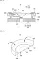
- Fig. 3 is an exploded perspective view of a secondary battery according to one embodiment of the present disclosure.
- Fig. 4 is a partial cross-sectional view showing a cross section of an upper part of a secondary battery according to one embodiment of the present disclosure.
- Fig. 4 may be a cross-section of an upper part of the secondary battery of Fig. 3 cut along an xz plane after being assembled.
- the secondary battery 100 includes an electrode assembly 200, a battery can 300 which houses the electrode assembly 200 and has an opened upper part; and a safety vent 400 which is coupled to the opened upper part of the battery can 300.
- the electrode assembly 200 may include electrodes 210 and 220 and a separator 230. More specifically, the electrode assembly 200 may include a first electrode 210, a second electrode 220 and a separator 230. The first electrode 210, the second electrode 220, and the separator 230 can be rolled together to form a jelly-roll type electrode assembly 200. The separator 230 may be interposed between the first electrode 210 and the second electrode 220. In addition, in order to prevent the first electrode 210 and the second electrode 220 from contacting with each other when they are rolled in the form of a jelly roll, it is preferred that a separator 230 is further arranged.
- the first electrode 210 may be formed by applying an electrode active material onto the first electrode current collector.
- an electrode tab 210t may be attached by a method such as welding.
- the second electrode 220 may be formed by applying an electrode active material onto the second electrode current collector. In a portion of the second electrode current collector where the electrode active material is not applied and the second electrode current collector is exposed, another electrode tab 220t may be attached by a method such as welding.
- the first electrode 210 may be a cathode
- the second electrode 220 may be an anode
- the electrode tab 210t may be a cathode tab
- another electrode tab 220t may be an anode tab
- the electrode tabs 210t and 220t may be protruded in mutually opposite directions. That is, the electrode assembly 200 includes an electrode tab 210t protruding from one of the electrodes 210 and 220 in the direction where the safety vent 400 is positioned, and an electrode tab 220t protruding from the other one of the electrodes 210 and 220 in a direction where the bottom part of the battery can 300 is positioned.
- the electrode tab 210t may be connected to the safety vent 400
- the other electrode tab 220t may be connected to the bottom part of the battery can 300.
- the safety vent 400 and the battery can 300 can each function as electrode terminals of the secondary battery 100.
- the battery can 300 is a structure for housing the electrode assembly 200 impregnated with an electrolyte solution, which may include a metal material and may be a cylindrical can.
- Fig. 5 is a cross-sectional perspective view of a safety vent included in the secondary battery of Fig. 3 .
- Fig. 6 is a partial view which enlarges and shows a section A of Fig. 4 .
- the safety vent in Fig. 5 is shown in a cross-sectional perspective view cut in half for convenience of illustration.
- the safety vent 400 may be formed with a notch part 400N extending along the peripheral direction, and the safety vent 400 includes a central part 410 positioned inside the notch part 400N and an outer peripheral part 420 positioned outside the notch part 400N. That is, in the safety vent 400, the central part 410 and the outer peripheral part 420 may be divided by a notch part 400N as boundary extending along the peripheral direction.
- This notch part 400N is in the form of a groove having a thickness less than the adjacent region. As an example, a state in which a V-shaped groove is formed on the lower surface of the safety vent 400 is illustrated.
- the electrode tab 210t protruding from the electrode assembly 200 in the direction where the safety vent 400 is positioned is attached to a lower surface of the outer peripheral part 420 of the safety vent 400.
- the attachment method between the electrode tab 210t and the outer peripheral part 420 is not particularly limited as long as electrical connection is possible, but welding can be applied as an example.
- the safety vent 400 according to the present embodiment may be exposed to the outside at the upper end.
- the safety vent 400 according to the present embodiment has a structure in which the upper end cap is eliminated, and may be arranged on the uppermost side and exposed to the outside.
- the safety vent 400 instead of the upper end cap functions as an electrode terminal. That is, as described above, the electrode tabs 210t are attached to the safety vent 400 and connected to each other, the safety vent 400 is exposed to the outside from the upper end, and a first external conductive wire for connection with an external electrical component may be attached to the upper surface of the safety vent 400.
- the safety vent 400 can function as an electrode terminal for guiding the current flow of the electrode assembly 200.
- a first external conductive wire for connection with an external electrical component may be attached to the upper surface of the central part 410 of the safety vent 400.
- the electrode tab 210t and the first external conductive wire can be attached to regions that are distinguished from each other in the safety vent 400, in such a manner that the electrode tab 210t is attached to the outer peripheral part 420 and the first external conductive wire is attached to the central part 410.
- the safety vent 400 may interrupt current in an abnormal operating state of the secondary battery 100. This will be described again below with reference to Figs. 7 and 8 .
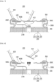
- Fig. 7 is a partial cross-sectional view showing a state in which a first external conductive wire and a second external conductive wire are attached to the secondary battery of Fig. 3 .
- a state in which a first external conductive wire 610 for connection with an external electrical component is attached to an upper surface of the central part 410 of the safety vent 400 is illustrated.
- a second external conductive wire 620 for connection with other external electrical components may be attached to the battery can 300.
- the first external conductive wire 610 and the second external conductive wire 620 may include an electrically connectable metal material, and a welding method can be applied to both the attachment between the first external conductive wire 610 and the central part 410 and the attachment between the second external conductive wire 620 and the battery can 300.
- the electrode tab 210t is connected to the safety vent 400, and another electrode tab 220t may be connected to the bottom part of the battery can 300.
- the safety vent 400 and the battery can 300 each function as electrode terminals of the secondary battery 100, so that the first external conductive wire 610 and the second external conductive wire 620 can be attached thereto.
- the electrode tab 210t may be a cathode tab, and another electrode tab 220t may be an anode tab.
- the safety vent 400 can function as a cathode terminal
- the battery can 300 may function as an anode terminal.
- the external electrical component connected to the opposite side of the first external conductive wire 610 or the second external conductive wire 620 may be another secondary battery or an electric component requiring power supply.
- the battery module according to the present embodiment includes secondary batteries 100 according to the present embodiment, and a first external conductive wire 610 and a second external conductive wire 620 which electrically connect the secondary batteries 100.
- the first external conductive wire 610 is attached to the upper surface of the central part 410 and the second external conductive wire 620 is attached to the battery can 300.
- the secondary batteries 100 according to the present embodiment are gathered to form a battery module, and the respective secondary batteries 100 may be connected to each other in series or in parallel through the first external conductive wire 610 and the second external conductive wire 620.
- Fig. 8 is a partial cross-sectional view showing the state of the secondary battery of Fig. 7 when the internal pressure rises.
- Fig. 8 when the secondary battery 100 is placed in an abnormal operating state such as overcharging or external short circuit, gas is rapidly generated inside the secondary battery 100 to increase internal pressure.
- the shape of the safety vent 400 is reversed by the increased internal pressure P, and eventually the notch part 400N having low strength due to its thin thickness may be torn off.
- the outer peripheral part 420 to which the electrode tab 210t is connected and the central part 410 to which the first external conductive wire 610 is connected are completely separated from each other.
- the current can be interrupted in the same manner as above. An attempt was made to improve the safety of the secondary battery 100 by preventing the secondary battery 100 from leading to explosion due to continued heat generation.
- the secondary battery 100 Compared with the conventional secondary battery 10 shown in Figs. 1 and 2 , the secondary battery 100 according to the present embodiment has a form in which the upper end cap 41 and the CID filter 43 are eliminated.
- This secondary battery has the advantage that by removing the upper end cap and the CID filter parts, the space utilization can be improved and the battery capacity can be increased by the space of the removed parts.
- the safety vent 400 can be distinguished from the portion to which the electrode tab 210t is attached and the portion to which the first external conductive wire 610 is attached, with the notch part 400N serving as a boundary, the current flow can be effectively interrupted in abnormal operating state, even without the upper end cap and the CID filter.
- the notch part 400N is cut or torn and the safety vent 400 is opened, so that internal gas is discharged.
- the safety vent 400 is exposed to the outside at the upper end without an upper end cap, and therefore, the shape reversal or separation of the safety vent 400 when the pressure resistance rises can be freely performed without being hindered.
- the thickness T1 of the notch part 400N may be 5% or more and 50% or less of the thickness T2 of the safety vent 400.
- the notch part 400N may be in the form of a groove having a thickness less than the adjacent region, and the thickness T1 of the notch part 400N may be 5% or more and 50% or less of the thickness T2 of other regions of the safety vent 400 other than the region where the notch part 400N is formed.
- the thickness T1 of the notch part 400N is less than 5% of the thickness T2 of the safety vent 400, it may help to completely break the notch part 400N when the internal pressure rises.
- the thickness T1 of the notch part 400N is excessively thin, cracks may occur due to impact during assembly or installation of the secondary battery 100 or a battery module including the same. That is, there may be a problem that a crack is formed in advance in the notch part 400N before the internal pressure rises in an abnormal operation state. Under internal pressure rise situation, the notch part 400N is not completely broken due to the pre-generated cracks, which causes a problem that the current is not cut off.
- the thickness T1 of the notch part 400N exceeds 50% of the thickness T2 of the safety vent 400, the thickness T1 of the notch part 400N is excessively thick, and thus, the notch part 400N may not be completely broken even if the internal pressure rises due to an abnormal operating state.
- the notch part 400N is not completely broken, similarly, the central part 410 and the outer peripheral part 420 are not completely separated, and thus, current is not interrupted.
- the safety vent 400 is coupled to the opened upper part of the battery can 300 to seal the electrode assembly 200 and the electrolyte contained in the battery can 300.
- the battery can 300 and the safety vent 400 may be crimped and joined.
- the secondary battery 100 according to the present embodiment may further include a gasket 500 positioned between the battery can 300 and the safety vent 400, and an upper end of the battery can 300 is crimped and joined while being bent in the direction where the gasket 500 is located, so that a crimping part 300C may be formed in the battery can 300. That is, the gasket 500 may surround the safety vent 400 and the crimping part 300C of the bent battery can 300 may surround the gasket 500.
- the gasket 500 may interrupt electrical connection between the battery can 300 and the safety vent 400 while increasing sealing force between the crimping part 300C and the safety vent 400.
- the gasket 500 may include an electrically insulating material. Examples thereof include one or more materials selected from the group consisting of polypropylene (PP), polyethylene terephthalate (PET), polybutylene terephthalate (PBT) and perfluoroalkoxy alkane (PFA).
- PP polypropylene
- PET polyethylene terephthalate
- PBT polybutylene terephthalate
- PFA perfluoroalkoxy alkane
- the safety vent 400 may be formed with a bent part 400B.
- the safety vent 400 may include a bent part 400B formed by bending a portion of the outer peripheral part 420 in an upward direction.
- the notch part 400N of the safety vent 400 is broken and separated into a central part 410 and an outer peripheral part 420.
- the flow of current is interrupted, but a certain amount of space is preferably formed between the central part 410 of the safety vent 400 and the electrode tab 210t in order to reliably interrupt the current.
- a bent part 400B bent in an upward direction may be formed in order to increase the distance between the central part 410 and the electrode tab 210t.
- a curling part 400C may be provided at a portion corresponding to the crimping part 300C in the safety vent 400.
- the safety vent 400 may include a curling part 400C formed by bending the outermost region of the outer peripheral part 420, and the gasket 500 may surround the curling part 400C.
- Figs. 3 and 5 show the state of the flange part 400F before the curling part 400C is formed, and Fig 4 shows a state in which the flange part 400F is bent inward to form the curling part 400C.
- the crimping part 300C of the battery can 300 may surround the safety vent 400 with the gasket 500 being interposed therebetween.
- crimping joint may be performed while surrounding the curling part 400C of the safety vent 400. That is, the gasket 500 may be positioned between the crimping part 300C and the curling part 400C.
- the central part 410 of the safety vent 400 is made of one layer, but the curling part 400C of the outer peripheral part 420 surrounded by the crimping part 300C may be made of two layers. That is, by providing the curling part 400C, an attempt was made to prevent damage to the safety vent 400 that may occur during crimping joint and at the same time, not interfere with the shape reversal or separation of the safety vent 400 when the internal pressure rises.
- the second external conductive wire 620 may be joined to the crimping part 300C of the battery can 300.
- the second external conductive wire 620 may be joined to another region of the battery can 300, but the second external conductive wire 620 is preferably joined to the crimping part 300C in order to shorten the current path between the cathode and the anode and thus reduce the total resistance of the battery module.
- the secondary battery or the battery module according to embodiments of the present disclosure described above can be mounted together with various control and protection systems such as BMS (Battery Management System), BDU (Battery Disconnect Unit), and a cooling system to form a battery pack.
- BMS Battery Management System
- BDU Battery Disconnect Unit
- a cooling system to form a battery pack.
- the secondary battery, the battery module or the battery pack can be applied to various devices.
- vehicle means such as an electric bike, an electric vehicle and a hybrid electric vehicle, or ESS(Energy Storage System), and can be applied to various devices capable of using a secondary battery, without being limited thereto.
Landscapes
- Chemical & Material Sciences (AREA)
- Chemical Kinetics & Catalysis (AREA)
- Electrochemistry (AREA)
- General Chemical & Material Sciences (AREA)
- Connection Of Batteries Or Terminals (AREA)
- Gas Exhaust Devices For Batteries (AREA)
- Sealing Battery Cases Or Jackets (AREA)
Applications Claiming Priority (3)
| Application Number | Priority Date | Filing Date | Title |
|---|---|---|---|
| KR20210180019 | 2021-12-15 | ||
| KR1020220170293A KR102867399B1 (ko) | 2021-12-15 | 2022-12-08 | 이차 전지 및 이를 포함하는 전지 모듈 |
| PCT/KR2022/020510 WO2023113515A1 (fr) | 2021-12-15 | 2022-12-15 | Batterie secondaire et module de batterie la comprenant |
Publications (2)
| Publication Number | Publication Date |
|---|---|
| EP4354625A1 true EP4354625A1 (fr) | 2024-04-17 |
| EP4354625A4 EP4354625A4 (fr) | 2025-07-16 |
Family
ID=86773151
Family Applications (1)
| Application Number | Title | Priority Date | Filing Date |
|---|---|---|---|
| EP22907982.7A Pending EP4354625A4 (fr) | 2021-12-15 | 2022-12-15 | Batterie secondaire et module de batterie la comprenant |
Country Status (4)
| Country | Link |
|---|---|
| US (1) | US20240339736A1 (fr) |
| EP (1) | EP4354625A4 (fr) |
| JP (1) | JP2024524061A (fr) |
| WO (1) | WO2023113515A1 (fr) |
Family Cites Families (13)
| Publication number | Priority date | Publication date | Assignee | Title |
|---|---|---|---|---|
| JP4499680B2 (ja) * | 2005-03-30 | 2010-07-07 | 三星エスディアイ株式会社 | 円筒形リチウムイオン二次電池 |
| CN106030850B (zh) * | 2014-03-28 | 2019-11-12 | 三洋电机株式会社 | 圆筒形密闭电池 |
| US10673033B2 (en) * | 2015-08-24 | 2020-06-02 | Tesla, Inc. | Gasket and diaphragm for electrochemical cell |
| KR102394496B1 (ko) * | 2017-10-12 | 2022-05-04 | 주식회사 엘지에너지솔루션 | 안전 벤트 |
| US10734620B2 (en) * | 2018-03-23 | 2020-08-04 | Chongqing Jinkang New Energy Vehicle Co., Ltd. | Battery cell for electric vehicle battery pack |
| JP2022031997A (ja) * | 2018-12-17 | 2022-02-24 | 三洋電機株式会社 | 密閉電池 |
| US11329351B2 (en) * | 2018-12-27 | 2022-05-10 | Chongqing Jinkang Powertrain New Energy Co., Ltd. | Battery cell for an electric vehicle battery pack |
| CN113302786B (zh) * | 2019-01-18 | 2023-05-09 | 三洋电机株式会社 | 密闭电池 |
| JPWO2021106729A1 (fr) * | 2019-11-29 | 2021-06-03 | ||
| US12347878B2 (en) * | 2019-12-18 | 2025-07-01 | Panasonic Energy Co., Ltd. | Cylindrical battery |
| KR102940425B1 (ko) * | 2020-02-24 | 2026-03-17 | 주식회사 엘지에너지솔루션 | 이차전지, 이차전지를 포함하는 전지 팩 및 이차전지 재사용 장치 |
| CN114846677A (zh) * | 2020-02-28 | 2022-08-02 | 松下知识产权经营株式会社 | 蓄电设备 |
| CN115699434A (zh) * | 2020-08-05 | 2023-02-03 | 株式会社Lg新能源 | 二次电池 |
-
2022
- 2022-12-15 EP EP22907982.7A patent/EP4354625A4/fr active Pending
- 2022-12-15 WO PCT/KR2022/020510 patent/WO2023113515A1/fr not_active Ceased
- 2022-12-15 US US18/290,627 patent/US20240339736A1/en active Pending
- 2022-12-15 JP JP2023576174A patent/JP2024524061A/ja active Pending
Also Published As
| Publication number | Publication date |
|---|---|
| EP4354625A4 (fr) | 2025-07-16 |
| JP2024524061A (ja) | 2024-07-05 |
| US20240339736A1 (en) | 2024-10-10 |
| WO2023113515A1 (fr) | 2023-06-22 |
Similar Documents
| Publication | Publication Date | Title |
|---|---|---|
| CN102738522B (zh) | 二次电池 | |
| KR101155888B1 (ko) | 이차 전지 | |
| EP2602840A2 (fr) | Poche de batterie secondaire à stabilité améliorée, batterie secondaire du type poche l'utilisant, et bloc-batterie de taille moyenne ou grande | |
| US20120052341A1 (en) | Rechargeable battery | |
| CN106356490B (zh) | 可再充电电池和包括可再充电电池的电池模块 | |
| EP4184693B1 (fr) | Batterie secondaire et son procédé de fabrication | |
| KR20110065277A (ko) | 이차 전지 | |
| KR20130111697A (ko) | 배터리셀 | |
| EP2509133B1 (fr) | Batterie rechargeable | |
| KR102867399B1 (ko) | 이차 전지 및 이를 포함하는 전지 모듈 | |
| EP4311016A1 (fr) | Batterie secondaire ayant une structure de borne améliorée | |
| EP4228072A1 (fr) | Batterie secondaire et son procédé de fabrication | |
| CN220138646U (zh) | 二次电池以及包括该二次电池的电池模块 | |
| EP4354625A1 (fr) | Batterie secondaire et module de batterie la comprenant | |
| EP4432446B1 (fr) | Module de batterie, bloc-batterie et véhicule comprenant celui-ci | |
| KR102293970B1 (ko) | 바이메탈로 이루어진 전류 차단 부재를 포함하는 캡 어셈블리 | |
| CN117616627A (zh) | 二次电池和包括该二次电池的电池模块 | |
| KR102955997B1 (ko) | 이차전지 및 이를 포함하는 전지 모듈 | |
| CN221687735U (zh) | 二次电池及包括二次电池的电池模块 | |
| JP7804785B2 (ja) | バッテリー、それを含むバッテリーパック及び自動車 | |
| EP4564547A1 (fr) | Élément de batterie et module de batterie le comprenant | |
| KR20250104012A (ko) | 이차 전지 및 이를 포함하는 전지 팩 | |
| KR20220069392A (ko) | 이차전지 및 이를 포함하는 전지 모듈 | |
| KR20240051547A (ko) | 이차 전지의 제조 방법 및 이차 전지 | |
| KR20220163779A (ko) | 이차 전지 및 이의 제조 방법 |
Legal Events
| Date | Code | Title | Description |
|---|---|---|---|
| STAA | Information on the status of an ep patent application or granted ep patent |
Free format text: STATUS: THE INTERNATIONAL PUBLICATION HAS BEEN MADE |
|
| PUAI | Public reference made under article 153(3) epc to a published international application that has entered the european phase |
Free format text: ORIGINAL CODE: 0009012 |
|
| STAA | Information on the status of an ep patent application or granted ep patent |
Free format text: STATUS: REQUEST FOR EXAMINATION WAS MADE |
|
| 17P | Request for examination filed |
Effective date: 20240109 |
|
| AK | Designated contracting states |
Kind code of ref document: A1 Designated state(s): AL AT BE BG CH CY CZ DE DK EE ES FI FR GB GR HR HU IE IS IT LI LT LU LV MC ME MK MT NL NO PL PT RO RS SE SI SK SM TR |
|
| DAV | Request for validation of the european patent (deleted) | ||
| DAX | Request for extension of the european patent (deleted) | ||
| A4 | Supplementary search report drawn up and despatched |
Effective date: 20250616 |
|
| RIC1 | Information provided on ipc code assigned before grant |
Ipc: H01M 50/342 20210101AFI20250610BHEP Ipc: H01M 50/578 20210101ALI20250610BHEP Ipc: H01M 50/167 20210101ALI20250610BHEP Ipc: H01M 50/308 20210101ALI20250610BHEP Ipc: H01M 50/186 20210101ALI20250610BHEP Ipc: H01M 50/152 20210101ALI20250610BHEP |
|
| STAA | Information on the status of an ep patent application or granted ep patent |
Free format text: STATUS: EXAMINATION IS IN PROGRESS |
|
| 17Q | First examination report despatched |
Effective date: 20260115 |