EP4356704A2 - Dispositif de houe - Google Patents
Dispositif de houe Download PDFInfo
- Publication number
- EP4356704A2 EP4356704A2 EP24156509.2A EP24156509A EP4356704A2 EP 4356704 A2 EP4356704 A2 EP 4356704A2 EP 24156509 A EP24156509 A EP 24156509A EP 4356704 A2 EP4356704 A2 EP 4356704A2
- Authority
- EP
- European Patent Office
- Prior art keywords
- hoeing
- chopping
- tool
- carrier
- detection device
- Prior art date
- Legal status (The legal status is an assumption and is not a legal conclusion. Google has not performed a legal analysis and makes no representation as to the accuracy of the status listed.)
- Pending
Links
Images




Classifications
-
- A—HUMAN NECESSITIES
- A01—AGRICULTURE; FORESTRY; ANIMAL HUSBANDRY; HUNTING; TRAPPING; FISHING
- A01B—SOIL WORKING IN AGRICULTURE OR FORESTRY; PARTS, DETAILS, OR ACCESSORIES OF AGRICULTURAL MACHINES OR IMPLEMENTS, IN GENERAL
- A01B63/00—Lifting or adjusting devices or arrangements for agricultural machines or implements
- A01B63/02—Lifting or adjusting devices or arrangements for agricultural machines or implements for implements mounted on tractors
- A01B63/023—Lateral adjustment of their tools
-
- A—HUMAN NECESSITIES
- A01—AGRICULTURE; FORESTRY; ANIMAL HUSBANDRY; HUNTING; TRAPPING; FISHING
- A01B—SOIL WORKING IN AGRICULTURE OR FORESTRY; PARTS, DETAILS, OR ACCESSORIES OF AGRICULTURAL MACHINES OR IMPLEMENTS, IN GENERAL
- A01B13/00—Ploughs or like machines for special purposes
- A01B13/04—Ploughs or like machines for special purposes for working in vineyards, orchards, or the like
-
- A—HUMAN NECESSITIES
- A01—AGRICULTURE; FORESTRY; ANIMAL HUSBANDRY; HUNTING; TRAPPING; FISHING
- A01B—SOIL WORKING IN AGRICULTURE OR FORESTRY; PARTS, DETAILS, OR ACCESSORIES OF AGRICULTURAL MACHINES OR IMPLEMENTS, IN GENERAL
- A01B63/00—Lifting or adjusting devices or arrangements for agricultural machines or implements
- A01B63/14—Lifting or adjusting devices or arrangements for agricultural machines or implements for implements drawn by animals or tractors
- A01B63/24—Tools or tool-holders adjustable relatively to the frame
- A01B63/245—Tools or tool-holders adjustable relatively to the frame laterally adjustable
-
- A—HUMAN NECESSITIES
- A01—AGRICULTURE; FORESTRY; ANIMAL HUSBANDRY; HUNTING; TRAPPING; FISHING
- A01B—SOIL WORKING IN AGRICULTURE OR FORESTRY; PARTS, DETAILS, OR ACCESSORIES OF AGRICULTURAL MACHINES OR IMPLEMENTS, IN GENERAL
- A01B69/00—Steering of agricultural machines or implements; Guiding agricultural machines or implements on a desired track
- A01B69/001—Steering by means of optical assistance, e.g. television cameras
-
- A—HUMAN NECESSITIES
- A01—AGRICULTURE; FORESTRY; ANIMAL HUSBANDRY; HUNTING; TRAPPING; FISHING
- A01B—SOIL WORKING IN AGRICULTURE OR FORESTRY; PARTS, DETAILS, OR ACCESSORIES OF AGRICULTURAL MACHINES OR IMPLEMENTS, IN GENERAL
- A01B69/00—Steering of agricultural machines or implements; Guiding agricultural machines or implements on a desired track
- A01B69/003—Steering or guiding of machines or implements pushed or pulled by or mounted on agricultural vehicles such as tractors, e.g. by lateral shifting of the towing connection
- A01B69/004—Steering or guiding of machines or implements pushed or pulled by or mounted on agricultural vehicles such as tractors, e.g. by lateral shifting of the towing connection automatic
Definitions
- the present invention relates to a hoeing device for cultivating crops or field plants grown in rows, comprising a frame and a carrier on which at least two hoeing tools are arranged laterally offset from one another as seen in the longitudinal direction of the carrier, wherein the lateral distance between the hoeing tools is adjustable.
- the chopping device comprises a frame and a carrier, on which at least two chopping tools are arranged laterally offset from one another in the longitudinal direction of the carrier, wherein the lateral distance of the chopping tools from one another is adjustable.
- the respective chopping tool is attached to a support rod extending transversely to the carrier.
- the respective support rod is detachably attached to the carrier by means of a clamping piece by means of screw connections. Loosening the screw connections allows the individual support rod and the chopping tool arranged on it to be moved sideways.
- Adjusting the lateral distance of the chopping tools of the chopping device according to the GB633,740A to adapt to a row spacing involves a great deal of manual effort. Accordingly, once the setting for the lateral spacing has been selected, it is often retained for the duration of the processing.
- the lateral spacing of the hoeing tools is selected in such a way that a safety distance from the crops or plants is guaranteed in order to take into account any changes, particularly reductions, in the row spacing in order to avoid damage to the crops or plants.
- a hoeing device with laterally adjustable hoeing tools is still part of the EP 0 426960 A2
- the lateral adjustment of the hoeing tools requires the loosening of one or more screw connections, as is the case with the GB633,740A is known.
- the AT 520 294 B1 describes a chopping device with a frame and a carrier on which at least two chopping tools are arranged laterally offset from one another in the longitudinal direction of the carrier, wherein the lateral distance between the chopping tools is adjustable.
- two cross struts are arranged on the carrier, each rotatably mounted about a vertical axis of rotation.
- the chopping tools are attached to the ends of the two cross struts at a defined distance from the carrier.
- a hoeing device for cultivating crops or field plants grown in rows, with a frame and a carrier on which at least two hoeing tools are arranged laterally offset from one another in the longitudinal direction of the carrier, wherein the lateral distance of the hoeing tools from one another is adjustable.
- the invention provides that at least one hoeing tool is connected to an adjustment means, which runs in particular transversely to the longitudinal axis of the carrier and is attached to the carrier, wherein the adjustment means can be actuated without tools in order to adjust at least the lateral distance of the at least one hoeing tool from the carrier or the other hoeing tool, wherein the adjustment means comprises a, in particular self-locking, drive, and wherein for the, in particular automatic, control of the adjustment means at least one tactile or contactless row detection device is arranged on the chopping device
- the adjustment means which can be operated without tools, enables the individual adjustment of the hoeing tool independently of another hoeing tool that is arranged on the carrier.
- the simplified adjustment of the at least one hoeing tool on the hoeing device allows it to be adapted quickly and easily to the respective soil and crop conditions without complex screwing.
- the drive enables simple and automated adjustment of the at least one hoeing tool.
- a self-locking drive of the adjustment means can prevent the adjustment of the at least one hoeing tool made by the adjustment means from being retained during operation of the hoeing device. An unwanted adjustment due to vibrations, shocks or other loads transferred to the adjustment means can be avoided by the self-locking drive.
- the simple and quick adjustment of the hoeing tools means that the distance to the crop can be significantly reduced, which reduces the untreated area and allows hoeing to take place in the crop for longer.
- the small remaining unhoeed area next to the crop significantly increases the weed control potential.
- the remaining unhoeed area for possible band spraying to combat weeds can be reduced to a minimum, which can also reduce the amount of resources required.
- a lateral distance of the at least one hoeing tool to the row of cultivated plants can be determined.
- the lateral distance determined by the row detection device is used as a parameter for controlling the linear drive designed as a drive motor.
- the maintenance and any necessary adjustment of the distance can be carried out continuously.
- the evaluation of the signals provided by the row detection device can be carried out, for example, by the control unit of the hoeing device or the tractor, with which the row detection device is connected via a bus system, a wired connection or wirelessly, for example via Bluetooth or other radio technology. It is also conceivable that a separate computing unit is arranged on the chopping device, which receives and evaluates the signals from the row detection device.
- the row detection device is preferably equipped with optical, radiation or time-of-flight-based detection means.
- the optical detection means of the contactless row detection device can be designed as a camera.
- the detection means can be designed as a lidar or laser scanner.
- the row detection device can be used to determine factors such as the number and size of the weeds, correct row spacing, plant size and soil condition, which significantly influence the success of the hoeing work. The more precisely the row spacing and planting accuracy are maintained, the closer the hoeing can be done to the crop without the risk of damaging the crops.
- the row detection device and/or the detection means are connected to a computing unit, wherein the row detection device and/or the detection means determine characteristic properties of the crops or plants grown in rows, wherein the computing unit is set up to compare the characteristic properties with comparison values stored in the computing unit, and wherein the computing unit is set up to adjust the lateral distance based on these values by means of the drive motor, in particular continuously.
- the computing unit can be in communication with the control unit of the tractor. In this way, operating parameters of the tractor, such as the current driving speed and/or steering movements, are also available. In particular, the operating parameters driving speed and/or steering movements can be taken into account in the automatic control of the adjustment means.
- At least one additional row detection device is provided and aligned with respect to the crop stand in such a way that it enables a before-and-after comparison with the information provided by the other row detection device.
- the additional row detection device can be arranged on the support beam.
- the additional row detection device arranged on the support beam can preferably work on an optical basis.
- the computing unit can be set up to evaluate the signals of the row detection device on the support beam and the row detection device of the at least one chopping device for a before-and-after comparison. This can improve the control of the drive motor of the at least one chopping device.
- control unit of the hoeing device or the tractor comprises a display unit which displays at least the currently set position of the at least one laterally adjustable hoeing tool. A position of the crops, their row spacing, image data and/or other properties of the crops can also be displayed.
- control device has an input means which enables an operator to enter a lateral distance to be set for the at least one laterally adjustable chopping tool. Based on the input, the control device can generate control signals which are used to control the drive motor.
- the computing unit is in communication with the control unit of the tractor.
- operating parameters of the tractor such as the current driving speed and/or steering movements, are also available.
- the operating parameters driving speed and/or steering movements can be taken into account in the automatic control of the adjustment means.
- characteristic properties of the crops or plants grown in rows can be determined by means of the at least one row detection device and/or the detection means. Factors such as the number and size of the weeds, correct row spacing, Plant size and/or soil condition can be determined, which significantly influence the success of the hoeing work.
- the chopping tool is arranged on the adjustment means so as to be height-adjustable and/or detachable.
- a hoeing tool can be individually adjusted independently of another hoeing tool, wherein in particular the adjustment of the lateral distance of the at least one hoeing tool relative to the carrier or the other hoeing tool can be carried out during use of the hoeing device. This allows a lateral distance to a cultivated plant to be reduced and thus the hoeing performance to be improved.
- the drive is designed as a linear drive, in particular as a threaded spindle, whereby in particular the threaded spindle can be manually operated by a hand crank, and in particular the hand crank can be locked.
- the drive of the adjustment means designed as a linear drive enables uniform, stepless adjustment of the hoeing tool connected to it.
- the at least one hoeing tool can thus be adjusted steplessly to the row of crops.
- the threaded spindle allows the lateral distance of the at least one hoeing tool from the carrier or the other hoeing tool to be adjusted steplessly and without tools with little effort.
- the function of the self-locking drive can be additionally secured or supported.
- a handle element of the hand crank can be pivotally attached to it. By pivoting the handle element, it can be brought into positive engagement with a recess arranged on the carrier. The positive engagement of the handle element causes a locking.
- the adjusting means comprises a position-adjustable linear guide, wherein in particular the linear guide comprises at least one guide rod, the position of which relative to the carrier can be changed by the linear drive connected to the at least one guide rod, and in particular the linear drive is designed as a drive motor.
- the linear guide serves to prevent the adjustable chopping tool from rotating relative to the carrier about the longitudinal axis of the drive.
- the at least one guide rod can be arranged in the carrier in a hollow cylindrical bushing or recess.
- the guide rod is coupled to the linear drive so that it experiences a displacement in the axial direction when the linear drive is actuated.
- two guide rods can be arranged axially parallel to the linear drive.
- the two guide rods are preferably arranged at a distance from one another by the linear drive. In this way, a torque applied by the linear drive can be absorbed by the respective guide rod depending on the direction of rotation.
- the design of the linear drive as a drive motor has the advantage that the adjustment of the lateral distance of the at least one hoeing tool relative to the carrier or the other hoeing tool can be carried out while the hoeing device is in use.
- the drive motor can be controlled remotely, for example from the cab of a tractor to which the hoeing device is attached.
- the drive motor can be connected to a control unit of the hoeing device or the tractor via a bus system in order to transmit control signals to the drive motor of the at least one hoeing tool.
- a wired or wireless signal transmission can be used.
- the control unit of the hoeing device or the tractor can comprise a display unit which shows the currently set position of the at least one laterally adjustable hoeing tool.
- control unit can have an input means which enables an operator to enter a lateral distance to be set for the at least one laterally adjustable hoeing tool. Based on the input, the control unit can send control signals generate which serve to control the drive motor.
- the drive motor can preferably be designed as an electric motor.
- the linear drive can also work hydraulically or pneumatically, for example when the linear drive is designed as a lifting cylinder which is assigned to the at least one laterally adjustable chopping tool.
- a measuring device is assigned to the linear guide, which is designed to record the set position of the hoeing tool.
- the measuring device can be designed as a scale, which can be used for manual adjustment.
- the scale can be used to record or read the distance value set for at least one hoeing tool in relation to the carrier.
- the distance value read from the scale can be transferred by an operator to other laterally adjustable hoeing tools of the hoeing device. This significantly reduces the time required to set the lateral distance to adjust the row width of crops. In particular, the settings made can be easily reproduced by the operator.
- the measuring device can be designed, for example, as a counter, which records the number of spindle revolutions of the threaded spindle when the linear drive is manually operated.
- the measuring device can be designed as a position sensor or a counter.
- the measuring device designed as a position sensor or counter can detect the change in distance set by the linear drive designed as a drive motor.
- the drive motor can also be designed as a stepper motor, which enables the detection of the set position of the chopping tool.
- the set distance can be visualized on a display unit by means of feedback between the stepper motor and the computing unit.
- the computing unit can receive and evaluate the data received from the detection means of the series detection device. Use signals to control the drive motor for a synchronous or individual adjustment of the lateral distance of at least one hoeing tool relative to the carrier or the other hoeing tool.
- an attachment frame can be provided for connection to an agricultural work machine, on which a support beam is arranged parallel to the axis, with at least one hoeing device according to the invention being arranged on the support beam.
- the attachment frame and the support beam can be connected to one another in an articulated manner by at least two lever arms or movably by a sliding device.
- At least one actuator that operates at least one of the at least two lever arms or the sliding device can be provided for parallelogram-shaped or axially parallel adjustment of the support beam relative to the attachment frame.
- the support beam can be attached to the front or rear of the work machine by means of the attachment frame.
- the attachment frame is positioned behind the support beam when attached to the front and in front of the support beam when attached to the rear.
- the at least one actuator can preferably be designed as a synchronous cylinder.
- the computing unit can be set up to control the drive motor of the at least one hoeing device depending on row positions detected by at least one previously mentioned and/or an additional row detection device.
- the at least one additional row detection device is aligned with respect to the crop in such a way that it enables a before-and-after comparison with the information provided by the row detection device arranged on the at least one hoeing device.
- the additional row detection device can be arranged on the support beam.
- the additional row detection device arranged on the support beam can preferably work on an optical basis.
- the computing unit can be set up to Evaluate signals from the row detection device on the support beam and the row detection device of the at least one hoeing device for a before-and-after comparison.
- the computing unit can be set up to use the signals from the additional row detection device arranged on the support beam in addition to controlling the at least one actuator on the attachment frame depending on row positions detected by the additional row detection device.
- Fig.1 is a schematic view of several hoeing devices 100 designed according to the invention.
- the hoeing devices 100 are arranged next to one another on a support beam 101 oriented transversely to the direction of travel FR, in particular a profiled one, and are detachably attached to it.
- the support beam 101 can be arranged, for example, on an agricultural work machine, for example a three-point attachment of a tractor, which pulls the hoeing device 100 behind it in the direction of travel FR or pushes it in the direction of travel FR.
- the respective hoeing device 100 has a frame 102 for attachment to the support beam 101 and a carrier 1.
- hoeing tools 2a, 2b, 2c are arranged laterally offset from one another in the longitudinal direction of the carrier 1.
- a support wheel 103 is arranged on the respective frame 102.
- the support wheel 103 serves in conjunction with the illustrated parallelogram suspension, which is arranged between the support beam 101 and the respective frame 102, for depth guidance of the frame 102 or its tools 2a, 2b, 2c relative to the ground surface.
- Cultivated plants 104 i.e. crops or field crops, arranged in several rows with a row spacing 105 determine the adjustable distance between the hoeing devices 100 arranged on the base frame 101.
- the hoeing tools 2a and 2c arranged on the outside of the carrier 1 can be adjusted in their lateral distance from one another without tools, which is described below using the hoeing tool 2a as an example.
- the hoeing tool 2b which is arranged essentially centrally on the underside of the carrier 1, is stationary relative to the outer hoeing tools 2a and 2c.
- At least one tactile or contactless row detection device 27 can be arranged on the hoeing device 100, in particular on the frame 101.
- movable sensors are provided which detect the position of the crops 104, which use a position sensor to detect the position of the crops 104 relative to the hoeing device 100 or its tools 2a, 2b, 2c as a preferably electrical signal.
- the row detection device 27 operates contactlessly.
- the contactless operating series detection device 27 is equipped with optical, radiation or time-of-flight based detection means 28, for example with a camera.
- the detection means 28 can also be designed as a lidar or radar or laser scanner or as an ultrasonic sensor.
- FIG.1 an optional attachment frame 106 for connecting the support beam 101 to an agricultural work machine, in particular for front or rear attachment to a tractor.
- the support beam 101 is arranged on the attachment frame 106 essentially parallel to the axis.
- the attachment frame 106 and the support beam 101 are connected to one another in an articulated and detachable manner by at least two lever arms 107.
- the lever arms 107 can be pivoted about vertical axes of rotation 108 on the attachment frame 106 and the support beam 101.
- at least one actuator 109 is provided, which actuates at least one of the at least two lever arms 107.
- the at least one actuator 109 is preferably designed as a synchronous cylinder.
- a vertically extending rail 110 is arranged on the support beam 101, preferably in the middle.
- a row detection device 111 is arranged on the rail 110, which serves to detect the row spacing 105 or the position of an individual row of the arranged crops 104 in advance, as seen in the direction of travel FR.
- the row detection device 111 is preferably designed as a camera, lidar or radar device. The signal from the row detection device 111 can be evaluated and used to control the at least one actuator 109 in order to move the support beam 101 relative to the attachment frame 106. This makes it possible to adapt the hoeing device 100 arranged on the support beam 101 to the row spacing 105 in order to compensate for deviations from the optimal driving lane by the working machine.
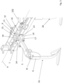
- FIG.2 shows schematically a perspective view of an adjusting means 3 for adjusting the lateral distance of at least one chopping tool 2a of the chopping device 100 relative to the chopping tool 2b or the carrier 1.
- the at least one chopping tool 2a is connected to the adjusting means 3 which is oriented transversely to the longitudinal axis 4 of the carrier 1 and fastened to the carrier 1.
- the adjusting means 3 can be actuated without tools in order to adjust the lateral distance of the at least one chopping tool 2a relative to the carrier 1 and/or the other chopping tool 2b, 2c.
- the chopping tool 2a is detachably arranged on a support arm 5 which projects laterally beyond the carrier 1.
- the support arm 5 and the chopping tool 2a arranged thereon are laterally adjustably connected to the carrier 1 by the adjustment means 3.
- the chopping tool 2a is detachably fastened to the support arm 5 in a vertical guide 6 by means of a screw connection 7.
- a shaft section 8 of the chopping tool 2a is guided relatively movably within the vertical guide 6.
- the chopping tools 2a, 2b, 2c are designed as chopping shares in the embodiment shown.
- the chopping tools 2a, 2b, 2b can also be designed as knives.
- the adjustment means 3 comprises a self-locking drive 9 which in the embodiment shown is designed as a linear drive, in particular as a threaded spindle 10.
- the threaded spindle 10 which is designed with an external thread, has a hand crank 11 at one end, with which the threaded spindle 10 can be rotated clockwise and counterclockwise.
- the threaded spindle 10 extends through a component 12 having an internal thread section, which is arranged on the carrier 1, as can be seen from Fig.3 is evident.
- the adjustment means 3 further comprises a position-adjustable linear guide 13.
- the linear guide 13 has at least one cylindrical guide rod 14, the position of which relative to the carrier 1 can be changed by the drive 9 connected to the at least one guide rod 14.
- two guide rods 14 are provided, which are arranged axially parallel to the threaded spindle 10.
- the guide rods 14 have a length that exceeds the width of the carrier 1.
- the ends of the guide rods 14 protrude beyond the carrier 1 in sections on both sides of the carrier 1.
- the guide rods 14 are each mounted in a bushing 15 so that they can be moved axially.
- the bushings 15 are attached to the carrier 1.
- the linear guide 13 serves not only to guide the chopping tool 2a when moving laterally Adjustment also serves to prevent twisting around the longitudinal axis of the threaded spindle 10.
- Plate-shaped connecting elements 16, 17 are detachably arranged at the free ends of the guide rods 14.
- One end of the threaded spindle 10 is rotatably mounted in the connecting element 16.
- the hand crank 11 is attached to the mounted end of the threaded spindle 10.
- the hand crank 11 has a crank body 18 and a handle 19 pivotably connected to the crank body 18.
- Fig.2 shows the hand crank 11 in a locked position.
- the handle 19 is moved into a position parallel to the threaded spindle 10, in which the handle 19 is in positive engagement with a recess 20 on the connecting element 16.
- the linear guide 13 is assigned at least one scale (not shown) which serves to visualize the set position.
- the scale is arranged on one of the guide rods 14, whereby the set lateral distance of the chopping tool 2a can be read.
- FIG.3 shows schematically a perspective partial view of the chopping device 100 according to Fig.2 in a view rotated by 180° around a vertical axis.
- the connecting element 17 is connected to the ends of the guide rods 14.
- the support arm 5 with the chopping tool 2a arranged on it is arranged on the side of the connecting element 17 facing away from the carrier 1.
- Fig.4 is a schematic perspective view of an adjusting means 3 for adjusting a lateral distance of the chopping tool 2a of the chopping device 100 according to a further embodiment.
- the illustration in Fig.5 shows schematically a perspective partial view of the chopping device 100 according to Fig.4 in a view rotated by 180° around a vertical axis.
- the previously used reference numerals have been retained.
- the embodiment according to the Fig.4 and 5 differs from the previous one based on the Fig. 2 and 3 described embodiment by the adjustment means 3 used.
- the adjustment means 3 comprises a drive motor 21 as a linear drive, which drives the threaded spindle 10.
- the drive motor 21 itself can also be provided with a threaded spindle.
- the threaded spindle 10 is rotated clockwise or anti-clockwise and the rotary movement of the threaded spindle 10 is transmitted to the linear guide 13 in order to bring about the tool-free lateral adjustability of the chopping tool 2a relative to the carrier 1 and/or the chopping tool 2b.
- the latter is connected to a computing unit 24, for example by a bus system 22 or a cable connection with a control unit 23 assigned to the hoeing device 100.
- the control unit 23 can be arranged on a tractor (not shown) on which the hoeing device 100 is arranged.
- the control unit 23 can comprise a display unit 25 which shows the currently set position of the at least one laterally adjustable hoeing tool 2a.
- the control unit 23 can have an input means 26 which enables an operator to enter a lateral distance to be set for the at least one laterally adjustable hoeing tool 2a. Based on the input, the control unit 23 can generate corresponding control signals and transmit them via the bus system 22 or a cable connection which serve to control the drive motor 21. Wireless communication for transmitting control signals to the respective drive motor 21 is also conceivable.
- the electrical adjustment of the lateral distance of the at least one laterally adjustable hoeing tool 2a from a tractor cab allows easy adjustment even while driving.
- the contactless row detection device 27 arranged on the frame 101 is connected to the control unit 23 via the bus system 22, a cable connection or wirelessly.
- the row detection device 27 is designed as a camera.
- the row detection device 27 can be used to continuously determine the row spacing 105 between two rows of cultivated plants 104 or the position of the cultivated plants 104 viewed laterally to the direction of travel FR in order to adjust the lateral distance of one or both hoeing tools 2a, 2c to one another or to the carrier 1 if necessary.
- the lateral distance of the hoeing tools 2a, 2c can preferably be adjusted independently of one another.
- the setting of the lateral distance of the hoeing tool(s) 2a, 2c can be optimized depending on the cultivated plant 104 in the row and the driving speed of the work machine.
- the row detection device 27 and/or the detection means 28 can also be connected to a separate computing unit. By means of the row detection device 27 and/or the detection means 28, characteristic properties of the crops 104 grown in rows can be determined, wherein the computing unit 24 is set up to compare the characteristic properties with comparison values stored in the computing unit 24, and wherein the computing unit 24 is set up to adjust the lateral distance of the hoeing tool(s) 2a, 2c on the basis of these values by means of the drive motor 21, in particular continuously.
- the row detection device 27 on the respective hoeing device 100 and the row detection device 111 on the support beam 101 also enable the work result to be checked by means of a before-and-after comparison.
- either the row detection device 111 on the support beam 101 or the row detection device 27 on the respective hoeing device 100 functions as a predictive row detection device for a before-and-after comparison.
- the signals from the row detection device 27 and/or the row detection device 111 can be used to control the drive motor 21 on the hoeing device 100.
- the control unit 23 is also connected to the row detection device 111 through the Bus system 22 in order to receive and evaluate signals from the row detection device 111.
- the computing unit 24 of the control unit 23 is set up to carry out the before-after comparison.
- a data comparison can be used to determine whether the crops detected by the row detection device 111 are also detected by the row detection device 27 after the work process. If this is not the case, the hoeing tools 2a, 2c can be corrected accordingly. It is also possible to visualize the image data of the row detection devices 111 and/or 27 on the display unit 25, preferably together with the distances shown between the hoeing tools 2a, 2c, for example in an "augmented reality display".
- the hoeing result between the crop rows can be displayed, evaluated or assessed by the before and after comparison.
Landscapes
- Life Sciences & Earth Sciences (AREA)
- Engineering & Computer Science (AREA)
- Mechanical Engineering (AREA)
- Soil Sciences (AREA)
- Environmental Sciences (AREA)
- Zoology (AREA)
- Guiding Agricultural Machines (AREA)
- Soil Working Implements (AREA)
- Harvester Elements (AREA)
- Harvesting Machines For Specific Crops (AREA)
Applications Claiming Priority (2)
| Application Number | Priority Date | Filing Date | Title |
|---|---|---|---|
| DE102019121322.3A DE102019121322A1 (de) | 2019-08-07 | 2019-08-07 | Hackvorrichtung |
| EP20190007.3A EP3772265B1 (fr) | 2019-08-07 | 2020-08-07 | Dispositif de houe |
Related Parent Applications (2)
| Application Number | Title | Priority Date | Filing Date |
|---|---|---|---|
| EP20190007.3A Division-Into EP3772265B1 (fr) | 2019-08-07 | 2020-08-07 | Dispositif de houe |
| EP20190007.3A Division EP3772265B1 (fr) | 2019-08-07 | 2020-08-07 | Dispositif de houe |
Publications (2)
| Publication Number | Publication Date |
|---|---|
| EP4356704A2 true EP4356704A2 (fr) | 2024-04-24 |
| EP4356704A3 EP4356704A3 (fr) | 2024-07-24 |
Family
ID=71995829
Family Applications (2)
| Application Number | Title | Priority Date | Filing Date |
|---|---|---|---|
| EP20190007.3A Active EP3772265B1 (fr) | 2019-08-07 | 2020-08-07 | Dispositif de houe |
| EP24156509.2A Pending EP4356704A3 (fr) | 2019-08-07 | 2020-08-07 | Dispositif de houe |
Family Applications Before (1)
| Application Number | Title | Priority Date | Filing Date |
|---|---|---|---|
| EP20190007.3A Active EP3772265B1 (fr) | 2019-08-07 | 2020-08-07 | Dispositif de houe |
Country Status (2)
| Country | Link |
|---|---|
| EP (2) | EP3772265B1 (fr) |
| DE (1) | DE102019121322A1 (fr) |
Cited By (1)
| Publication number | Priority date | Publication date | Assignee | Title |
|---|---|---|---|---|
| CH722036A1 (de) * | 2024-08-13 | 2026-02-27 | Strebel Maschinen Ag | Hackvorrichtung zur Entfernung von Unkraut |
Families Citing this family (5)
| Publication number | Priority date | Publication date | Assignee | Title |
|---|---|---|---|---|
| FR3129268B1 (fr) * | 2021-11-25 | 2023-11-24 | Naio Tech | Bloc outil pour machine agricole, machine agricole équipée d’un tel bloc outil et procédé de réglage du bloc outil |
| DE102021131695A1 (de) | 2021-12-01 | 2023-06-01 | Lemken Gmbh & Co. Kg | Werkzeugträgereinheit für eine gezogene reihenabhängige Bodenbearbeitungsvorrichtung |
| DE102022104913A1 (de) * | 2022-03-02 | 2023-09-07 | Lemken Gmbh & Co. Kg | Landwirtschaftliches Bodenbearbeitungsgerät |
| DE102022105483A1 (de) * | 2022-03-09 | 2023-09-14 | Claas E-Systems Gmbh | Arbeitsmaschine mit einer Hackvorrichtung |
| CA3218024A1 (en) * | 2023-02-08 | 2025-04-15 | Treffler Maschinenbau Gmbh & Co. Kg | Width-variable tillage device |
Citations (3)
| Publication number | Priority date | Publication date | Assignee | Title |
|---|---|---|---|---|
| GB633740A (en) | 1947-06-20 | 1949-12-19 | Albert Edward Brookes | Improvements in or relating to cultivating machines |
| EP0426960A2 (fr) | 1989-11-04 | 1991-05-15 | Rabewerk GmbH + Co. | Bineuse pour machine agricole |
| AT520294B1 (de) | 2018-02-01 | 2019-03-15 | Agrom Kg | Hackvorrichtung |
Family Cites Families (7)
| Publication number | Priority date | Publication date | Assignee | Title |
|---|---|---|---|---|
| US479754A (en) * | 1892-07-26 | Adjusting device for cultivators | ||
| US982912A (en) * | 1910-03-02 | 1911-01-31 | John R West | Cultivator. |
| GB191314449A (en) * | 1913-06-23 | 1914-04-30 | Charles Weir | Improvements in Hoes or Scarifiers. |
| FR1006494A (fr) * | 1948-01-22 | 1952-04-23 | Bungartz & Co | Dispositif pour la fixation et le réglage d'outils multiples pour le travail de la terre |
| DE1195536B (de) * | 1962-04-12 | 1965-06-24 | Adalbert Joachim Von Flottwell | Vorrichtung zur Erzeugung von quer zur Fahrtrichtung hin und her gehenden Werkzeug-bewegungen fuer die Bearbeitung von Einzel-pflanzenkulturen |
| US4033417A (en) * | 1974-04-10 | 1977-07-05 | Maschinenfabrik Rau Ohg | Agricultural machine |
| DE4135414A1 (de) * | 1991-10-26 | 1993-04-29 | Bareiss Manfred Dipl Ing Fh | Maschine zum hacken, zur pflanzenpflege und zur unkrautbekaempfung |
-
2019
- 2019-08-07 DE DE102019121322.3A patent/DE102019121322A1/de active Pending
-
2020
- 2020-08-07 EP EP20190007.3A patent/EP3772265B1/fr active Active
- 2020-08-07 EP EP24156509.2A patent/EP4356704A3/fr active Pending
Patent Citations (3)
| Publication number | Priority date | Publication date | Assignee | Title |
|---|---|---|---|---|
| GB633740A (en) | 1947-06-20 | 1949-12-19 | Albert Edward Brookes | Improvements in or relating to cultivating machines |
| EP0426960A2 (fr) | 1989-11-04 | 1991-05-15 | Rabewerk GmbH + Co. | Bineuse pour machine agricole |
| AT520294B1 (de) | 2018-02-01 | 2019-03-15 | Agrom Kg | Hackvorrichtung |
Cited By (1)
| Publication number | Priority date | Publication date | Assignee | Title |
|---|---|---|---|---|
| CH722036A1 (de) * | 2024-08-13 | 2026-02-27 | Strebel Maschinen Ag | Hackvorrichtung zur Entfernung von Unkraut |
Also Published As
| Publication number | Publication date |
|---|---|
| EP3772265C0 (fr) | 2024-10-09 |
| EP3772265B1 (fr) | 2024-10-09 |
| EP4356704A3 (fr) | 2024-07-24 |
| DE102019121322A1 (de) | 2021-02-11 |
| EP3772265A1 (fr) | 2021-02-10 |
Similar Documents
| Publication | Publication Date | Title |
|---|---|---|
| EP3772265B1 (fr) | Dispositif de houe | |
| EP2283719B1 (fr) | Agencement pour l'installation réglable latéralement d'un appareil agricole sur un véhicule | |
| DE602004004307T2 (de) | Vorrichtung zur Höheneinstellung eines Spindelmähers | |
| EP3689118A1 (fr) | Outil de travail agricole, timon et combinaison de véhicule de traction et d'outil de travail | |
| DE102009047181B4 (de) | Landwirtschaftliches Bodenbearbeitungsgerät zur Befestigung an einem Fahrzeug | |
| DE102016212201A1 (de) | Anordnung zur selbsttätigen Führung eines Gerätes | |
| DE102018213212A1 (de) | Höhenverstellbare Kurvenbahn | |
| DE19845666B4 (de) | Lenkautomatik mit Ultraschall-Ortungsvorrichtung | |
| EP3357323B1 (fr) | Rainure de came réglable en hauteur | |
| EP3417685B1 (fr) | Procédé de détermination d'une grandeur physique d'un bras supérieur | |
| EP3165090A1 (fr) | Système de commande et/ou de réglage d'une machine agricole | |
| EP3721691A1 (fr) | Procédé de commande du fonctionnement d'un accessoire | |
| EP4101275B1 (fr) | Appareil accessoire destiné au traitement du sol | |
| EP3449710A1 (fr) | Dispositif de travail agricole | |
| EP3689119A1 (fr) | Outil de travail agricole, dispositif timon et combinaison de véhicule de traction et d'outil de travail | |
| EP3243372B1 (fr) | Procédé de réglage d'un angle de coupe d'un outil avant disposé sur une moissonneuse automobile | |
| EP3545748B2 (fr) | Appareil adaptable de récolte | |
| EP4275463B1 (fr) | Outil de travail agricole | |
| EP3735810B1 (fr) | Dispositif d'accouplement pour un attelage | |
| EP4272527A1 (fr) | Outil de montage pour l'usinage de champs | |
| EP3498065B1 (fr) | Procédé de commande de mouvement d'un relevage à trois points d'un tracteur | |
| EP4346372B1 (fr) | Systeme d'entrainement et d'alignement d'un outil agricole au moyen d'un circuit hydraulique | |
| EP3791706B1 (fr) | Machine de travail agricole pourvue d'outil de travail réglable en hauteur | |
| EP4074157B1 (fr) | Machine agricole pourvue d'au moins un bras | |
| EP4663003A1 (fr) | Véhicule utilitaire destiné à comprimer une récolte |
Legal Events
| Date | Code | Title | Description |
|---|---|---|---|
| PUAI | Public reference made under article 153(3) epc to a published international application that has entered the european phase |
Free format text: ORIGINAL CODE: 0009012 |
|
| STAA | Information on the status of an ep patent application or granted ep patent |
Free format text: STATUS: THE APPLICATION HAS BEEN PUBLISHED |
|
| AC | Divisional application: reference to earlier application |
Ref document number: 3772265 Country of ref document: EP Kind code of ref document: P |
|
| AK | Designated contracting states |
Kind code of ref document: A2 Designated state(s): AL AT BE BG CH CY CZ DE DK EE ES FI FR GB GR HR HU IE IS IT LI LT LU LV MC MK MT NL NO PL PT RO RS SE SI SK SM TR |
|
| REG | Reference to a national code |
Ref country code: DE Ref legal event code: R079 Free format text: PREVIOUS MAIN CLASS: A01B0069000000 Ipc: A01B0013040000 |
|
| PUAL | Search report despatched |
Free format text: ORIGINAL CODE: 0009013 |
|
| AK | Designated contracting states |
Kind code of ref document: A3 Designated state(s): AL AT BE BG CH CY CZ DE DK EE ES FI FR GB GR HR HU IE IS IT LI LT LU LV MC MK MT NL NO PL PT RO RS SE SI SK SM TR |
|
| RIC1 | Information provided on ipc code assigned before grant |
Ipc: A01B 69/00 20060101ALI20240619BHEP Ipc: A01B 63/24 20060101ALI20240619BHEP Ipc: A01B 63/02 20060101ALI20240619BHEP Ipc: A01B 13/04 20060101AFI20240619BHEP |
|
| STAA | Information on the status of an ep patent application or granted ep patent |
Free format text: STATUS: REQUEST FOR EXAMINATION WAS MADE |
|
| STAA | Information on the status of an ep patent application or granted ep patent |
Free format text: STATUS: EXAMINATION IS IN PROGRESS |
|
| 17P | Request for examination filed |
Effective date: 20250124 |
|
| 17Q | First examination report despatched |
Effective date: 20250228 |