EP4357226A1 - Fahrradparksystem - Google Patents
Fahrradparksystem Download PDFInfo
- Publication number
- EP4357226A1 EP4357226A1 EP23204052.7A EP23204052A EP4357226A1 EP 4357226 A1 EP4357226 A1 EP 4357226A1 EP 23204052 A EP23204052 A EP 23204052A EP 4357226 A1 EP4357226 A1 EP 4357226A1
- Authority
- EP
- European Patent Office
- Prior art keywords
- wheel
- bicycle parking
- clamp
- catcher
- bicycle
- Prior art date
- Legal status (The legal status is an assumption and is not a legal conclusion. Google has not performed a legal analysis and makes no representation as to the accuracy of the status listed.)
- Pending
Links
Images



Classifications
-
- B—PERFORMING OPERATIONS; TRANSPORTING
- B62—LAND VEHICLES FOR TRAVELLING OTHERWISE THAN ON RAILS
- B62H—CYCLE STANDS; SUPPORTS OR HOLDERS FOR PARKING OR STORING CYCLES; APPLIANCES PREVENTING OR INDICATING UNAUTHORIZED USE OR THEFT OF CYCLES; LOCKS INTEGRAL WITH CYCLES; DEVICES FOR LEARNING TO RIDE CYCLES
- B62H3/00—Separate supports or holders for parking or storing cycles
- B62H3/04—Separate supports or holders for parking or storing cycles involving forked supports of brackets for holding a wheel
-
- B—PERFORMING OPERATIONS; TRANSPORTING
- B62—LAND VEHICLES FOR TRAVELLING OTHERWISE THAN ON RAILS
- B62H—CYCLE STANDS; SUPPORTS OR HOLDERS FOR PARKING OR STORING CYCLES; APPLIANCES PREVENTING OR INDICATING UNAUTHORIZED USE OR THEFT OF CYCLES; LOCKS INTEGRAL WITH CYCLES; DEVICES FOR LEARNING TO RIDE CYCLES
- B62H3/00—Separate supports or holders for parking or storing cycles
- B62H3/08—Separate supports or holders for parking or storing cycles involving recesses or channelled rails for embracing the bottom part of a wheel
-
- E—FIXED CONSTRUCTIONS
- E04—BUILDING
- E04H—BUILDINGS OR LIKE STRUCTURES FOR PARTICULAR PURPOSES; SWIMMING OR SPLASH BATHS OR POOLS; MASTS; FENCING; TENTS OR CANOPIES, IN GENERAL
- E04H6/00—Buildings for parking cars, rolling-stock, aircraft, vessels or like vehicles, e.g. garages
- E04H6/005—Garages for vehicles on two wheels
Definitions
- the invention relates to a bicycle parking system for enabling a user to park its bicycle, comprising a bicycle parking support that defines a bicycle parking spot.
- Such a bicycle parking system is well-known, wherein the known bicycle parking system is also known as a bicycle rack.
- the bicycle rack comprises a number of front wheel supporting brackets that are arranged next to each other such that a number of bicycles may be parked next and parallel to each other.
- the front wheel supporting brackets are alternately arranged at a high or low position.
- a disadvantage of the known bicycle parking system is that the front wheel supports are configured for receiving bicycle tires with a predetermined width and with a predetermined diameter. As a result, a number of bicycles cannot be parked within the known bicycle parking system and are parked somewhere on the street.
- the known bicycle parking system also results in incorrect or double parking of bicycles, or inefficient use, which may lead to damage to bicycles parked within the known bicycle parking system.
- the invention provides a bicycle parking system for enabling a user to park its bicycle, comprising a bicycle parking support that defines a bicycle parking spot, wherein the bicycle parking support comprises:
- the person When a person wants to park a bicycle in the bicycle parking system, the person inserts a wheel of the bicycle, which may be the front wheel or the rear wheel of the bicycle, into the wheel catcher. While inserting the wheel into the wheel catcher, the wheel is received within the bottom wheel clamp from above due to which the wheel catcher may be rotated from the receiving position into the parking position. Alternatively, the inserted wheel may contact the front wheel clamp firstly due to which the wheel catcher also may be rotated from the receiving position into the parking position. As a result of the rotational movement of the wheel catcher, the front wheel clamp and the bottom wheel clamp are forced against the front wheel, thereby clamping the wheel between the front wheel clamp, the bottom wheel clamp and the back wheel clamp.
- a wheel of the bicycle which may be the front wheel or the rear wheel of the bicycle
- the wheel with the smaller diameter When a wheel with a smaller diameter is parked in the bicycle parking support, the wheel with the smaller diameter also enters the wheel catcher and is also received by the bottom wheel clamp from above, or contacts the front wheel clamp firstly. Therefore, the front wheel clamp and the bottom wheel clamp both are again rotated around the rotational axis until forced against and clamping the wheel with the smaller diameter.
- the smaller the diameter of the wheel the larger the rotational movement of the wheel catcher and thereby the front wheel clamp and the bottom wheel clamp thereof, and vice versa.
- the bicycle parking system is enabled to stall bicycles with different wheel diameters.
- An advantage of the invention is, thus, that a broad range of different wheel diameters may be parked within the bicycle parking system, wherein both a front and rear wheel of a bicycle may be inserted into the wheel catcher.
- a further advantage of the bicycle parking system according to the invention is that it may be used in a high-low configuration. This may be made possible by clamping the wheel from the front and from below. This is advantageous, as it may increase the capacity of the bicycle parking system.
- the wheel of the bicycle parked within the bicycle parking system according to the invention is clamped at three different points, which may provide a reliable clamping of the wheel. This is advantageous, as it may prevent the bicycle from falling out of the bicycle parking system unintentionally.
- the bicycle parking support comprises a drive gutter configured for receiving at least a wheel of a bicycle and having a first supporting end and a second supporting end, opposite to the first supporting end in the longitudinal direction of the drive gutter,
- the front wheel clamp and the bottom wheel clamp are fixed with respect to each other. In the context of the present application, this has to be understood as that the distance between the front wheel clamp and the bottom wheel clamp is always the same.
- the front wheel clamp, the bottom wheel clamp and the rotational axis together define a triangle, when seen from the side. According to this embodiment, rotational movement of the bottom wheel clamp may result in substantially the same rotational movement of the front wheel clamp. This is advantageous, as rotation of the wheel catcher may be achieved in a relatively easy manner.
- the clamping force applied to the inserted wheel may be enlarged in an advantageous manner, in comparison to the prior art, due to the increased arm defined by the distance between the front wheel clamp and the rotation axis.
- the bicycle parking support comprises a drive gutter configured for receiving at least a wheel of a bicycle and having a first supporting end and a second supporting end, opposite to the first supporting end in the longitudinal direction of the drive gutter,
- the front wheel clamp, the bottom wheel clamp and/or the back wheel clamp are substantially V-shaped.
- the V-shaped front wheel clamp, the V-shaped bottom wheel clamp and the V-shaped back wheel clamp are formed by means of a V-shaped opening, for example, in a plate-shaped element.
- the V-shape has as a property that the further the wheel is inserted in into the front wheel clamp, the bottom wheel clamp and/or the back wheel clamp, the further the distance between the side edges defining the V-shape becomes. This may be understood as the smaller the width of the tire on the wheel, the further the tire is enabled to move into the front wheel clamp, the bottom wheel clamp and/or the back wheel clamp.
- An advantage of the V-shaped front wheel clamp, bottom wheel clamp and/or back wheel clamp is the ability to clamp a broad range of different tire widths.
- the wheel catcher comprises a wheel receiving opening configured for receiving at least a part of the wheel and extending between the front wheel clamp and the bottom wheel clamp.
- the drive gutter at the second supporting end thereof, projects into the wheel catcher via the wheel receiving opening.
- the wheel of a bicycle to be parked may enter the wheel catcher at least partially. Therefore, the wheel is received within the wheel catcher partially, while being clamped by among others the front wheel clamp and the bottom wheel clamp.
- the wheel receiving opening for example, may prevent the front wheel of a parked bicycle from rotating around its steering axis while being parked. This embodiment, therefore, may provide a secure parking of a bicycle.
- the bicycle parking system comprises a mount arranged at the wheel catcher and configured the bicycle parking support to another component of the bicycle parking system.
- the mount is arranged at or near the second supporting end of the drive gutter and configured for mounting the bicycle parking support to another component of the bicycle parking system.
- the wheel catcher is arranged at the mount in such manner that the wheel catcher is rotatable about the rotational axis.
- the bicycle parking system comprises a resilient part, such as a spring, arranged at or near the wheel catcher, wherein the resilient part is configured for moving the wheel catcher into the receiving position when the wheel is removed from the wheel catcher.
- a resilient part such as a spring
- the resilient part is configured for moving the wheel catcher into the receiving position when the wheel is removed from the wheel catcher.
- the resilient part is provided between the wheel catcher and the mount.
- the resilient part may be used for connecting the wheel catcher to the mount, and for moving the wheel catcher into the receiving position when a parked bicycle is removed. This is advantageous, as the resilient part may keep the bicycle parking system constructively relatively simple.
- the bicycle parking system comprises a movement limiter configured for limiting the rotational movement of the wheel catcher between the receiving position and the parking position.
- the movement limiter is provided at the wheel catcher and the mount. The movement limiter advantageously prevents the wheel catcher from moving into a position in which no bicycle may be parked at the bicycle parking support, or in which a parked bicycle may not be removed from the bicycle parking support.
- the bicycle parking system comprises a housing having a parking space defined therein in which the bicycle park support is arranged, wherein the housing has a door portion for providing access to the parking space.
- the housing has a lock for locking or opening the door portion to control access to the parking space within the housing.
- a bicycle owner may be enabled to park a bicycle in a parking space such that the bicycle may be parked indoor and/or in a dry environment.
- the housing thus, may protect the bicycle against environmental influences.
- due to the lock for locking or opening the door portion access to the parking space may be restricted to persons who actually park a bicycle therein. It, therefore, is more difficult for thieves to access and steal a bicycle parked in the bicycle parking system.
- An advantage of this embodiment is that a bicycle may be parked in a safe way while being protected against environmental influences.
- a supporting beam is horizontally arranged within the housing, wherein the bicycle parking support, in particular the drive gutter at the second supporting end thereof is arranged at the supporting beam.
- the bicycle parking support is releasable arranged at the supporting beam such that the position of the bicycle parking support within the housing is adjustable.
- the bicycle parking system may comprise two or more bicycle parking supports, such that multiple bicycles may be parked therein. As the width of bicycles, in particular the width of the handle bars thereof, varies, the distance between adjacent bicycle parking supports may be too small or too large. According to this embodiment, the bicycle parking support may be released from the supporting beam, to which it is arranged during use, in order to adjust the distance between adjacent bicycle parking supports.
- An advantage of this embodiment is that the distribution of two or more bicycle parking supports may be easily adjusted.
- the bicycle parking system comprises two or more bicycle parking supports arranged next to each other and wherein a top supporting beam and a lower supporting beam are horizontally arranged within the housing, wherein one of the two or more bicycle parking supports is arranged at the top supporting beam, and the other one of the two or more bicycle parking supports is arranged at the lower supporting beam.
- the two or more bicycle parking supports are alternately arranged in a high position and a low position.
- the bicycle parking support comprises a drive gutter configured for receiving at least a wheel of a bicycle and having a first supporting end and a second supporting end, opposite to the first supporting end in the longitudinal direction of the drive gutter,
- the bicycle parking support is configured to be stacked onto another bicycle parking support. Because of the bicycle parking support being configured to be stacked onto a similar bicycle parking support, multiple bicycle parking supports may be stacked onto each other during transport such that the bicycle parking supports may be transported in an efficient manner.
- the wheel catcher is configured to be moved from the receiving position into the parking position by a wheel being inserted into the wheel catcher in an insert direction substantially parallel to the longitudinal direction of the drive gutter.
- the back wheel clamp and the rotational axis are fixed with respect to each other.
- FIG. 1 A schematic overview of a bicycle parking system 1 according to an embodiment of the invention is shown in figure 1 .
- the bicycle parking system 1 may be placed in the center of a city in order to allow residents to park their bicycles in a safe manner.
- the bicycle parking system 1 may be dimensioned such that it may be placed onto a car parking spot. By placing the bicycle parking system 1 onto a parking spot, it does not form any obstruction in the street where it is located.
- the bicycle parking system 1 comprising a housing 2 that defines a bicycle parking space 3 into which one or more bicycles may be parked, and that is placed onto a supporting plate 4.
- the housing 2 may be placed onto a ground frame that may be inserted into the ground, or the housing 2 may be directly connected to the paving stones of the tarmac.
- the housing 2 is provided with a first side wall 5 and a second side wall 6, opposite to the first side wall 5 in the longitudinal direction L of the housing 2.
- Each of the first and second side walls 5, 6 has a semi-egg shape, such that one end of the respective side wall 5, 6 is higher that the opposite end thereof.
- the bicycle parking space 3 between the first and second side walls 5, 6 is roofed by a roofing wall 7.
- the roofing wall 7 comprises a stationary roofing portion 8 and a door portion 9 that is moveable arranged at the stationary roofing portion 8 between an open position, as shown in figure 1 , and a closed position, in which the bicycle parking space 3 is closed off.
- the door portion 9 is connected to the stationary roofing portion 8 such that the door portion 9 may be moved, in particular hinged, in an upwards direction with respect to the stationary roofing portion 8, thereby moving the door portion 9 into the open position.
- a hinging mechanism 10 is provided between the station roofing portion 8 and the door portion 9.
- the hinging mechanism 10 is provided with a Y-shaped arm 11, of which one leg is pivotable connected to the stationary roofing portion 8, one leg is connected to the door portion 9, and one leg is connected to a gas spring 12 that extends between the Y-shaped arm 11 and the stationary roofing portion 8.
- the door portion 9 may be provided with a lock for locking the door portion 9 in the closed position, such that all bicycles parked within the bicycle parking system 1, for example, are not accessible by thieves.
- the lock may be a conventional lock that might be opened by means of a key, but also may be a lock that, for example, might be opened by means of a software application installed on a smartphone of a user, for example, via a Bluetooth ® connection.
- the stationary roofing portion 8 is provided with a top supporting beam 15 and a lower supporting beam 16 that are arranged parallel to each other and to the longitudinal direction L of the bicycle parking system 1.
- Each of the top supporting beam 15 and the lower supporting beam 16 extends over substantially the whole width of the bicycle parking system 1.
- each of the top supporting beam 15 and the lower supporting beam 16, in particular at the upper face thereof, is provided with a plurality of installation slots evenly distributed in the longitudinal direction of the respective supporting beam 15.
- the bicycle parking system 1 is provided with a number of bicycle parking supports 20 that are arranged parallel to each other, and where each bicycle parking support defines a bicycle parking spot. As shown in figure 1 , the bicycle parking supports 20 are arranged in a high-low configuration, which has to be understood as that the bicycle parking supports 20 are alternating between a low orientation, such as the bicycle parking support 20 leftmost in figure 1 , and high orientation, such as the bicycle parking support 20 second from left in figure 1 .
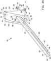
- a bicycle parking support 20 is shown in more detail in figures 2A and 2B .
- the bicycle parking support 20 comprises a drive-up gutter 21 configured for inserting at least a wheel of a bicycle to be parked at the bicycle parking support 20.
- the drive-up gutter 21 comprises a first supporting end 22 configured for abutting on the supporting plate 4, and a second supporting end 23, opposite to the first supporting end 22 in the longitudinal direction of the drive-up gutter 21.
- the drive-up gutter 21 is substantially U-shaped and has a bottom wall 24 and two upstanding side walls 25. Each of the upstanding side walls 25, at the end facing away from the bottom wall 24, is provided with a deflecting edge 26 that extends outwardly from the respective side wall 25.
- the drive-up gutter 21 includes a wheel parking opening 27 extending from the second supporting end 23 towards the first supporting end 22 over a predetermined distance.
- the wheel parking opening 27 is configured for receiving at least a part of a wheel of a bicycle to be parked, and is dimensioned such that bicycles ranging from 20 inch to 28 inch may be received therein.
- a wheel may be inserted into the drive-up gutter 21 by driving the wheel up and into the drive-up gutter 21 until the wheel is received in the wheel parking opening 27.
- the end edge of the bottom wall 24 facing towards the wheel parking opening 27 may be substantially V-shaped, when seen from above, in order to clamp a wheel at the end edge, thereby forming a back wheel clamp.
- an extension adapter 28 is provided at the outer surface of the drive-up gutter 21, which extension adapter 28 is also substantially U-shaped such that is substantially corresponds to the drive-up gutter 21.
- the extension adapted 28 is mounted to the drive-up gutter, in this example, by means of a nut-bolt joint 29.
- the extension adapter 28 may be used for reducing the dimensions of the wheel parking opening 27, in particular the dimension extending in the longitudinal direction of the drive-up gutter 21, such that bicycle wheels with a diameter smaller than 22 inch may be received within the wheel parking opening 27.
- the drive-up gutter 21 is connected to a mount 30 for mounting the bicycle parking support 20 to the top supporting beam 15 or the lower supporting beam 16.
- the mount 30 includes a mounting plate 31 that is connected to the drive-up gutter 21 at the upper side thereof, which mounting plate 31 extends from the second support end 23 downwards and towards the first support end 22 such that the mounting plate 31 is inclined with respect to the drive-up gutter 21.
- the mounting plate 31 is provided with an abutting edge 32 that is configured for abutting against the upper face of one of the top supporting beam 15 and the lower supporting beam 16.
- the abutting edge 32 at the opposite side edges thereof, includes mounting projections 33 to which L-shaped mounting pieces 34 may be connected in order to mount the drive-up gutter 21 to one of the top supporting beam 15 and the lower supporting beam 16, wherein the L-shaped mounting pieces 34 are configured to be inserted partially into the installation slots of the respective supporting beam 15, 16.
- the mounting plate 31 is provided with further mounting projections 35 at the side edges and near the bottom edge thereof, which further mounting projections 35 extend in a direction away from the drive-up gutter 21.
- clamping pieces 36 are provided which are connected to the further mounting projections 35 by a nut-bolt connection 37.
- a rotational bus may be provided between the further mounting projection 35 and the corresponding clamping piece 36 at each side of the mounting plate 31 and around a part of the bolt extending therebetween, wherein the rotational busses provide a fixed rotational connection point.
- Each of the clamping pieces 36 has a hooking part 38 that extends to the other one of the clamping pieces 36 and that is received within a not shown receiving opening defined within the merger between the mounting plate 31 and the further mounting projections 35.
- the nut-bolt connections 38, together with the rotational busses, on both sides of the mounting plate 31 together define a rotational axis A that is substantially transverse to the longitudinal direction of the drive-up gutter 21. As shown in figures 2A and 2B , the rotational axis A is located at a position below the drive-up gutter 21.
- the bicycle parking support 20 further comprises a wheel catcher 50, arranged in front of the mount 30, that is configured for catching and holding a wheel, which may be a front wheel or a rear wheel, of a bicycle to be parked.
- the wheel catcher 50 is arranged at the mounting plate 31 in a rotatable manner, such that the wheel catcher 50 is rotatable about the rotational axis A.
- the wheel catcher 50 is provided with a front wheel clamp 51, in particular a V-shaped wheel clamp, which is arranged at a position above the drive-up gutter 21, and a bottom wheel clamp 52, in particular a V-shaped wheel clamp, which is arranged at a position below the drive-up gutter 21.
- the front and bottom wheel clamps 51, 52 are configured for clamping the wheel of the bicycle in order to maintain the bicycle in the parked position.
- the wheel catcher 50 comprises a main catcher portion 53, which is orientated substantially parallel to the mounting plate 31 when in the position shown in figure 2A , and an upper catcher portion 54 arranged at the upper edge of the main catcher portion 53 and extending in a direction away from the first support end 22 of the drive-up gutter 21, which upper catcher portion 54, at the edge facing away from the main catcher portion 53, has an upper abutting edge 55 extending downwards and substantially transverse to the upper catcher portion 54.
- the wheel catcher 50 comprises a lower catcher portion 56 arranged at the lower edge of the main catcher portion 54 and extending oblique downwards away from the first support end 22 of the drive-up gutter 21, which lower catcher portion 56, at the edge facing away from the main catcher portion 53, has a lower abutting edge 57 extending substantially transverse to the lower catcher portion 56.
- the front wheel clamp 51 is provided within the upper catcher portion 54, and the bottom wheel clamp 52 is provided within the lower catcher portion 56.
- the main catcher portion 53 has a wheel receiving opening 58 defined therein, in which the drive-up gutter 21 partially extends such that a wheel may be inserted into the wheel receiving opening 58 in an insert direction E.
- the wheel receiving opening 58 merges into a first clamp opening 59 defined by the front wheel clamp 51.
- the wheel receiving opening 58 merges into a second clamp opening 60 defined by the bottom wheel clamp 52.
- the front wheel clamp 51 and the bottom wheel clamp 52 are defined by the edges of the first clamp opening 59 and the second clamp opening 60, respectively, which edges are shielded by means of shielding parts 61.
- the main catcher portion 53 is provided with a connector portion 65, which is substantially triangular shaped and extends substantially transverse to the main catcher portion 53 and towards the mounting plate 31, such that the main catcher portion 53 is at a distance from the mounting plate 31.
- the triangular shaped connector portion 65 is clamped between one of the further mounting projections 35 and one of the clamping pieces 36, and arranged around the rotational busses provided therebetween.
- the connector portion 65 has a movement limiting groove 67, also referred to as a movement limiter, extending therethrough, through which the hooking part 38 of the respective clamping piece 36 projects.
- the dimensions of the movement limiting groove 67 and the hooking part 38 are chosen such that the wheel catcher 50 is enabled to rotate around the rotational axis A in a rotation direction R when a wheel is inserted into or removed from the wheel catcher 50, wherein the movement limiting groove 67 limits the rotational movement of the wheel catcher 50. As a result, the wheel catcher is prevented from rotating into a position in which a wheel may not be inserted into the wheel catcher 50.
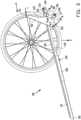
- the rotational axis A, the front wheel clamp 50 and the bottom wheel clamp 51 together define a triangular when seen from the side.
- a user may drive a bicycle up the drive-up gutter 21 until the front or rear wheel reaches the wheel parking opening 27 within the drive-up gutter 21.
- the wheel will fall into the wheel parking opening 27 under influence of gravity.
- the wheel will contact the front wheel clamp 51.
- the wheel catcher 50 may rotate clockwise in rotation direction R until the bottom wheel clamp 52 abuts against the wheel.
- the wheel is clamped between the front wheel clamp 51, the bottom wheel clamp 52 and the end edge of the bottom wall 24 of the drive-up gutter 21. It is emphasized, as clearly shown in figure 3 , that the rotational axis A is located outside the outer circumference of the inserted wheel, when seen from aside. The wheel, thus, is clamped at three points and therefore a reliable bicycle parking spot is defined.
- a resilient part such as a spring, may be arranged in or at the wheel catcher 50 in order to force the wheel catcher 50 to return to the position as shown in figure 2B when a parked bicycle is removed from the bicycle parking support 20.
- the wheel catcher 50 may be forced to return to the position as shown in figure 2B by removing the front wheel from the wheel catcher 50.
- a resilient part is provided or alternatively, during use, a user may drive a bicycle up the drive-up gutter 21 until the front or rear wheel reaches the wheel parking opening 27 within the drive-up gutter 21. When the front side of the wheel is moved far enough beyond the end edge of the bottom wall 24, the wheel will fall into the wheel parking opening 27 under influence of gravity.
- the wheel catcher 50 may rotate counter-clockwise in rotation direction R until the front wheel clamp 51 abuts against the wheel, thereby clamping the wheel is clamped the front wheel clamp 51, the bottom wheel clamp 52 and the end edge of the bottom wall 24 of the drive-up gutter 21, which is the back wheel clamp.
- any width of bicycle wheel may be clamped.
- the smaller the width of the wheel the further the wheel may be moved into the front wheel clamp 51, the bottom wheel clamp 52 and the end edge of the bottom wall 24 of the drive-up gutter 21, and vice versa.
- the wheel catcher 50 may rotate further in the rotational direction R, in particular counter-clockwise, when a smaller wheel, in comparison with the wheel shown in figure 3 , is inserted. This is caused by the wheel moving against the front wheel clamp 51 or alternatively against the bottom wheel clamp 52, thereby forcing the other one of the front wheel clamp 51 and the bottom wheel clamp 52 against the wheel to clamp it. Therefore, the bicycle parking support 20 is suitable for parking bicycles with different wheel diameters.
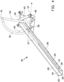
- FIG 4 An alternative embodiment of the bicycle parking support 20 is shown in figure 4 .
- the bicycle parking support 20 also comprises a drive-up gutter 21 similar to the drive-up gutter 20 of figures 1-3 , such that may be refrained from reintroducing likewise or similar aspects.
- the embodiment of figure 4 differs from the embodiment shown in figures 1-3 in that the main catcher portion 53 is formed by two tubes running parallel to each other, which two tubes at the upper end thereof merge into a front wheel clamp 51. At the lower end, the two tubes are connected to a L-shaped plate of which the upstanding part comprises the bottom wheel clamp 52, wherein the L-shaped plate is connected to the connector portions 65.
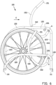
- FIG. 5 An alternative embodiment of the bicycle parking system 100 is shown in figure 5 , of which a side view is shown in figure 6 .
- the bicycle parking system 100 is also provided with a number of bicycle parking supports 120 that are arranged parallel to each other, and wherein each bicycle parking support 120 defines a bicycle parking spot configured for receiving a wheel in an insert direction E.
- the bicycle parking supports 120 are arranged in a high-low configuration, which has to be understood as that the bicycle parking supports 120 are alternating between a low orientation, such as the left bicycle parking support 20 in figure 5 , and a high orientation, such as the right bicycle parking support 120 in figure 5 .
- the bicycle parking supports 120 are arranged at frame beams 110, 111 extending substantially transverse to the insert direction E.
- each of the bicycle parking supports 120 has a first supporting bar 121 and a second supporting bar 122 that are arranged parallel to each other and partially at a distance from each other.
- Each of the first supporting bar 121 and the second supporting bar 122 is substantially shaped as an inverse U, when seen from aside, wherein the first and second supporting bars 121, 122 of the bicycle parking support 120 in the high orientation are arranged at spacers 123 for placing the first and second supporting bars 121, 122 at a height with respect to the underground and the frame beams 110, 111 to which the first and second supporting bars 121, 122 are secured.
- the first and second supporting bars 121, 122 When seen in the insert direction E, the first and second supporting bars 121, 122 are placed initially against each other or very close to each other. Subsequently, the first and second supporting bars 121, 122 are running upwards and away from each other, thereby defining a V-shaped part 124 when seen in the insert direction E.
- the V-shaped part 124 defines a rear wheel clamp 124.
- the first and second supporting bars 121, 122 run substantially parallel to and at a distance from each other, thereby defining a receiving opening 125 in which a wheel may be received.
- an abutment rod 126 is arranged between the first and second supporting bars 121, 122 against which the inserted wheel may abut.
- Each of the parking supports 120 has a wheel catcher 150, at the receiving opening 125, wherein the wheel catcher is configured for catching and holding a wheel.
- the wheel catcher 150 is arranged rotatably at the first and second supporting bars 121, 122, such that the wheel catcher is rotatable around a rotational axis A, which rotational axis A is located behind the abutment rod 126, when seen in the insertion direction E. Furthermore, as shown in figure 6 , the rotational axis A is located outside the outer circumference of the inserted wheel, when seen from aside.
- the wheel catcher 150 comprises a front wheel clamp 151, in particular a V-shaped front wheel clamp, which front wheel clamp 151 is arranged at a position above the first and second supporting bars 121, 122, and a bottom wheel clamp 152, in particular a V-shaped bottom wheel clamp 152, which is arranged at a position below the first and second supporting bars 121, 122.
- the front and bottom wheel clamps 151, 152 are configured for clamping the wheel of the bicycle in order to maintain the bicycle in the parked position.
- Figure 6 clearly shows that the front wheel clamp 151, the bottom wheel clamp 152 and the rotational axis A together define a triangle, when seen from aside.
- the wheel catcher 150 further comprises a main catcher portion 153 that extends between the front wheel clamp 151 and the bottom wheel clamp 152 and into which a wheel may be caught.
- the wheel catcher 150 is manufactured from two catcher rods 154 that merge into the V-shaped front wheel clamp 151 at the upper end thereof, and into the V-shaped bottom wheel clamp 152 at the lower end thereof.
- the catcher rods 154 extend, in particular in a substantially V-shape, from the V-shaped bottom wheel clamp 152 towards the rotational axis A in order to arrange the wheel catcher 150 at the rotational axis A.
- Each wheel catcher 150 is provided with a limiting projection 160, also called movement limiter, preferably with two limiting projections 160, which limiting projections 160 are arranged at the sides of outward facing side of the catcher rods 154.
- the limiting projections 160 may be arranged at the catcher rods 154 at a level above the first and second supporting rods 121, 122, or at a level below the first and second supporting rods 121, 122.
- the limiting projections 160 are configured for limiting rotational movement of the wheel catcher 150 around the rotational axis A.
- the abutment rod 126 optionally, may also be used for limiting rotational movement of the wheel catcher 150 around the rotational axis A.
- the operation of the bicycle parking system 100 corresponds to the operation of the bicycle parking system 1 as shown in figure 1 .
Landscapes
- Engineering & Computer Science (AREA)
- Architecture (AREA)
- Mechanical Engineering (AREA)
- Civil Engineering (AREA)
- Structural Engineering (AREA)
- Handcart (AREA)
Applications Claiming Priority (1)
| Application Number | Priority Date | Filing Date | Title |
|---|---|---|---|
| NL2033332A NL2033332B1 (en) | 2022-10-17 | 2022-10-17 | Bicycle parking system |
Publications (1)
| Publication Number | Publication Date |
|---|---|
| EP4357226A1 true EP4357226A1 (de) | 2024-04-24 |
Family
ID=85158832
Family Applications (1)
| Application Number | Title | Priority Date | Filing Date |
|---|---|---|---|
| EP23204052.7A Pending EP4357226A1 (de) | 2022-10-17 | 2023-10-17 | Fahrradparksystem |
Country Status (2)
| Country | Link |
|---|---|
| EP (1) | EP4357226A1 (de) |
| NL (1) | NL2033332B1 (de) |
Citations (4)
| Publication number | Priority date | Publication date | Assignee | Title |
|---|---|---|---|---|
| JPS5586850U (de) * | 1978-12-11 | 1980-06-16 | ||
| DE20007760U1 (de) * | 1999-08-26 | 2000-07-13 | Schlauch, Roland, 74388 Talheim | Fahrradständer |
| GB2377682A (en) * | 2001-07-20 | 2003-01-22 | Charles Stephen Simmons-Jacobs | Bicycle Rack |
| EP1741623A1 (de) * | 2005-07-04 | 2007-01-10 | Daniel Rudin | Abstellvorrichtung für Zweiräder |
Family Cites Families (2)
| Publication number | Priority date | Publication date | Assignee | Title |
|---|---|---|---|---|
| US10525897B2 (en) * | 2016-11-12 | 2020-01-07 | Jeremy Len Lathrop | Bike rack for truck beds trailers and vehicles |
| EP3984866B1 (de) * | 2020-10-13 | 2025-11-26 | LEITNER S.p.A. | Transporteinheit eines seilbahnsystems mit vorrichtung zum transport von fahrrädern |
-
2022
- 2022-10-17 NL NL2033332A patent/NL2033332B1/en active
-
2023
- 2023-10-17 EP EP23204052.7A patent/EP4357226A1/de active Pending
Patent Citations (4)
| Publication number | Priority date | Publication date | Assignee | Title |
|---|---|---|---|---|
| JPS5586850U (de) * | 1978-12-11 | 1980-06-16 | ||
| DE20007760U1 (de) * | 1999-08-26 | 2000-07-13 | Schlauch, Roland, 74388 Talheim | Fahrradständer |
| GB2377682A (en) * | 2001-07-20 | 2003-01-22 | Charles Stephen Simmons-Jacobs | Bicycle Rack |
| EP1741623A1 (de) * | 2005-07-04 | 2007-01-10 | Daniel Rudin | Abstellvorrichtung für Zweiräder |
Also Published As
| Publication number | Publication date |
|---|---|
| NL2033332B1 (en) | 2024-05-03 |
Similar Documents
| Publication | Publication Date | Title |
|---|---|---|
| US5238125A (en) | Bicycle parking and storage rack | |
| US6123498A (en) | Pivoting vehicle rack | |
| US5947357A (en) | Bicycle rack | |
| US4116341A (en) | Device for storing bicycles in a building | |
| US7021461B1 (en) | Vehicle shipping rack and related methods | |
| CA2089529A1 (en) | Compact disk storage rack | |
| CA2729670A1 (en) | Chock apparatus | |
| NZ563007A (en) | Temporary safety barrier system | |
| US20030034206A1 (en) | Universal ladder lock and method | |
| NL2033332B1 (en) | Bicycle parking system | |
| WO2022159243A1 (en) | Support apparatus for wheeled vehicles | |
| US6739084B1 (en) | Fishing rod rack assembly for pick up truck | |
| EP0832030B1 (de) | Ständer zum einstellen von zweirädern | |
| US6216882B1 (en) | Retractable bicycle rack | |
| US5653890A (en) | Bicycle storage system | |
| US20050173360A1 (en) | Angled ski rack attachment for a sports rack | |
| JP5643963B2 (ja) | 車止めブロック装置 | |
| CN215508711U (zh) | 一种铜棒调直机用托料架 | |
| CA2064178A1 (en) | Bicycle parking and storage rack | |
| EP3375667B1 (de) | Fahrradständer | |
| EP4140864B1 (de) | Systeme und verfahren zur fahrradlagerung mit asymmetrischen, gemeinsam genutzten individuellen lagerplätzen | |
| WO1995003731A1 (en) | Apparatus for a bike and a two wheel vehicle | |
| EP1741623B1 (de) | Abstellvorrichtung für Zweiräder | |
| JPH0535919Y2 (de) | ||
| CN119705143B (zh) | 一种充电桩枪线保护装置及保护方法 |
Legal Events
| Date | Code | Title | Description |
|---|---|---|---|
| PUAI | Public reference made under article 153(3) epc to a published international application that has entered the european phase |
Free format text: ORIGINAL CODE: 0009012 |
|
| STAA | Information on the status of an ep patent application or granted ep patent |
Free format text: STATUS: THE APPLICATION HAS BEEN PUBLISHED |
|
| AK | Designated contracting states |
Kind code of ref document: A1 Designated state(s): AL AT BE BG CH CY CZ DE DK EE ES FI FR GB GR HR HU IE IS IT LI LT LU LV MC ME MK MT NL NO PL PT RO RS SE SI SK SM TR |
|
| STAA | Information on the status of an ep patent application or granted ep patent |
Free format text: STATUS: REQUEST FOR EXAMINATION WAS MADE |
|
| 17P | Request for examination filed |
Effective date: 20241016 |
|
| RBV | Designated contracting states (corrected) |
Designated state(s): AL AT BE BG CH CY CZ DE DK EE ES FI FR GB GR HR HU IE IS IT LI LT LU LV MC ME MK MT NL NO PL PT RO RS SE SI SK SM TR |
|
| STAA | Information on the status of an ep patent application or granted ep patent |
Free format text: STATUS: EXAMINATION IS IN PROGRESS |
|
| 17Q | First examination report despatched |
Effective date: 20260317 |