EP4357554B1 - Procédé et système de coffrage pour la fabrication d'une paroi en béton - Google Patents
Procédé et système de coffrage pour la fabrication d'une paroi en béton Download PDFInfo
- Publication number
- EP4357554B1 EP4357554B1 EP23156720.7A EP23156720A EP4357554B1 EP 4357554 B1 EP4357554 B1 EP 4357554B1 EP 23156720 A EP23156720 A EP 23156720A EP 4357554 B1 EP4357554 B1 EP 4357554B1
- Authority
- EP
- European Patent Office
- Prior art keywords
- formwork
- angle
- profile
- existing
- profiles
- Prior art date
- Legal status (The legal status is an assumption and is not a legal conclusion. Google has not performed a legal analysis and makes no representation as to the accuracy of the status listed.)
- Active
Links
Images


Classifications
-
- E—FIXED CONSTRUCTIONS
- E04—BUILDING
- E04G—SCAFFOLDING; FORMS; SHUTTERING; BUILDING IMPLEMENTS OR AIDS, OR THEIR USE; HANDLING BUILDING MATERIALS ON THE SITE; REPAIRING, BREAKING-UP OR OTHER WORK ON EXISTING BUILDINGS
- E04G11/00—Forms, shutterings, or falsework for making walls, floors, ceilings, or roofs
- E04G11/06—Forms, shutterings, or falsework for making walls, floors, ceilings, or roofs for walls, e.g. curved end panels for wall shutterings; filler elements for wall shutterings; shutterings for vertical ducts
- E04G11/08—Forms, which are completely dismantled after setting of the concrete and re-built for next pouring
-
- E—FIXED CONSTRUCTIONS
- E04—BUILDING
- E04G—SCAFFOLDING; FORMS; SHUTTERING; BUILDING IMPLEMENTS OR AIDS, OR THEIR USE; HANDLING BUILDING MATERIALS ON THE SITE; REPAIRING, BREAKING-UP OR OTHER WORK ON EXISTING BUILDINGS
- E04G17/00—Connecting or other auxiliary members for forms, falsework structures, or shutterings
-
- E—FIXED CONSTRUCTIONS
- E04—BUILDING
- E04G—SCAFFOLDING; FORMS; SHUTTERING; BUILDING IMPLEMENTS OR AIDS, OR THEIR USE; HANDLING BUILDING MATERIALS ON THE SITE; REPAIRING, BREAKING-UP OR OTHER WORK ON EXISTING BUILDINGS
- E04G17/00—Connecting or other auxiliary members for forms, falsework structures, or shutterings
- E04G17/06—Tying means; Spacers ; Devices for extracting or inserting wall ties
-
- E—FIXED CONSTRUCTIONS
- E04—BUILDING
- E04G—SCAFFOLDING; FORMS; SHUTTERING; BUILDING IMPLEMENTS OR AIDS, OR THEIR USE; HANDLING BUILDING MATERIALS ON THE SITE; REPAIRING, BREAKING-UP OR OTHER WORK ON EXISTING BUILDINGS
- E04G17/00—Connecting or other auxiliary members for forms, falsework structures, or shutterings
- E04G17/14—Bracing or strutting arrangements for formwalls; Devices for aligning forms
Definitions
- the present invention relates to a method for producing a concrete wall extending from a first to a second existing wall using a first formwork for the front side of the concrete wall and a second formwork for the back side of the concrete wall.
- Creating a concrete wall as an intermediate or partition wall between two existing walls is a common task in concrete construction. For example, load-bearing walls are first built on each floor and then a concrete wall is created between two of these walls, i.e. between the existing walls, in order to separate residential or business premises from one another. This is generally done with formwork that is fixed parallel to one another between the two existing walls in order to fill the space created between these and the existing walls with liquid concrete and to allow the liquid concrete to harden to form the concrete wall.
- the formwork is available in different widths and heights and can therefore be used directly for standard floor heights and distances between the existing walls.
- the formwork is slightly smaller in width than the distance between the existing walls in order to enable manipulation and fixing.
- each formwork is generally brought to the intended location and clamped between the existing walls using wedges.
- CN 112 962 831 A or KR 2012/0002152 A It is known to fix the formwork to the existing walls using metal brackets.
- the remaining gaps between the formwork and the existing wall are filled with, for example, fast-curing assembly foam to prevent liquid concrete from seeping out.
- the formwork can be additionally supported on the ground with supports before pouring, as shown in CN 110 284 634 A known, and/or with formwork anchors be anchored together, as can be seen CN 110 409 801 A known.
- DE 1 784 727 A1 describes the creation of a tile partition wall, in which the front sides of the gap are closed with frames or T-irons in order to integrate them permanently into the tile partition wall.
- US 2020/0018082 A1 an extremely complex, multi-part formwork system for creating complex structured coffered ceilings or vaults, whereby supports that hold adjacent system parts in position are covered with a flexible sealing film.
- the aim of the invention is to create a method for a formwork system which enables the concrete wall to be manufactured extremely precisely in a particularly quick and simple manner.
- each angle profile is mounted on an existing wall; the respective formwork is attached to the other leg.
- These other legs of the first and third angle profiles thus represent a system for the first formwork and those of the second and fourth angle profiles represent a system for the second formwork.
- the angle profiles are easily accessible before the formwork is attached and can therefore be easily mounted on the existing walls in exactly the position intended for the formwork and any errors can be easily corrected.
- the formwork is precisely aligned on the angle profiles and can be easily attached to them. Moving the formwork or changing its position when attaching it to the angle profiles and therefore when fixing it - via the angle profiles - to the existing walls is impossible.
- each angle profile has a length that corresponds to a height of the formwork that can be attached to the angle profile, the gaps between the formwork and the existing walls are already closed by the angle profiles and their filling with assembly foam and its subsequent complete Removal is unnecessary. This means that the concrete wall can be manufactured in the intended position and thickness quickly, easily and with extreme precision.
- the angle profiles define the positions of the formwork and thus the course of those four edges which, during construction, are intended to enclose the front and back of the concrete wall with the first and second existing walls.
- the angle profiles can actually be mounted at any point on the existing walls and the position of the concrete wall can be determined by them. In general, however, the position of the concrete wall to be constructed will be predetermined, so that in a preferred embodiment, the additional step of determining the course of the aforementioned four edges is carried out before the angle profiles are mounted, with an angle profile being mounted along each determined course during assembly.
- These courses can be transferred from a construction plan or similar to the existing walls, e.g. marked on them, so that an associated angle profile is easily mounted along each marked line.
- first and second angle profiles are aligned during assembly so that their profile legs resting on the first existing wall face away from each other, and the third and fourth angle profiles are aligned so that their profile legs resting on the second existing wall face away from each other. In this way, the angle profiles can be removed quickly and easily after the concrete wall has hardened and the formwork has been removed.
- the angle profiles can be glued, welded, riveted, nailed, etc. when mounted on the existing wall. It is advantageous if the angle profiles are screwed to the existing wall when mounted, as this results in a detachable but still stable mounting on the existing wall.
- the formwork can be attached to the respective angle profiles in different ways. For the reasons mentioned above, it is advantageous if the first and second formwork are screwed to the respective angle profiles when attached. Alternatively or additionally, the first and/or second formwork can be pressed against the respective angle profiles with one or more supports when attached and thus attached and/or the two formworks can be anchored to one another with formwork anchors and thus pressed against the angle profiles.
- the following additional steps are carried out before attaching the first and second formwork: Mounting a fifth angle profile on the floor between the first and second existing walls along an intersection line with a surface spanned by the first and third angle profiles and mounting a sixth angle profile on the floor between the first and second existing walls along an intersection line with a surface spanned by the second and fourth angle profiles, wherein in the steps of attachment the first formwork is further attached to the fifth angle profile and the second formwork is attached to the sixth angle profile.
- the first and second existing walls are usually - but not necessarily - parallel to each other; similarly, the concrete wall is usually - but not necessarily - constructed at right angles to the existing walls.
- the angle profiles are preferably rectangular in order to represent the right angles between the concrete wall to be constructed and the existing walls.
- the angle profiles are in an advantageous embodiment isosceles and therefore universally applicable. Alternatively, the angle profiles can also have different leg lengths.
- the concrete wall to be produced may be curved and/or angled; however, preferably the formwork is flat, thereby producing a flat, straight concrete wall.
- a concrete wall 1 ( Fig. 7 ) is produced, which is to extend from a first existing wall 2 to a second existing wall 3.
- the existing walls 2, 3 can be wooden, brick, hollow walls or the like; usually, however, the existing walls 2, 3 will also be concrete walls, which were produced, for example, as load-bearing walls in concrete construction.
- the Concrete wall 1 is therefore, for example, a partition or intermediate wall to separate residential or commercial premises from one another.
- a first and a second angle profile 4 1 , 4 2 are mounted on the first existing wall 2; likewise, a third and a fourth angle profile 4 3 , 4 4 are mounted on the second existing wall 3.
- the order of mounting is arbitrary.
- Fig. 2 and 3 are the angle profiles 4 1 , 4 2 , ..., generally 4 i , e.g. isosceles ( Fig. 2 ), ie they have two profile legs S 1 , S 2 of the same leg length SL of e.g. 40 mm, 60 mm, 80 mm etc.; or they are unequal-sided ( Fig. 3 ), i.e. the angle profiles 4 i have different leg lengths SL 1 , SL 2 of e.g. 40 mm and 60 mm or 60 mm and 80 mm etc. etc.
- the angle profiles 4 i have a corresponding thickness D of e.g. 2 mm, 4 mm, 6 mm etc.
- the angle profiles 4 i are e.g. made of steel, in particular galvanized steel, or another metal, in particular aluminum, of plastic, in particular fiber-reinforced plastic, or of wood etc.
- the two profile legs S 1 , S 2 of the angle profiles 4 i enclose a right angle ⁇ , i.e. they are right-angled angle profiles 4 i ; in other cases the angle profiles 4 i can be acute or obtuse, as explained in more detail below.
- each angle profile 4 i - with one of its profile legs S 1 , S 2 - is placed on the respective existing wall 2, 3 and, depending on the material of the existing wall 2, 3, for example, glued, welded, riveted, nailed and/or screwed to it with screws or screw anchors, for example with three to four over the length PL 1 , PL 2 , ..., generally PL i , ( Fig. 5 ) of the angle profiles 4 i with screw anchors evenly distributed or with screw anchors that are distributed at a mutual distance of e.g. 400 mm or 440 mm over the lengths PL i of the angle profiles 4 i , i.e. symmetrically to their respective centers.
- the angle profiles 4 i can each be aligned such that the profile legs S 1 , S 2 of two angle profiles 4 i mounted on an existing wall 2, 3 face each other or - as in the examples shown - face away from each other.
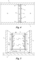
- the Fig. 4 and 5 show the result of a further step of the method, which is carried out after the assembly of the first and third angle profiles 4 1 , 4 3 :
- a first formwork 5 1 is attached to the first and third angle profiles 4 1 , 4 3 .
- the first and third angle profiles 4 1 , 4 3 thus jointly determine the position, ie the position and the alignment, of the first formwork 5 1 and subsequently the first formwork 5 1 determines the position of the front side 1 V ( Fig. 7 ) of the concrete wall 1 to be produced itself. Since this position relative to the existing walls 2, 3 is generally not arbitrary but precisely planned, an optional step can be carried out prior to the steps of mounting the angle profiles 4 i . In this prior step, the courses of those four edges K are determined which, during production, are to enclose the front and rear sides 1 V , 1 R of the concrete wall 1 with the first and second existing walls 2, 3, respectively, and of which two in Fig. 7 These four courses can optionally be marked or sketched on the existing walls 2, 3; in any case, during assembly, one of the angle profiles 4 i is mounted along each course, thereby ultimately ensuring that the concrete wall 1 is produced in the planned position.
- Fig. 6 shows the result of a further step of the method: After mounting the second and fourth angle profiles 4 2 , 4 4 , a second formwork 5 2 is attached to the second and fourth angle profiles 4 1 , 4 3 . It is understood that the second formwork 5 2 can be attached before, after or at most simultaneously with the first formwork 5 1 .
- one or both formworks 5 j can be screwed, riveted, nailed or similar to the respective angle profiles 4 i .
- one or both formworks 5 j can be pressed against the angle profiles 4 i with (here: one or) more supports 7 and/or both formworks 5 j can be anchored to one another using formwork anchors 8 and thus also pressed against the angle profiles 4 i .
- the space 9 formed by the formwork 5j, the angle profiles 4i and the existing walls 2, 3 is poured with liquid concrete and allowed to harden to form the concrete wall 1.
- connecting reinforcements 10 in order to be cast into the concrete wall 1 during pouring and to provide a firm connection to the existing walls 2,3.
- further reinforcements (not shown) for the concrete wall 1 are introduced into the space 9 mentioned before pouring.
- the formwork system 6 optionally comprises one or two further angle profiles 4 i , ie a fifth and/or a sixth angle profile 4 5 , 4 6 , of which the one in Fig. 4 left (and in Fig. 5 front) sixth angle profile 4 6 is shown in dashed lines.
- the fifth angle profile 4 5 is mounted along a line of intersection with a surface spanned by the first and third angle profiles 4 1 , 4 3 - i.e., between the first and third angle profiles 4 1 , 4 3 - on the floor 11 between the two existing walls 2, 3;
- the sixth angle profile 4 6 is mounted in a similar manner along a line of intersection with a surface spanned by the second and fourth angle profiles 4 2 , 4 4 - i.e., between the second and the fourth angle profile 4 2 , 4 4 - mounted on the floor 11 between the two existing walls 2, 3.
- the first formwork 5 1 is then attached to the fifth angle profile 4 5 or the second formwork 5 2 to the sixth angle profile 4 6 .
- Formwork 5 j for concrete walls 1 are available in several different widths BS ( Fig. 4 ), e.g. 2.4 m, 2.8 m, 3.2 m etc., and heights HS ( Fig. 5 ), e.g. 2.7 m, 3.3 m etc.
- the widths BS are adapted to the mutual distances A between adjacent load-bearing walls (here: existing walls 2, 3) that are usual in concrete construction; the widths BS of the formwork 5 j are slightly smaller than the distances A, which are e.g. 2.45 m, 2.85 m, 3.25 m etc., in order to be able to easily insert the formwork 5 j between the existing walls 2, 3.
- the heights HS of the formwork 5 j are adapted to typical storey heights G of e.g. 2.75 m, 3.35 m etc., i.e. again slightly smaller.
- the first, second, third and fourth angle profiles 4 1 , 4 2 , 4 3 , 4 4 each have a length PL 1 , PL 2 , PL 3 , PL 4 , which corresponds to a height HS 1 , HS 2 of the formwork 5 1 , 5 2 to be attached to them. In this way, no gaps remain between the existing walls 2, 3 and the formwork 5 j attached to them via the angle profiles 4 i . If angle profiles 4 5 , 4 6 are also mounted on the floor 11, for the same reason they preferably each have a length PL 5 , PL 6 , which corresponds to the width BS of the formwork 5 j to be attached to them.
- all angle profiles 4 i each have leg lengths SL which lead to a sufficient overlap of e.g. 20 mm or more with the formwork 5 j attached to them.
- angle profiles 4 i with a larger leg length SL of at least one leg S 1 , S 2 can be used if one of the existing walls 2, 3 or the floor 11 is uneven or inclined.
- Fig. 7 the optional supports 7 and/or formwork anchors 6 are removed, the formwork 5 j is removed and optionally the angle profiles 4 i are unscrewed or loosened and, if necessary, tapped with a hammer.
- the formwork system 6 can then be reused.
- the two existing walls 2, 3 are parallel to one another. It goes without saying that this is not necessary; the two existing walls 2, 3 could alternatively form an acute angle ⁇ with one another, for example.
- the concrete wall 1 is also shown at a right angle to the two existing walls 2, 3. This is also not mandatory; the concrete wall 1 could extend at an angle to the existing walls 2, 3 from the first to the second existing wall 2, 3.
- the angle profiles 4 i are optionally not right-angled; instead, their two legs S 1 , S 2 preferably form an angle ⁇ which corresponds to the respective angle of the edges K between the concrete wall 1 to be constructed and the existing walls 2, 3.
- the formwork 5 j is flat. This is also not mandatory.
- at least one of the formwork 5 j could be curved and/or have an angular shape, particularly when viewed from above.
- the angle profiles 4 1 , 4 2 , 4 3 , 4 4 are not all mounted parallel and perpendicular to one another, but rather adapted to the required position of the formwork 5 j on the existing walls 2, 3.
- the same applies to the optional angle profiles 4 5 , 4 6 which are mounted accordingly on the floor 11.
Landscapes
- Engineering & Computer Science (AREA)
- Architecture (AREA)
- Mechanical Engineering (AREA)
- Civil Engineering (AREA)
- Structural Engineering (AREA)
- Forms Removed On Construction Sites Or Auxiliary Members Thereof (AREA)
Claims (8)
- Procédé de fabrication d'un mur en béton (1) s'étendant d'un premier vers un deuxième mur existant (2, 3) à l'aide d'un premier coffrage (51) pour le côté avant (1V) du mur en béton (1) et d'un deuxième coffrage (52) pour le côté arrière (1R) du mur en béton (1) avec les étapes suivantes dans un ordre quelconque dans la mesure où cela n'est pas indiqué autrement :le montage d'un premier et d'un deuxième profilé d'angle (41, 42) sur le premier mur existant (2), où le premier profilé d'angle (4i) a une longueur (PL1), laquelle correspond à une hauteur (HS) du premier coffrage (51), et le deuxième profilé d'angle (42) a une longueur (PL2), laquelle correspond à une hauteur (HS) du deuxième coffrage (52) ;le montage d'un troisième et d'un quatrième profilé d'angle (43, 44) sur le deuxième mur existant (3), où le troisième profilé d'angle (43) a une longueur (PL3) , laquelle correspond à la hauteur (HS) du premier coffrage (51), et le quatrième profilé d'angle (44) a une longueur (PL4), laquelle correspond à la hauteur (HS) du deuxième coffrage (52) ;après le montage des premier et troisième profilés d'angle (41, 43), la fixation du premier coffrage (51) sur le premier et le troisième profilé d'angle (41, 43) ;après le montage des deuxième et quatrième profilés d'angle (42, 44), la fixation du deuxième coffrage (52) sur le deuxième et le quatrième profilé d'angle (42, 44) ;après la fixation des coffrages (5j), le remplissage de l'espace (9) formé par les coffrages (5j), les profilés d'angle (4i) et les murs existants (2, 3) avec du béton liquide et le durcissement pour former le mur en béton (1).
- Procédé selon la revendication 1, caractérisé par l'étape supplémentaire effectuée avant le montage des profilés d'angle (4i) : la détermination des tracés de celles quatre arêtes (K), qui les côtés avant et arrière (1V, 1R) du mur en béton (1) lors de la fabrication doivent entourer avec le premier et le deuxième mur existant (2, 3), où un profilé d'angle (4i) est monté lors du montage le long de chaque tracé déterminé .
- Procédé selon la revendication 1 ou 2, caractérisé en ce que les premier et deuxième profilés d'angle (41, 42) sont orientés lors du montage de telle manière que leurs flancs de profilé (S1, S2) adjacents au premier mur existant (2) sont opposés l'un à l'autre, et les troisième et quatrième profilés (43, 44) sont orientés de telle manière que leurs flancs de profilé (S1, S2) adjacents au deuxième mur existant (3) sont opposés l'un à l'autre.
- Procédé selon l'une des revendications 1 à 3, caractérisé en ce que les profilés d'angle (4i) sont vissés lors du montage sur le mur existant (2, 3) respectif.
- Procédé selon l'une des revendications 1 à 4, caractérisé en ce que les premier et deuxième coffrages (51, 52) lors de la fixation sont vissés sur les profilés d'angle (4i) respectifs.
- Procédé selon l'une des revendications 1 à 5, caractérisé en ce que le premier et/ou le deuxième coffrage (51, 52), lors de la fixation, sont pressés avec un ou plusieurs supports (7) contre les profilés d'angle (4i) respectifs et/ou les deux coffrages (5j) sont ancrés l'un à l'autre avec des ancrages de coffrage (8).
- Procédé selon l'une des revendications 1 à 6, caractérisé par les étapes supplémentaires effectuées avant la fixation des premier et deuxième coffrages (51, 52) :
le montage d'un cinquième profilé d'angle (45) sur le sol (11) entre le premier et le deuxième mur existant (2, 3) le long d'une ligne d'intersection avec une face étirée par le premier et le troisième profilé d'angle (41, 43) et le montage d'un sixième profilé d'angle (46) sur le sol (11) entre le premier et le deuxième mur existant (2, 3) le long d'une ligne d'intersection avec une face étirée par le deuxième et le quatrième profilé d'angle (42, 44), où, lors des étapes de fixation, le premier coffrage (51) est en outre fixé au cinquième profilé d'angle (45) et le deuxième coffrage (52) est en outre fixé au sixième profilé d'angle (46). - Procédé selon l'une des revendications 1 à 7, caractérisé par l'étape effectuée avant le remplissage :
mise en place d'une armature pour le mur en béton (1) dans ledit espace (9).
Priority Applications (1)
| Application Number | Priority Date | Filing Date | Title |
|---|---|---|---|
| PCT/AT2023/060303 WO2024081980A1 (fr) | 2022-10-17 | 2023-08-31 | Procédé et système de coffrage pour la fabrication d'une paroi en béton |
Applications Claiming Priority (1)
| Application Number | Priority Date | Filing Date | Title |
|---|---|---|---|
| AT1962022 | 2022-10-17 |
Publications (2)
| Publication Number | Publication Date |
|---|---|
| EP4357554A1 EP4357554A1 (fr) | 2024-04-24 |
| EP4357554B1 true EP4357554B1 (fr) | 2025-02-12 |
Family
ID=85251641
Family Applications (1)
| Application Number | Title | Priority Date | Filing Date |
|---|---|---|---|
| EP23156720.7A Active EP4357554B1 (fr) | 2022-10-17 | 2023-02-15 | Procédé et système de coffrage pour la fabrication d'une paroi en béton |
Country Status (1)
| Country | Link |
|---|---|
| EP (1) | EP4357554B1 (fr) |
Family Cites Families (6)
| Publication number | Priority date | Publication date | Assignee | Title |
|---|---|---|---|---|
| DE1784727A1 (de) * | 1968-09-11 | 1971-08-19 | Kallenbach Hans Erich | Verfahren zur Herstellung von Fliesen- oder dergleichen Trennwaenden und Vorrichtung zur Durchfuehrung des Verfahrens |
| KR20120002152A (ko) * | 2010-06-30 | 2012-01-05 | 강선중 | 거푸집 간격 유지구 |
| CO2016005799A1 (es) * | 2016-12-26 | 2018-07-10 | Carrascal Domingo De Guzman Claro | Mecanismo de formaleta |
| CN110284634B (zh) * | 2019-06-03 | 2021-05-07 | 上海港城建筑安装工程有限公司 | 一种保温墙浇筑成型施工工艺 |
| CN110409801B (zh) * | 2019-08-02 | 2024-11-29 | 中建四局华南建设有限公司 | 一种双层大角度倾斜轻质混凝土外隔墙施工方法及结构 |
| CN112962831B (zh) * | 2021-02-09 | 2022-12-16 | 天造机器人科技(广东)有限公司 | 基于机器人的内墙现浇模板快速安装方法 |
-
2023
- 2023-02-15 EP EP23156720.7A patent/EP4357554B1/fr active Active
Also Published As
| Publication number | Publication date |
|---|---|
| EP4357554A1 (fr) | 2024-04-24 |
Similar Documents
| Publication | Publication Date | Title |
|---|---|---|
| EP3384108B1 (fr) | Pièce de coffrage et coffrage de dalles comprenant une telle pièce de coffrage | |
| WO2018058166A1 (fr) | Dispositif de liaison servant à relier des éléments préfabriqués à paroi mince et éléments préfabriqués équipés de ce dispositif | |
| EP2268874A1 (fr) | Clameau pour la fixation de coffrages pour poutres en béton | |
| EP4357554B1 (fr) | Procédé et système de coffrage pour la fabrication d'une paroi en béton | |
| DE202011004223U1 (de) | Bewehrungsrahmen für eine Betonplatte | |
| DE102017206316B3 (de) | Schalungselement | |
| WO2024081980A1 (fr) | Procédé et système de coffrage pour la fabrication d'une paroi en béton | |
| DE2829941C3 (de) | Vorrictung zum Verbinden von Stahlbewehrungen | |
| DE2319190A1 (de) | Vorrichtung zur herstellung von ausnehmungen in gussbeton | |
| DE102007000866A1 (de) | Universalkonsole | |
| DE19720637C1 (de) | Verfahren zur Herstellung eines Bauteils aus Stahlbeton und Schalung zur Durchführung des Verfahrens | |
| AT507153B1 (de) | Eckelement zur verbindung von holzbalken für schalungen der erforderlichen aussparungen in betonwänden | |
| DD290925A5 (de) | Justierbares kopfplatten-zwischenbauteil | |
| EP3561199A1 (fr) | Élément de raccordement pour coffrages et procédé de raccordement du coffrage | |
| EP4640973A1 (fr) | Kit pour une construction de parapet sur un bâtiment, construction de parapet et methode de construction | |
| DE102005036881B4 (de) | Vorrichtung zum Erstellen einer Dehnfuge | |
| DE9311710U1 (de) | Schalung zum Herstellen einer Betonplatte | |
| DE102016103981A1 (de) | Schalungselement | |
| EP0392628B1 (fr) | Coffrage pour parois à couler, et support vertical pour ce coffrage | |
| DE202021102400U1 (de) | Schalungselement und Schalungssystem mit einem Schalungselement | |
| EP1995394A2 (fr) | Elément de compensation pour coffrages | |
| DE10007451A1 (de) | Montageträgersystem | |
| DE3506140A1 (de) | Plattenverankerungssystem | |
| DE102017206317A1 (de) | Schalungselement | |
| DE202017102195U1 (de) | Schalungselement |
Legal Events
| Date | Code | Title | Description |
|---|---|---|---|
| PUAI | Public reference made under article 153(3) epc to a published international application that has entered the european phase |
Free format text: ORIGINAL CODE: 0009012 |
|
| STAA | Information on the status of an ep patent application or granted ep patent |
Free format text: STATUS: REQUEST FOR EXAMINATION WAS MADE |
|
| 17P | Request for examination filed |
Effective date: 20231002 |
|
| AK | Designated contracting states |
Kind code of ref document: A1 Designated state(s): AL AT BE BG CH CY CZ DE DK EE ES FI FR GB GR HR HU IE IS IT LI LT LU LV MC ME MK MT NL NO PL PT RO RS SE SI SK SM TR |
|
| GRAP | Despatch of communication of intention to grant a patent |
Free format text: ORIGINAL CODE: EPIDOSNIGR1 |
|
| STAA | Information on the status of an ep patent application or granted ep patent |
Free format text: STATUS: GRANT OF PATENT IS INTENDED |
|
| INTG | Intention to grant announced |
Effective date: 20240604 |
|
| GRAS | Grant fee paid |
Free format text: ORIGINAL CODE: EPIDOSNIGR3 |
|
| GRAA | (expected) grant |
Free format text: ORIGINAL CODE: 0009210 |
|
| STAA | Information on the status of an ep patent application or granted ep patent |
Free format text: STATUS: THE PATENT HAS BEEN GRANTED |
|
| AK | Designated contracting states |
Kind code of ref document: B1 Designated state(s): AL AT BE BG CH CY CZ DE DK EE ES FI FR GB GR HR HU IE IS IT LI LT LU LV MC ME MK MT NL NO PL PT RO RS SE SI SK SM TR |
|
| REG | Reference to a national code |
Ref country code: GB Ref legal event code: FG4D Free format text: NOT ENGLISH |
|
| REG | Reference to a national code |
Ref country code: CH Ref legal event code: EP |
|
| REG | Reference to a national code |
Ref country code: DE Ref legal event code: R096 Ref document number: 502023000543 Country of ref document: DE |
|
| REG | Reference to a national code |
Ref country code: IE Ref legal event code: FG4D Free format text: LANGUAGE OF EP DOCUMENT: GERMAN |
|
| REG | Reference to a national code |
Ref country code: NL Ref legal event code: MP Effective date: 20250212 |
|
| PG25 | Lapsed in a contracting state [announced via postgrant information from national office to epo] |
Ref country code: RS Free format text: LAPSE BECAUSE OF FAILURE TO SUBMIT A TRANSLATION OF THE DESCRIPTION OR TO PAY THE FEE WITHIN THE PRESCRIBED TIME-LIMIT Effective date: 20250512 |
|
| PG25 | Lapsed in a contracting state [announced via postgrant information from national office to epo] |
Ref country code: FI Free format text: LAPSE BECAUSE OF FAILURE TO SUBMIT A TRANSLATION OF THE DESCRIPTION OR TO PAY THE FEE WITHIN THE PRESCRIBED TIME-LIMIT Effective date: 20250212 |
|
| PG25 | Lapsed in a contracting state [announced via postgrant information from national office to epo] |
Ref country code: PL Free format text: LAPSE BECAUSE OF FAILURE TO SUBMIT A TRANSLATION OF THE DESCRIPTION OR TO PAY THE FEE WITHIN THE PRESCRIBED TIME-LIMIT Effective date: 20250212 |
|
| PG25 | Lapsed in a contracting state [announced via postgrant information from national office to epo] |
Ref country code: ES Free format text: LAPSE BECAUSE OF FAILURE TO SUBMIT A TRANSLATION OF THE DESCRIPTION OR TO PAY THE FEE WITHIN THE PRESCRIBED TIME-LIMIT Effective date: 20250212 |
|
| REG | Reference to a national code |
Ref country code: LT Ref legal event code: MG9D |
|
| PG25 | Lapsed in a contracting state [announced via postgrant information from national office to epo] |
Ref country code: IS Free format text: LAPSE BECAUSE OF FAILURE TO SUBMIT A TRANSLATION OF THE DESCRIPTION OR TO PAY THE FEE WITHIN THE PRESCRIBED TIME-LIMIT Effective date: 20250612 Ref country code: NO Free format text: LAPSE BECAUSE OF FAILURE TO SUBMIT A TRANSLATION OF THE DESCRIPTION OR TO PAY THE FEE WITHIN THE PRESCRIBED TIME-LIMIT Effective date: 20250512 |
|
| PG25 | Lapsed in a contracting state [announced via postgrant information from national office to epo] |
Ref country code: NL Free format text: LAPSE BECAUSE OF FAILURE TO SUBMIT A TRANSLATION OF THE DESCRIPTION OR TO PAY THE FEE WITHIN THE PRESCRIBED TIME-LIMIT Effective date: 20250212 |
|
| PG25 | Lapsed in a contracting state [announced via postgrant information from national office to epo] |
Ref country code: HR Free format text: LAPSE BECAUSE OF FAILURE TO SUBMIT A TRANSLATION OF THE DESCRIPTION OR TO PAY THE FEE WITHIN THE PRESCRIBED TIME-LIMIT Effective date: 20250212 |
|
| PG25 | Lapsed in a contracting state [announced via postgrant information from national office to epo] |
Ref country code: PT Free format text: LAPSE BECAUSE OF FAILURE TO SUBMIT A TRANSLATION OF THE DESCRIPTION OR TO PAY THE FEE WITHIN THE PRESCRIBED TIME-LIMIT Effective date: 20250612 Ref country code: LV Free format text: LAPSE BECAUSE OF FAILURE TO SUBMIT A TRANSLATION OF THE DESCRIPTION OR TO PAY THE FEE WITHIN THE PRESCRIBED TIME-LIMIT Effective date: 20250212 |
|
| PG25 | Lapsed in a contracting state [announced via postgrant information from national office to epo] |
Ref country code: BG Free format text: LAPSE BECAUSE OF FAILURE TO SUBMIT A TRANSLATION OF THE DESCRIPTION OR TO PAY THE FEE WITHIN THE PRESCRIBED TIME-LIMIT Effective date: 20250212 Ref country code: GR Free format text: LAPSE BECAUSE OF FAILURE TO SUBMIT A TRANSLATION OF THE DESCRIPTION OR TO PAY THE FEE WITHIN THE PRESCRIBED TIME-LIMIT Effective date: 20250513 |
|
| PG25 | Lapsed in a contracting state [announced via postgrant information from national office to epo] |
Ref country code: SE Free format text: LAPSE BECAUSE OF FAILURE TO SUBMIT A TRANSLATION OF THE DESCRIPTION OR TO PAY THE FEE WITHIN THE PRESCRIBED TIME-LIMIT Effective date: 20250212 |
|
| PG25 | Lapsed in a contracting state [announced via postgrant information from national office to epo] |
Ref country code: SM Free format text: LAPSE BECAUSE OF FAILURE TO SUBMIT A TRANSLATION OF THE DESCRIPTION OR TO PAY THE FEE WITHIN THE PRESCRIBED TIME-LIMIT Effective date: 20250212 |
|
| PG25 | Lapsed in a contracting state [announced via postgrant information from national office to epo] |
Ref country code: DK Free format text: LAPSE BECAUSE OF FAILURE TO SUBMIT A TRANSLATION OF THE DESCRIPTION OR TO PAY THE FEE WITHIN THE PRESCRIBED TIME-LIMIT Effective date: 20250212 |
|
| PG25 | Lapsed in a contracting state [announced via postgrant information from national office to epo] |
Ref country code: LU Free format text: LAPSE BECAUSE OF NON-PAYMENT OF DUE FEES Effective date: 20250215 Ref country code: IT Free format text: LAPSE BECAUSE OF FAILURE TO SUBMIT A TRANSLATION OF THE DESCRIPTION OR TO PAY THE FEE WITHIN THE PRESCRIBED TIME-LIMIT Effective date: 20250212 |
|
| PG25 | Lapsed in a contracting state [announced via postgrant information from national office to epo] |
Ref country code: EE Free format text: LAPSE BECAUSE OF FAILURE TO SUBMIT A TRANSLATION OF THE DESCRIPTION OR TO PAY THE FEE WITHIN THE PRESCRIBED TIME-LIMIT Effective date: 20250212 Ref country code: CZ Free format text: LAPSE BECAUSE OF FAILURE TO SUBMIT A TRANSLATION OF THE DESCRIPTION OR TO PAY THE FEE WITHIN THE PRESCRIBED TIME-LIMIT Effective date: 20250212 |
|
| PG25 | Lapsed in a contracting state [announced via postgrant information from national office to epo] |
Ref country code: RO Free format text: LAPSE BECAUSE OF FAILURE TO SUBMIT A TRANSLATION OF THE DESCRIPTION OR TO PAY THE FEE WITHIN THE PRESCRIBED TIME-LIMIT Effective date: 20250212 |
|
| PG25 | Lapsed in a contracting state [announced via postgrant information from national office to epo] |
Ref country code: SK Free format text: LAPSE BECAUSE OF FAILURE TO SUBMIT A TRANSLATION OF THE DESCRIPTION OR TO PAY THE FEE WITHIN THE PRESCRIBED TIME-LIMIT Effective date: 20250212 |
|
| REG | Reference to a national code |
Ref country code: DE Ref legal event code: R097 Ref document number: 502023000543 Country of ref document: DE |
|
| REG | Reference to a national code |
Ref country code: BE Ref legal event code: MM Effective date: 20250228 |
|
| PLBE | No opposition filed within time limit |
Free format text: ORIGINAL CODE: 0009261 |
|
| STAA | Information on the status of an ep patent application or granted ep patent |
Free format text: STATUS: NO OPPOSITION FILED WITHIN TIME LIMIT |
|
| PG25 | Lapsed in a contracting state [announced via postgrant information from national office to epo] |
Ref country code: MC Free format text: LAPSE BECAUSE OF FAILURE TO SUBMIT A TRANSLATION OF THE DESCRIPTION OR TO PAY THE FEE WITHIN THE PRESCRIBED TIME-LIMIT Effective date: 20250212 |
|
| PG25 | Lapsed in a contracting state [announced via postgrant information from national office to epo] |
Ref country code: FR Free format text: LAPSE BECAUSE OF NON-PAYMENT OF DUE FEES Effective date: 20250412 |
|
| PG25 | Lapsed in a contracting state [announced via postgrant information from national office to epo] |
Ref country code: BE Free format text: LAPSE BECAUSE OF NON-PAYMENT OF DUE FEES Effective date: 20250228 |
|
| PG25 | Lapsed in a contracting state [announced via postgrant information from national office to epo] |
Ref country code: IE Free format text: LAPSE BECAUSE OF NON-PAYMENT OF DUE FEES Effective date: 20250215 |
|
| 26N | No opposition filed |
Effective date: 20251113 |
|
| PGFP | Annual fee paid to national office [announced via postgrant information from national office to epo] |
Ref country code: DE Payment date: 20260217 Year of fee payment: 4 |
|
| PGFP | Annual fee paid to national office [announced via postgrant information from national office to epo] |
Ref country code: AT Payment date: 20260301 Year of fee payment: 4 |