EP1995394A2 - Elément de compensation pour coffrages - Google Patents
Elément de compensation pour coffrages Download PDFInfo
- Publication number
- EP1995394A2 EP1995394A2 EP20080009468 EP08009468A EP1995394A2 EP 1995394 A2 EP1995394 A2 EP 1995394A2 EP 20080009468 EP20080009468 EP 20080009468 EP 08009468 A EP08009468 A EP 08009468A EP 1995394 A2 EP1995394 A2 EP 1995394A2
- Authority
- EP
- European Patent Office
- Prior art keywords
- compensation
- segments
- compensating
- formwork
- compensation element
- Prior art date
- Legal status (The legal status is an assumption and is not a legal conclusion. Google has not performed a legal analysis and makes no representation as to the accuracy of the status listed.)
- Withdrawn
Links
- 238000009415 formwork Methods 0.000 title claims description 45
- 239000004567 concrete Substances 0.000 claims abstract description 19
- 229910052782 aluminium Inorganic materials 0.000 claims abstract description 4
- XAGFODPZIPBFFR-UHFFFAOYSA-N aluminium Chemical compound [Al] XAGFODPZIPBFFR-UHFFFAOYSA-N 0.000 claims abstract description 4
- 229910052751 metal Inorganic materials 0.000 claims description 2
- 239000002184 metal Substances 0.000 claims description 2
- 238000009416 shuttering Methods 0.000 abstract description 2
- 239000004411 aluminium Substances 0.000 abstract 1
- 238000010276 construction Methods 0.000 description 7
- 239000000463 material Substances 0.000 description 2
- 229910000831 Steel Inorganic materials 0.000 description 1
- 230000001419 dependent effect Effects 0.000 description 1
- 238000003780 insertion Methods 0.000 description 1
- 230000037431 insertion Effects 0.000 description 1
- 239000007788 liquid Substances 0.000 description 1
- 238000000034 method Methods 0.000 description 1
- 239000011150 reinforced concrete Substances 0.000 description 1
- 238000007711 solidification Methods 0.000 description 1
- 230000008023 solidification Effects 0.000 description 1
- 239000010959 steel Substances 0.000 description 1
Images


Classifications
-
- E—FIXED CONSTRUCTIONS
- E04—BUILDING
- E04G—SCAFFOLDING; FORMS; SHUTTERING; BUILDING IMPLEMENTS OR AIDS, OR THEIR USE; HANDLING BUILDING MATERIALS ON THE SITE; REPAIRING, BREAKING-UP OR OTHER WORK ON EXISTING BUILDINGS
- E04G11/00—Forms, shutterings, or falsework for making walls, floors, ceilings, or roofs
- E04G11/06—Forms, shutterings, or falsework for making walls, floors, ceilings, or roofs for walls, e.g. curved end panels for wall shutterings; filler elements for wall shutterings; shutterings for vertical ducts
- E04G11/08—Forms, which are completely dismantled after setting of the concrete and re-built for next pouring
- E04G11/087—Fill-in form panels in the plane of two adjacent forms
Definitions
- the present invention relates to a compensating element for formwork, in particular concrete formwork.
- Formwork is often used in the construction of concrete structures.
- such formworks are constructed from individual formwork elements. They are used on construction sites of various sizes to define limited volumes in the construction of (steel) concrete shell buildings by formwork surfaces, which are then filled with liquid concrete. After solidification of the concrete shuttering elements are then usually removed again, whereupon they are usually reusable for the construction of other formwork.
- walls, columns, foundations, shafts and the like of concrete and reinforced concrete can be produced in the manner mentioned.
- the present invention has for its object to overcome the disadvantages of the prior art.
- a compensation element for formwork especially concrete formwork, which is characterized in that it is adjustable to different widths.
- the width of the compensating element according to the invention Due to the variability in terms of the width of the compensating element according to the invention, this can be adapted to the widest range of requirements. It is possible to differentiate with a single element in a simple way To bridge distances between the formwork elements of a formwork.
- this has two compensation segments, which preferably each have at least one substantially flat side surface, which preferably lie in one insertion position on a plane.
- the compensation segments are held at different distances from each other and are preferably releasably connectable to each other. This allows the compensation element to be set to different widths.
- the compensating element has an actuating element, by means of which the compensating segments can be held at different distances from one another, wherein the compensating segments are preferably detachably connectable to the adjusting element.
- the actuator is a, preferably elongated, profile, which preferably has a plurality of ribs of different width. By arranging such ribs of different width, the compensating element can be adjusted in a simple manner to different widths by the balancing segments are each brought into abutment with one outer edge with the opposite edges of a rib of suitable width.
- the actuator preferably fixable between the compensation segments.
- the control element with the two compensation segments can be screwed.
- the compensation segments in the mounted state together with an end face of the adjusting element form a substantially flat surface, which is preferably smooth.
- the compensation element according to the invention has at least partially a smooth surface.
- it is at least partially made of metal, preferably aluminum.
- this is at least partially made of plastic, preferably coated plastic.
- the materials mentioned all have a smooth surface structure, whereby the structures to be created receive particularly smooth, visually appealing surfaces.
- the compensating element according to the invention can be used several times. This saves material costs and is often not possible with the use of squared lumber, since these must be partially broken away from the hardened concrete, as they adhere strongly to the concrete due to their uneven surface. In addition, it is unlikely that squared timbers randomly return to the required width the next time they are used.
- the compensating segment according to the invention can be connected in a simple manner to the formwork elements of a formwork such that the flat surface of the compensating element is flush with one or two formwork elements, in particular their formwork panels. This creates an overall flat formwork surface. This is usually very difficult to implement when installing squared lumber between formwork elements. Often the square timber is either beyond the formwork surface or it is under. This naturally causes unevenness in the surface of the concrete structures to be created.
- the present invention further relates to a kit for assembling a compensating element, in particular a compensating element according to the invention, comprising at least two compensating segments and at least one adjusting element, by means of which the compensating segments can be held at different distances from each other. Compensation segments and actuator are already described above.
- the present invention further relates to the use of a compensating element according to the invention for adapting formworks to different widths of structures to be constructed.
- the compensation element is positioned between individual formwork elements of a formwork.
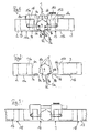
- FIG. 1 shows a plan view of an inventive compensating element 1.
- the compensating element 1 has two balancing segments 2, 3, wherein the two balancing segments 2, 3 are formed differently wide. Between the compensating segments 2, 3 there is an elongated profile 4 functioning as an adjusting element, which has six ribs 5, 5a of different width.
- the compensating segments 2, 3 are substantially formed as elongated cuboids, wherein each side surface 6a, 6b is L-shaped. This results in each case a spring-like longitudinal rib 7a, 7b on a longitudinal edge of the cuboid base body.
- the height (thickness) of these longitudinal ribs 7 a, 7 b corresponds to the height of the ribs 5, 5 a of the profile 4.
- a certain rib 5a of the profile 4 was selected and clamped between the longitudinal ribs 7a and 7b.
- the end faces 8a, 8b of the longitudinal ribs 7a, 7b were brought into abutment with the side surfaces (flanks) 9a, 9b of the rib 5a.
- the rib 5a forms, like all the other ribs 5, two grooves 10a, 10b, in which the longitudinal ribs 7a, 7b, which act as a kind of springs for the grooves 10a, 10b brought.
- the flat surface 13, when used in formwork, is used as the side that comes in contact with the concrete. Characterized in that both the profile 4 and the balancing segments 2 and 3 are made of aluminum, the entire surface, and thus the flat surface 13, formed completely smooth.
- the profile 4 is detachably connected to the compensation segments 2, 3.
- a bolt 14 is guided by side walls 15a and 15b and by a channel in the profile 4 and screwed to the inner side surfaces of the side walls 15a, 15b by means of a nut.
- the connection is supported by the fastening element 16, which has two clamp elements 16b connected by a bolt 16a.
- the fastening element serves primarily to stabilize the compensating element 1 by holding the surfaces 11a, 11b and 12 in one plane.
- FIG. 2 shows the compensating element 1 of FIG. 1 in disassembled state (like reference numerals designate like elements).
- the individual elements 2, 3, 4 can be used as a kit.
- This kit can also have other compensation segments of different widths.
- FIG. 3 shows the balancing segment 1 of FIG. 1 , integrated in a formwork.
- the compensation segment 1 is introduced between two formwork elements 17 and ends flush with these, so that a flat surface 18 is formed, which is used as a concrete side surface of the formwork.
- the element 1 can be connected to the formwork elements, for example by brackets.
- FIG. 4 shows a kit 19 for assembling compensating elements of different widths.
- the kit 19 comprises two compensation segments 2 according to FIG FIG. 1 and two compensation segments 3, also according to FIG. 1 ,
- the width x of the side surface 11a of the compensation segment 2 is 30 centimeters and the width y of the side surface 11b of the compensation segment 3 is 35 centimeters.
- the widths z of the ribs 5 of the profile 4 are different and amount to one centimeter, two centimeters, three centimeters, four centimeters, five centimeters and six centimeters.
- compensation elements with widths of 61 centimeters to 76 centimeters, each in one-centimeter steps can be adjusted.
- FIG. 5 shows the perspective view of the compensating element 1 of FIG. 1 , Can be seen in this illustration, the flat surface 13, which is formed by the flush completion of the side surface 12 of the rib 5a with the side surfaces 11a and 11b of the balancing segments 2 and 3 respectively.
Landscapes
- Engineering & Computer Science (AREA)
- Architecture (AREA)
- Mechanical Engineering (AREA)
- Civil Engineering (AREA)
- Structural Engineering (AREA)
- Forms Removed On Construction Sites Or Auxiliary Members Thereof (AREA)
Applications Claiming Priority (1)
| Application Number | Priority Date | Filing Date | Title |
|---|---|---|---|
| DE200710024660 DE102007024660A1 (de) | 2007-05-25 | 2007-05-25 | Ausgleichselement für Schalungen |
Publications (1)
| Publication Number | Publication Date |
|---|---|
| EP1995394A2 true EP1995394A2 (fr) | 2008-11-26 |
Family
ID=39756640
Family Applications (1)
| Application Number | Title | Priority Date | Filing Date |
|---|---|---|---|
| EP20080009468 Withdrawn EP1995394A2 (fr) | 2007-05-25 | 2008-05-23 | Elément de compensation pour coffrages |
Country Status (2)
| Country | Link |
|---|---|
| EP (1) | EP1995394A2 (fr) |
| DE (1) | DE102007024660A1 (fr) |
Cited By (1)
| Publication number | Priority date | Publication date | Assignee | Title |
|---|---|---|---|---|
| WO2017054028A1 (fr) | 2015-09-30 | 2017-04-06 | Form 700 Pty Ltd | Ensemble panneau de coffrage |
Family Cites Families (2)
| Publication number | Priority date | Publication date | Assignee | Title |
|---|---|---|---|---|
| DE1952963A1 (de) * | 1969-10-21 | 1971-04-29 | Richard Lorenz | Schalvorrichtung |
| DE19502719C2 (de) * | 1995-01-28 | 1999-02-25 | August Wendler Ohg | Schalelement mit durch Rahmenbauweise formstabilisierter Schalhaut |
-
2007
- 2007-05-25 DE DE200710024660 patent/DE102007024660A1/de not_active Withdrawn
-
2008
- 2008-05-23 EP EP20080009468 patent/EP1995394A2/fr not_active Withdrawn
Cited By (6)
| Publication number | Priority date | Publication date | Assignee | Title |
|---|---|---|---|---|
| WO2017054028A1 (fr) | 2015-09-30 | 2017-04-06 | Form 700 Pty Ltd | Ensemble panneau de coffrage |
| CN108368705A (zh) * | 2015-09-30 | 2018-08-03 | 福姆700私人有限公司 | 模板面板装配件 |
| US20180266126A1 (en) * | 2015-09-30 | 2018-09-20 | Form 700 Pty Ltd | Formwork panel assembly |
| JP2018529862A (ja) * | 2015-09-30 | 2018-10-11 | フォーム 700 ピーティーワイ リミテッドForm 700 Pty Ltd | 型枠パネルアセンブリ |
| EP3356617A4 (fr) * | 2015-09-30 | 2019-06-26 | Form 700 Pty Ltd | Ensemble panneau de coffrage |
| US10584501B2 (en) * | 2015-09-30 | 2020-03-10 | Form 700 Pty Ltd | Formwork panel assembly with releasable connecting member and method of removing the formwork |
Also Published As
| Publication number | Publication date |
|---|---|
| DE102007024660A1 (de) | 2008-12-04 |
Similar Documents
| Publication | Publication Date | Title |
|---|---|---|
| EP3572198B1 (fr) | Coffrage central pour un système de coffrage destiné à bétonner un corps de cloche | |
| EP0641901A1 (fr) | Système de montage ou de construction pour une maison en bois | |
| EP0985074A1 (fr) | Element de decoffrage | |
| DE2534160A1 (de) | Schalung zum betonieren | |
| DE102014013559A1 (de) | Vorrichtung zum Abschalten einer zu verfüllenden Fuge | |
| DE102009047415A1 (de) | Anordnung mit Platten, insbesondere Gipskarton- und/oder Gipsfaserplatten für den Trockenbau, und mit einem Montagehilfselement sowie Montageverfahren hiermit | |
| EP1995394A2 (fr) | Elément de compensation pour coffrages | |
| DE202015105866U1 (de) | Abschalvorrichtung zur Abschalung von Fugen | |
| DE102016111211B4 (de) | Schalungssystem für die Errichtung niedriger Bauabschnitte aus Ortbeton | |
| DE3241424C2 (de) | Verbindungseinrichtung | |
| DE19800568C1 (de) | Aussparschalung | |
| DE102015118895B4 (de) | Abschalvorrichtung zur Abschalung von Fugen | |
| CH713190A2 (de) | Vorrichtung und Verfahren zur Verbindung von zwei Bauteilen in einer bestimmten relativen Ausrichtung sowie damit erstelltes Betonbauwerk. | |
| CH718328B1 (de) | Abschalleiste, Überdeckungsabschalung, Abschalungselement, Schalungsanordnung, Verfahren zum Aufbau einer Schalungsanordnung und Verfahren zum Herstellen einer Abschalleiste. | |
| EP4357554B1 (fr) | Procédé et système de coffrage pour la fabrication d'une paroi en béton | |
| AT507153B1 (de) | Eckelement zur verbindung von holzbalken für schalungen der erforderlichen aussparungen in betonwänden | |
| DE10320003A1 (de) | Positioniervorrichtung, Schalungseinheit und Wandschalung | |
| AT528551B1 (de) | Schalungselement, Schalungssystem und Verfahren zur Verschalung | |
| DE2548298C2 (de) | Verfahren und Hohlraumverschalungswand zum Bauen einer Hohlmauer | |
| DE4326934A1 (de) | Vorrichtung zum Bearbeiten, insbesondere Verputzen von Laibungen | |
| DE29915343U1 (de) | Stahlbetonteil zur Herstellung von Fundamenten für Bauwerke | |
| CH620260A5 (en) | Assembled shuttering for blocking out openings | |
| EP0675239B1 (fr) | Ensemble de blocs de construction | |
| WO2024081980A1 (fr) | Procédé et système de coffrage pour la fabrication d'une paroi en béton | |
| DE938987C (de) | Vorrichtung zur Herstellung von Bauwerken, insbesondere von Mauerwerken aus Schuettbeton u. dgl. |
Legal Events
| Date | Code | Title | Description |
|---|---|---|---|
| PUAI | Public reference made under article 153(3) epc to a published international application that has entered the european phase |
Free format text: ORIGINAL CODE: 0009012 |
|
| AK | Designated contracting states |
Kind code of ref document: A2 Designated state(s): AT BE BG CH CY CZ DE DK EE ES FI FR GB GR HR HU IE IS IT LI LT LU LV MC MT NL NO PL PT RO SE SI SK TR |
|
| AX | Request for extension of the european patent |
Extension state: AL BA MK RS |
|
| STAA | Information on the status of an ep patent application or granted ep patent |
Free format text: STATUS: THE APPLICATION IS DEEMED TO BE WITHDRAWN |
|
| 18D | Application deemed to be withdrawn |
Effective date: 20111201 |