EP4357621A2 - Composant de moteur à turbine à gaz composite à structure en treillis - Google Patents
Composant de moteur à turbine à gaz composite à structure en treillis Download PDFInfo
- Publication number
- EP4357621A2 EP4357621A2 EP24163069.8A EP24163069A EP4357621A2 EP 4357621 A2 EP4357621 A2 EP 4357621A2 EP 24163069 A EP24163069 A EP 24163069A EP 4357621 A2 EP4357621 A2 EP 4357621A2
- Authority
- EP
- European Patent Office
- Prior art keywords
- section
- airfoil
- lattice structure
- platform
- internal cavity
- Prior art date
- Legal status (The legal status is an assumption and is not a legal conclusion. Google has not performed a legal analysis and makes no representation as to the accuracy of the status listed.)
- Pending
Links
Images



Classifications
-
- B—PERFORMING OPERATIONS; TRANSPORTING
- B29—WORKING OF PLASTICS; WORKING OF SUBSTANCES IN A PLASTIC STATE IN GENERAL
- B29D—PRODUCING PARTICULAR ARTICLES FROM PLASTICS OR FROM SUBSTANCES IN A PLASTIC STATE
- B29D99/00—Subject matter not provided for in other groups of this subclass
- B29D99/0003—Producing profiled members, e.g. beams
- B29D99/0005—Producing noodles, i.e. composite gap fillers, characterised by their construction
-
- F—MECHANICAL ENGINEERING; LIGHTING; HEATING; WEAPONS; BLASTING
- F01—MACHINES OR ENGINES IN GENERAL; ENGINE PLANTS IN GENERAL; STEAM ENGINES
- F01D—NON-POSITIVE DISPLACEMENT MACHINES OR ENGINES, e.g. STEAM TURBINES
- F01D5/00—Blades; Blade-carrying members; Heating, heat-insulating, cooling or antivibration means on the blades or the members
- F01D5/12—Blades
- F01D5/14—Form or construction
- F01D5/147—Construction, i.e. structural features, e.g. of weight-saving hollow blades
-
- B—PERFORMING OPERATIONS; TRANSPORTING
- B33—ADDITIVE MANUFACTURING TECHNOLOGY
- B33Y—ADDITIVE MANUFACTURING, i.e. MANUFACTURING OF THREE-DIMENSIONAL [3D] OBJECTS BY ADDITIVE DEPOSITION, ADDITIVE AGGLOMERATION OR ADDITIVE LAYERING, e.g. BY 3D PRINTING, STEREOLITHOGRAPHY OR SELECTIVE LASER SINTERING
- B33Y80/00—Products made by additive manufacturing
-
- F—MECHANICAL ENGINEERING; LIGHTING; HEATING; WEAPONS; BLASTING
- F01—MACHINES OR ENGINES IN GENERAL; ENGINE PLANTS IN GENERAL; STEAM ENGINES
- F01D—NON-POSITIVE DISPLACEMENT MACHINES OR ENGINES, e.g. STEAM TURBINES
- F01D11/00—Preventing or minimising internal leakage of working-fluid, e.g. between stages
- F01D11/005—Sealing means between non relatively rotating elements
- F01D11/006—Sealing the gap between rotor blades or blades and rotor
- F01D11/008—Sealing the gap between rotor blades or blades and rotor by spacer elements between the blades, e.g. independent interblade platforms
-
- F—MECHANICAL ENGINEERING; LIGHTING; HEATING; WEAPONS; BLASTING
- F01—MACHINES OR ENGINES IN GENERAL; ENGINE PLANTS IN GENERAL; STEAM ENGINES
- F01D—NON-POSITIVE DISPLACEMENT MACHINES OR ENGINES, e.g. STEAM TURBINES
- F01D5/00—Blades; Blade-carrying members; Heating, heat-insulating, cooling or antivibration means on the blades or the members
- F01D5/12—Blades
- F01D5/14—Form or construction
- F01D5/141—Shape, i.e. outer, aerodynamic form
- F01D5/142—Shape, i.e. outer, aerodynamic form of the blades of successive rotor or stator blade-rows
- F01D5/143—Contour of the outer or inner working fluid flow path wall, i.e. shroud or hub contour
-
- F—MECHANICAL ENGINEERING; LIGHTING; HEATING; WEAPONS; BLASTING
- F01—MACHINES OR ENGINES IN GENERAL; ENGINE PLANTS IN GENERAL; STEAM ENGINES
- F01D—NON-POSITIVE DISPLACEMENT MACHINES OR ENGINES, e.g. STEAM TURBINES
- F01D5/00—Blades; Blade-carrying members; Heating, heat-insulating, cooling or antivibration means on the blades or the members
- F01D5/12—Blades
- F01D5/14—Form or construction
- F01D5/18—Hollow blades, i.e. blades with cooling or heating channels or cavities; Heating, heat-insulating or cooling means on blades
-
- F—MECHANICAL ENGINEERING; LIGHTING; HEATING; WEAPONS; BLASTING
- F01—MACHINES OR ENGINES IN GENERAL; ENGINE PLANTS IN GENERAL; STEAM ENGINES
- F01D—NON-POSITIVE DISPLACEMENT MACHINES OR ENGINES, e.g. STEAM TURBINES
- F01D5/00—Blades; Blade-carrying members; Heating, heat-insulating, cooling or antivibration means on the blades or the members
- F01D5/12—Blades
- F01D5/28—Selecting particular materials; Particular measures relating thereto; Measures against erosion or corrosion
- F01D5/282—Selecting composite materials, e.g. blades with reinforcing filaments
-
- F—MECHANICAL ENGINEERING; LIGHTING; HEATING; WEAPONS; BLASTING
- F04—POSITIVE - DISPLACEMENT MACHINES FOR LIQUIDS; PUMPS FOR LIQUIDS OR ELASTIC FLUIDS
- F04D—NON-POSITIVE-DISPLACEMENT PUMPS
- F04D29/00—Details, component parts, or accessories
- F04D29/26—Rotors specially for elastic fluids
- F04D29/32—Rotors specially for elastic fluids for axial flow pumps
- F04D29/321—Rotors specially for elastic fluids for axial flow pumps for axial flow compressors
- F04D29/324—Blades
-
- F—MECHANICAL ENGINEERING; LIGHTING; HEATING; WEAPONS; BLASTING
- F05—INDEXING SCHEMES RELATING TO ENGINES OR PUMPS IN VARIOUS SUBCLASSES OF CLASSES F01-F04
- F05D—INDEXING SCHEME FOR ASPECTS RELATING TO NON-POSITIVE-DISPLACEMENT MACHINES OR ENGINES, GAS-TURBINES OR JET-PROPULSION PLANTS
- F05D2220/00—Application
- F05D2220/30—Application in turbines
- F05D2220/32—Application in turbines in gas turbines
-
- F—MECHANICAL ENGINEERING; LIGHTING; HEATING; WEAPONS; BLASTING
- F05—INDEXING SCHEMES RELATING TO ENGINES OR PUMPS IN VARIOUS SUBCLASSES OF CLASSES F01-F04
- F05D—INDEXING SCHEME FOR ASPECTS RELATING TO NON-POSITIVE-DISPLACEMENT MACHINES OR ENGINES, GAS-TURBINES OR JET-PROPULSION PLANTS
- F05D2240/00—Components
- F05D2240/80—Platforms for stationary or moving blades
-
- F—MECHANICAL ENGINEERING; LIGHTING; HEATING; WEAPONS; BLASTING
- F05—INDEXING SCHEMES RELATING TO ENGINES OR PUMPS IN VARIOUS SUBCLASSES OF CLASSES F01-F04
- F05D—INDEXING SCHEME FOR ASPECTS RELATING TO NON-POSITIVE-DISPLACEMENT MACHINES OR ENGINES, GAS-TURBINES OR JET-PROPULSION PLANTS
- F05D2300/00—Materials; Properties thereof
- F05D2300/60—Properties or characteristics given to material by treatment or manufacturing
- F05D2300/601—Fabrics
- F05D2300/6012—Woven fabrics
-
- F—MECHANICAL ENGINEERING; LIGHTING; HEATING; WEAPONS; BLASTING
- F05—INDEXING SCHEMES RELATING TO ENGINES OR PUMPS IN VARIOUS SUBCLASSES OF CLASSES F01-F04
- F05D—INDEXING SCHEME FOR ASPECTS RELATING TO NON-POSITIVE-DISPLACEMENT MACHINES OR ENGINES, GAS-TURBINES OR JET-PROPULSION PLANTS
- F05D2300/00—Materials; Properties thereof
- F05D2300/60—Properties or characteristics given to material by treatment or manufacturing
- F05D2300/603—Composites; e.g. fibre-reinforced
-
- F—MECHANICAL ENGINEERING; LIGHTING; HEATING; WEAPONS; BLASTING
- F05—INDEXING SCHEMES RELATING TO ENGINES OR PUMPS IN VARIOUS SUBCLASSES OF CLASSES F01-F04
- F05D—INDEXING SCHEME FOR ASPECTS RELATING TO NON-POSITIVE-DISPLACEMENT MACHINES OR ENGINES, GAS-TURBINES OR JET-PROPULSION PLANTS
- F05D2300/00—Materials; Properties thereof
- F05D2300/60—Properties or characteristics given to material by treatment or manufacturing
- F05D2300/603—Composites; e.g. fibre-reinforced
- F05D2300/6033—Ceramic matrix composites [CMC]
-
- F—MECHANICAL ENGINEERING; LIGHTING; HEATING; WEAPONS; BLASTING
- F05—INDEXING SCHEMES RELATING TO ENGINES OR PUMPS IN VARIOUS SUBCLASSES OF CLASSES F01-F04
- F05D—INDEXING SCHEME FOR ASPECTS RELATING TO NON-POSITIVE-DISPLACEMENT MACHINES OR ENGINES, GAS-TURBINES OR JET-PROPULSION PLANTS
- F05D2300/00—Materials; Properties thereof
- F05D2300/60—Properties or characteristics given to material by treatment or manufacturing
- F05D2300/615—Filler
-
- Y—GENERAL TAGGING OF NEW TECHNOLOGICAL DEVELOPMENTS; GENERAL TAGGING OF CROSS-SECTIONAL TECHNOLOGIES SPANNING OVER SEVERAL SECTIONS OF THE IPC; TECHNICAL SUBJECTS COVERED BY FORMER USPC CROSS-REFERENCE ART COLLECTIONS [XRACs] AND DIGESTS
- Y02—TECHNOLOGIES OR APPLICATIONS FOR MITIGATION OR ADAPTATION AGAINST CLIMATE CHANGE
- Y02T—CLIMATE CHANGE MITIGATION TECHNOLOGIES RELATED TO TRANSPORTATION
- Y02T50/00—Aeronautics or air transport
- Y02T50/60—Efficient propulsion technologies, e.g. for aircraft
Definitions
- This disclosure relates to a gas turbine engine, and more particularly to a rotor assembly including composite components.
- Gas turbine engines can include a fan for propulsion air and to cool components.
- the fan also delivers air into a core engine where it is compressed.
- the compressed air is then delivered into a combustion section, where it is mixed with fuel and ignited.
- the combustion gas expands downstream over and drives turbine blades.
- Static vanes are positioned adjacent to the turbine blades to control the flow of the products of combustion.
- the gas turbine engine may include composite components formed from by ply layers.
- the ply layers may be arranged to define one or more voids or cavities. Fillers may be placed in the cavities and may be dimensioned to have a complementary geometry with the adjacent ply layers.
- An assembly for a gas turbine engine includes an airfoil that has an airfoil section extending from a root section.
- the airfoil section extends between a leading edge and a trailing edge in a chordwise direction and extending between a tip portion and the root section in a radial direction.
- the airfoil section defines a pressure side and a suction side separated in a thickness direction.
- a platform is dimensioned to receive a retention pin to mount the platform to a rotatable hub.
- At least one of the airfoil and the platform includes a plurality of composite layers that define an internal cavity.
- a lattice structure in the internal cavity extends between the plurality of composite layers.
- the lattice structure has a plurality of branches that extend from a plurality of nodes.
- the lattice structure is metallic.
- a volume of the internal cavity between surfaces of the plurality of composite layers that bound the internal cavity and surfaces of the lattice structure is hollow.
- the platform includes a bushing in the internal cavity.
- the bushing is dimensioned to receive the retention pin, and the lattice structure extends between the bushing and surfaces of the plurality of composite layers that bound the internal cavity.
- the plurality of composite layers include first and second sets of ply layers that define an outer periphery of the platform, and include a third set of ply layers that abut against the first and second sets of ply layers to surround a hollow cavity.
- the plurality of composite layers are arranged such that a cross section of the internal cavity has a deltoid shaped geometry.
- the airfoil section includes a sheath that has a first skin and a second skin joined together to define the pressure and suction sides of the airfoil section.
- the sheath receives a composite core comprising the plurality of composite layers.
- the first and second skins are metallic.
- the internal cavity is defined in the root section. At least one of the plurality of composite layers is dimensioned to loop around a bushing in the lattice structure.
- a perimeter of the internal cavity tapers towards the tip portion.
- a platform for a gas turbine engine includes a platform body that defines one or more slots between a plurality of flanges.
- the one or more slots are dimensioned to receive a respective flange of a hub, and the platform body includes a plurality of composite layers that join together to define an internal cavity.
- a lattice structure in the internal cavity that extends between the plurality of composite layers.
- the lattice structure includes a plurality of branches that extend from a plurality of nodes.
- the lattice structure is metallic, and the plurality of composite layers comprise carbon.
- the platform has a bushing in the internal cavity.
- the bushing is dimensioned to receive a retention pin to mount the platform, and the lattice structure extends between the bushing and surfaces of the plurality of composite layers that bound the internal cavity.
- the plurality of composite layers include first, second and third sets of ply layers.
- the first set of ply layers define a platform base dimensioned to extend between adjacent airfoils.
- the second set of ply layers extend from the first set of ply layers to define the plurality of flanges, and the third set of ply layers abut against the first and second layers to surround a passage that extends through the plurality of flanges.
- a gas turbine engine includes a fan section, a compressor section, a turbine section that drives the fan section and the compressor section, and a rotor assembly including a hub rotatable about an engine longitudinal axis.
- the hub has a plurality of flanges.
- An array of airfoils are circumferentially distributed about an outer periphery of the hub.
- Each one of the airfoils has an airfoil section that extends from a root section mounted to the hub.
- An array of platforms are mechanically attached to the hub.
- Each of the platforms have one or more slots defined by a plurality of flanges. The one or more slots are dimensioned to receive a respective one of the flanges of the hub.
- a plurality of retention pins extend through the flanges of the hub and through the plurality of flanges of a respective one of the platforms to mechanically attach the respective one of the platforms to the hub.
- a plurality of lattice structures in a plurality of internal cavities are defined by the rotor assembly. Each of the internal cavities are bounded by one or more composite layers.
- each of the lattice structures includes a plurality of branches that extend from a plurality of nodes.
- the fan section comprises the rotor assembly.
- At least one of the airfoil section and the root section comprises the one or more composite layers that define a respective one of the internal cavities.
- the one or more composite layers define external surfaces of the airfoil section.
- the array of platforms comprises the one or more composite layers that define a respective one of the internal cavities.
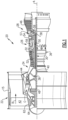
- FIG. 1 schematically illustrates a gas turbine engine 20.
- the gas turbine engine 20 is disclosed herein as a two-spool turbofan that generally incorporates a fan section 22, a compressor section 24, a combustor section 26 and a turbine section 28.
- the fan section 22 drives air along a bypass flow path B in a bypass duct defined within a nacelle 15, and also drives air along a core flow path C for compression and communication into the combustor section 26 then expansion through the turbine section 28.
- FIG. 1 schematically illustrates a gas turbine engine 20.
- the gas turbine engine 20 is disclosed herein as a two-spool turbofan that generally incorporates a fan section 22, a compressor section 24, a combustor section 26 and a turbine section 28.
- the fan section 22 drives air along a bypass flow path B in a bypass duct defined within a nacelle 15, and also drives air along a core flow path C for compression and communication into the combustor section 26 then expansion through the turbine section 28.
- FIG. 1 schematic
- the exemplary engine 20 generally includes a low speed spool 30 and a high speed spool 32 mounted for rotation about an engine central longitudinal axis A relative to an engine static structure 36 via several bearing systems 38. It should be understood that various bearing systems 38 at various locations may alternatively or additionally be provided, and the location of bearing systems 38 may be varied as appropriate to the application.
- the low speed spool 30 generally includes an inner shaft 40 that interconnects, a first (or low) pressure compressor 44 and a first (or low) pressure turbine 46.
- the inner shaft 40 is connected to the fan 42 through a speed change mechanism, which in exemplary gas turbine engine 20 is illustrated as a geared architecture 48 to drive a fan 42 at a lower speed than the low speed spool 30.
- the high speed spool 32 includes an outer shaft 50 that interconnects a second (or high) pressure compressor 52 and a second (or high) pressure turbine 54.
- a combustor 56 is arranged in exemplary gas turbine 20 between the high pressure compressor 52 and the high pressure turbine 54.
- a mid-turbine frame 57 of the engine static structure 36 may be arranged generally between the high pressure turbine 54 and the low pressure turbine 46.
- the mid-turbine frame 57 further supports bearing systems 38 in the turbine section 28.
- the inner shaft 40 and the outer shaft 50 are concentric and rotate via bearing systems 38 about the engine central longitudinal axis A which is colline
- the core airflow is compressed by the low pressure compressor 44 then the high pressure compressor 52, mixed and burned with fuel in the combustor 56, then expanded over the high pressure turbine 54 and low pressure turbine 46.
- the mid-turbine frame 57 includes airfoils 59 which are in the core airflow path C.
- the turbines 46, 54 rotationally drive the respective low speed spool 30 and high speed spool 32 in response to the expansion.
- gear system 48 may be located aft of the low pressure compressor, or aft of the combustor section 26 or even aft of turbine section 28, and fan 42 may be positioned forward or aft of the location of gear system 48.
- the engine 20 in one example is a high-bypass geared aircraft engine.
- the engine 20 bypass ratio is greater than about six (6), with an example embodiment being greater than about ten (10)
- the geared architecture 48 is an epicyclic gear train, such as a planetary gear system or other gear system, with a gear reduction ratio of greater than about 2.3
- the low pressure turbine 46 has a pressure ratio that is greater than about five.
- the engine 20 bypass ratio is greater than about ten (10:1)
- the fan diameter is significantly larger than that of the low pressure compressor 44
- the low pressure turbine 46 has a pressure ratio that is greater than about five 5:1.
- Low pressure turbine 46 pressure ratio is pressure measured prior to inlet of low pressure turbine 46 as related to the pressure at the outlet of the low pressure turbine 46 prior to an exhaust nozzle.
- the geared architecture 48 may be an epicycle gear train, such as a planetary gear system or other gear system, with a gear reduction ratio of greater than about 2.3:1 and less than about 5:1. It should be understood, however, that the above parameters are only exemplary of one embodiment of a geared architecture engine and that the present invention is applicable to other gas turbine engines including direct drive turbofans.
- the fan section 22 of the engine 20 is designed for a particular flight condition -- typically cruise at about 0.8 Mach and about 35,000 feet (10,668 meters).
- the flight condition of 0.8 Mach and 35,000 ft (10,668 meters), with the engine at its best fuel consumption - also known as "bucket cruise Thrust Specific Fuel Consumption ('TSFC')" - is the industry standard parameter of lbm of fuel being burned divided by lbf of thrust the engine produces at that minimum point.
- "Low fan pressure ratio” is the pressure ratio across the fan blade alone, without a Fan Exit Guide Vane (“FEGV”) system.
- the low fan pressure ratio as disclosed herein according to one non-limiting embodiment is less than about 1.45.
- Low corrected fan tip speed is the actual fan tip speed in ft/sec divided by an industry standard temperature correction of [(Tram °R) / (518.7 °R)] 0.5 .
- the "Low corrected fan tip speed” as disclosed herein according to one non-limiting embodiment is less than about 1150 ft / second (350.5 meters/second).
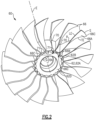
- Figure 2 illustrates a rotor assembly 60 for a gas turbine engine according to an example.
- the rotor assembly 60 can be incorporated into the fan section 22 of Figure 1 , for example.
- other portions of the gas turbine engine 20, such as fan case 15, other portions of the engine static structure 36, and airfoils including static vanes in the compressor section 24, and other systems may benefit from the teachings disclosed herein, such as a multi-stage fan or a land-based turbine.
- the rotor assembly 60 includes a rotatable hub 62 mechanically attached or otherwise mounted to a fan shaft 64.
- the rotatable hub 62 includes a main body 62A that extends along the longitudinal axis E.
- the longitudinal axis E can be parallel to or collinear with the engine longitudinal axis A of Figure 1 .
- the fan shaft 64 and hub 62 are rotatable about the longitudinal axis E.
- the fan shaft 64 can be rotatably coupled to the low pressure turbine 46, as illustrated in Figure 1 , for example.
- the rotor assembly 60 includes an array of airfoils 66 circumferentially distributed about and carried by an outer periphery 62B of the rotatable hub 62.
- Each airfoil 66 includes an airfoil section 66A extending from a root section 66B.
- the hub 62 includes a plurality of retention slots 62C that extend inwardly from the outer periphery 62B of the hub 62.
- Each root section 66B is slideably received in a respective one of the retention slots 62C to mechanically attach or otherwise secure the airfoil 66 to the hub 62.
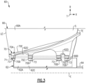
- the root section 66B can have a dovetail geometry that mates with a contour of the respective retention slot 62C (also shown in dashed lines in Figure 3 for illustrative purposes).
- the rotor assembly 60 includes an array of platforms 70.
- the platforms 70 are separate and distinct from the airfoils 66. In other examples, the platforms 70 are integrally formed with one or more of the airfoils 66.
- the platforms 70 are circumferentially distributed about the outer periphery 62B of the hub 62.
- the platforms 70 are situated between and abut against adjacent pairs of airfoils 66 to define an inner boundary of a gas path along the rotor assembly 60, as illustrated in Figure 2 .
- the platforms 70 are dimensioned to support the adjacent airfoils 66 and limit or otherwise oppose circumferential movement of the airfoils 66 during engine operation.
- the rotor assembly 60 includes a plurality of retention pins 71. Each platform 70 can be mechanically attached or otherwise secured to the hub 62 with a respective one of the retention pins 71.
- the airfoil section 66A extends between a leading edge LE and a trailing edge TE in a chordwise direction X, and extends in a radial direction R between the root section 66B and a tip portion 66C ( Figure 2 ) to provide an aerodynamic surface.
- the tip portion 66C defines a terminal end or radially outermost extent of the airfoil 66 to establish a clearance gap with fan case 15 ( Figure 1 ).
- the airfoil section 66A defines a pressure side P ( Figure 2 ) and a suction side S separated in a thickness direction T.
- Each platform 70 includes a platform body 70A including a plurality of axially spaced apart flanges 70B.
- the platform body 70A includes a platform base 70E dimensioned to abut against and extend along the airfoil section 66A of adjacent airfoils 66.
- the platform base 70E defines an aerodynamic contour and gas path surface between the adjacent airfoils 66.
- the platform body 70A defines one or more slots 70C between the flanges 70B.
- Each slot 70C is dimensioned to receive a respective flange 62D of the hub 62.
- Each flange 62D can have an annular geometry that extends circumferentially about the longitudinal axis E, as illustrated by Figure 2 .
- Each platform 70 is dimensioned to receive at least one retention pin 71 (shown in dashed lines in Figure 3 ) to mechanically attach and mount the platform 70 to the hub 62.
- Each of the flanges 70B can include a respective platform bushing 73.
- the bushings 73 can be axially aligned and dimensioned to slideably receive a common one of the retention pins 71, as illustrated by Figure 3 .
- Each retention pin 71 is dimensioned to extend through the flanges 62D of the hub 62 and through the flanges 70B of the respective platform 70 to mechanically attach the platform 70 to the hub 62.
- the rotor assembly 60 can include one or more composite components, such as the airfoils 66 and/or platforms 70.
- Example composite materials include thermoplastics and ceramics such as ceramic matrix composites (CMC) having one or more ply layers or fibers in a resin matrix.
- CMC ceramic matrix composites
- the rotor assembly 60 can include one or more internal cavities defined in the composite components.
- the composite components may be constructed from a layup of plies, for example. Contouring of the component may cause the plies to define the internal cavities.
- the internal cavities can be at least partially filled or occupied with material utilizing the techniques disclosed herein to improve fabrication and structural support of the component.
- the platform 70 is a composite structure including a plurality of composite layers L shaped to a predetermined geometry.
- the composite layers L define the platform body 70A and flanges 70B.
- Example materials include one or more plies of uni-tape, braided yarns, fabric, and two-dimensional or three-dimensional woven fibers, for example.
- uni-tape plies include a plurality of fibers oriented in the same direction ("uni-directional), and fabric includes woven or interlaced fibers, each known in the art.
- Example fiber constructions include carbon fibers, fiberglass, Kevlar ® , a ceramic such as Nextel TM , a polyethylene such as Spectra ® , and/or a combination of fibers.
- the composite layers L include first and second sets of ply layers L-1, L-2 that define an outer periphery 70P of the platform 70.
- the first set of ply layers L-1 define the platform base 70E.
- the second set of ply layers L-2 extend from the first set of ply layers L-1 to define the flanges 70B.
- the composite layers L are arranged such that the flanges 70B form respective arches that extend outwardly from the platform base 70E to define respective hollow cavities 70F.
- the composite layers L include a third set of ply layers L-3 that abut against the first and second sets of ply layers L-1, L-2 to surround the hollow cavities 70F.
- the hollow cavities 70F can be arranged to define portions of an elongated passage 70G.
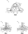
- the passage 70G is at least partially surrounded by the third set of ply layers L-3 and extends longitudinally between opposed end portions 70H of the platform body 70A and through each of the flanges 70B, as illustrated by Figures 4 and 6 .
- Each composite layer L can include one or more sublayers LL, as illustrated by Figures 7 and 8 .
- the composite layers L can be dimensioned and formed to follow a contour of the platform 70. At least some of the composite layers L are joined together to define one or more of the internal cavities 70D. At least some of the internal cavities 70D are bounded by the platform base 70E and are defined in the flanges 70B. Each cavity 70D is at least partially enclosed by adjacent composite layers L and can be provided with one or more openings to an exterior of the platform 70.
- Each platform 70 can include one or more support members or fillers 74 received in a respective cavity 70D.
- the fillers 74 are dimensioned to complement a geometry of a respective one of the inner cavities 70D and serve to at least partially support the adjacent composite layers L during fabrication.
- the fillers 74 can also serve as structural members to support the composite layers L during engine operation.
- the platform 70 includes first and second fillers 74-1, 74-2 that extend along the platform base 70E.
- the platform 70 includes a plurality of fillers 74 that define portions of the flanges 70B, such as filler 74-3.
- Filler 74-2 is dimensioned to extend along and outwardly from the platform base 70E to define at least one of the flanges 70B.
- Figure 5 illustrates a perspective view of the fillers 74-1, 74-2, 74-3 for illustrative purposes. It should be appreciated that the specific geometry of each filler 74 can be dimensioned according to a geometry of the platform 70.
- adjacent layers L can be arranged to define one or more contours of the platform 70.
- the layers L can curve inwardly and/or outwardly from adjacent layers L.
- the geometry of the layers L can cause a cross section or perimeter of the respective internal cavity 70D to taper, as illustrated by the internal cavities 70D associated with filler 74-1 at junctions 11, J2 and J3.
- Some of the layers L may arranged to have a relatively large turning radii along the respective contour such that the internal cavities 70D associated with fillers 74-1, 74-2 have a generally deltoid or delta-shaped geometry formed by inner radii, for example.
- the fillers 74 can be dimensioned to occupy the relatively sharp corners of the internal cavities 70D defined by the inner radii, which may otherwise be difficult to avoid during fabrication due to dimensional aspects and construction of the layers including maximum turning radii, for example.
- the fillers 74 can be utilized to maintain a geometry of the platform 70 during layup of the layers L, which can improve the structural capability and manufacturability of the layers L.
- each filler 74 includes a lattice structure 76 situated in a respective one of the internal cavities 70D, as illustrated by fillers 74-1, 74-2, 74-3 and respective lattice structures 76-1, 76-2, and 76-3.
- the fillers 74 are constructed from uni-tape plies, discontinuous chopped fibers in a resin matrix, preforms made of a bulk or sheet molding compound, and thermoplastics.
- the lattice structure 76 is dimensioned to extend between surfaces of the composite layers L that bound the respective internal cavity 70D.
- the lattice structure 76 can serve as a scaffold to provide structural support and rigidity to the adjacent layers L and distribute structural loads across portions of the platform 70.
- the lattice structures 76 can be constructed to have relatively high stiffness, high strength and low weight.
- Each lattice structure 76 can include a skin 76A that is dimensioned to follow a surface contour bounding the respective internal cavity 70D.
- the lattice structure 76 includes a plurality of branches 76B that extend from and/or between a plurality of nodes 76C. At least some of the branches 76B and/or nodes 76C can be spaced apart from surfaces of the skin 76A.
- the skin 76A is dimensioned to at least partially enclose the branches and nodes 76B, 76C.
- a respective bushing 73 is situated in the internal cavity 70D.
- Lattice structure 76-3 extends between the bushing 73 and surfaces of the composite layers L that bound the internal cavity 70D.
- the lattice structure 76 serves to provide a structural load path between the bushing 73 and composite layers L.
- the lattice structure 76 can be metallic.
- Example metallic materials include metals or alloys such as titanium and steel.
- the lattice structure 76 is non-metallic and is constructed from a composite material such as a thermoplastic.
- a volume of the respective internal cavity 70D between surfaces of the layers L and surfaces of the lattice structure including the skin 76A, branches 76B, and nodes 76C can be hollow, as illustrated in Figure 6 .
- the skin 76A is dimensioned to completely enclose the branches and nodes 76B, 76C to reduce a likelihood of migration of resin material into an interior of the lattice structure 76 during fabrication.
- the hollow architecture and lack of resin in the interior of the lattice structure 76 can reduce a weight of the respective fillers 74 and overall weight of the platform 70 and rotor assembly 60.
- the volume is at least partially occupied by material such as a foam or resin.
- the lattice structure 76 can be fabricated utilizing additive manufacturing techniques such as three-dimensional printing, for example.
- the layers L can be bonded or otherwise secured to the lattice structure 76.
- the lattice structures 76 have a predefined geometry, which reduces variation between actual and predefined geometry of the layers L forming the contours of the platform 70.
- a density of each lattice structure 76 can be constructed with respect to structural loads and other characteristics of the platform 70.
- lattice structure 76-1 of Figure 7 can have a relatively fine or dense distribution of branches 76B and nodes 76C.
- the lattice structure 76-2 has a relatively coarse or less dense distribution of branches 76B and nodes 76C.
- lattice structure 76-1 occupies between 30-50% of a total volume of the respective internal cavity 70D
- lattice structure 76-2 occupies between 10-30% of a total volume of the respective internal cavity 70D.
- Lattice structure 76-1 can be situated adjacent to the pressure side P of the respective airfoil 66 to provide relatively greater stiffness
- lattice structure 76-2 can be situated adjacent to the suction side S of the airfoil 66 to provide relatively greater damping to absorb energy from impacts by foreign object debris (FOD) such as a bird strike.
- the damping can improve the ability of the respective airfoil 66 to sway or move in the circumferential direction, which can improve durability of the components.
- the branches 76B of the lattice structure 76 can be distributed along the perimeter of the respective skin 76A with respect to expected localized stress concentrations or loads on the platform 70.
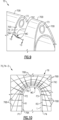
- filler 74-3 defines a wall curvature WC or rim along a perimeter of the skin 76A.
- wall curvature WC is illustrated as being concave, the teachings herein can be utilized for convex and other geometries.
- a cross section of the wall curvature WC and filler 74-3 is shown.
- a first set of the branches 76B extend from a first region R1 between points P1, P2 along the skin 76A.
- a second set of the branches 76B extend from a second region R2 between points P2, P3 along the wall curvature WC.
- a third set of the branches 76B extend from the perimeter of the skin 76A between points P3, P4 along a third region R3.
- An average spacing between adjacent branches 76B along the second region R2 can be less than the first and/or third regions R1, R3 such that the branches 76B are more densely distributed along the second region R2.
- the branches 76B along the second region R2 can fan outwardly from the perimeter of the skin 76A, as illustrated by Figure 10 .
- the fanning arrangement causes the density of the branches 76B in the second region R2 to progressively decrease from an apex of the wall curvature WC toward the first and/or third regions R1, R3.
- the distribution of branches 76B of the lattice structure 76 can be utilized to provide additional structural support and stiffness along the second region R2 which may experience relatively greater stress concentrations due to loading on the first and third regions R1, R3 during engine operation.
- FIGS 11 and 12 illustrate a composite airfoil 166 according to an example.
- the airfoil 166 can be incorporated into the rotor assembly disclosed herein.
- the airfoil 166 includes an airfoil section 166A extending from a root section 166B.
- the airfoil section 166A can include a sheath 167.
- the sheath 167 includes first and second skins 167A, 167B that are joined together to define pressure and suction sides P, S of the airfoil section 166A.
- Various materials can be utilized for the sheath 167.
- the skins 167A, 167B comprise a metallic material such as titanium, stainless steel, nickel, aluminum, or another metal or metal alloy.
- the skins 167A, 167B cooperate to define at least one recess 167C dimensioned to receive a composite core 169.
- the composite core 169 can be constructed from any of the materials and utilizing any of the techniques disclosed herein, such as carbon or carbon fibers.
- the composite core 169 includes one or more composite layers L that form a ceramic matrix composite (CMC).
- the composite layers L extend into and define portions of the airfoil and root sections 166A, 166B.
- the airfoil 166 defines at least one internal cavity 169A in the root section 166B.
- the internal cavity 169A is bounded by surfaces of one or more of the composite layers L and is dimensioned to receive a support member or filler 174. At least one of the composite layers L is dimensioned to loop around the filler 174.
- a perimeter of the internal cavity 169A tapers from the root section 166B towards the tip portion 166C.
- the filler 174 can include a lattice structure 176, including any of the lattice structures disclosed herein.
- the lattice structure 176 includes a skin 176A, a plurality of branches 176B and a plurality of nodes 176C.
- the lattice structure 176 extends between surfaces of the composite layer(s) L that bound the internal cavity 169A.
- FIG. 13 illustrates an airfoil 266 according to another example.
- the airfoil 266 can be incorporated into a portion of the engine 20 and the rotor assembly 60, for example.
- the airfoil 266 is made of a ceramic matrix composite (CMC) including a plurality of composite layers L that define an outer skin or external surfaces of an airfoil section 266A. At least some of the composite layers L bound an internal cavity 269A.
- a support member or filler 274 is situated in the cavity 269A and serves as an airfoil core.
- the filler 274 includes a lattice structure 276 including a skin, branches and nodes 276A, 276B, 276C.
- FIGS 14-16 illustrate example lattice structures that can be incorporated into any of the lattice structures disclosed herein.
- Lattice structure 376 of Figure 14 illustrates a uniform benchmark distribution including a skin, branches and nodes 376A, 376B, 376C.
- Lattice structure 476 of Figure 15 illustrates a diameter graded lattice structure 476 including a skin, branches and nodes 476A, 476B, 476C.
- Figure 16 illustrates a spatially grated lattice structure 576 including a skin, branches and nodes 576A, 576B, 576C.
- uniform benchmark, diameter graded, and spatially graded lattice structures are generally known, incorporation of the lattice structures 376, 476, 576 into a gas turbine engine component utilizing the techniques disclosed herein is not known.
Landscapes
- Engineering & Computer Science (AREA)
- Mechanical Engineering (AREA)
- General Engineering & Computer Science (AREA)
- Chemical & Material Sciences (AREA)
- Materials Engineering (AREA)
- Physics & Mathematics (AREA)
- Fluid Mechanics (AREA)
- Architecture (AREA)
- Composite Materials (AREA)
- Manufacturing & Machinery (AREA)
- Structures Of Non-Positive Displacement Pumps (AREA)
- Turbine Rotor Nozzle Sealing (AREA)
Applications Claiming Priority (3)
| Application Number | Priority Date | Filing Date | Title |
|---|---|---|---|
| US16/216,012 US10774653B2 (en) | 2018-12-11 | 2018-12-11 | Composite gas turbine engine component with lattice structure |
| EP19215168.6A EP3677749B1 (fr) | 2018-12-11 | 2019-12-11 | Plateforme en composite doté d'une structure en treillis |
| EP21207525.3A EP3971390B1 (fr) | 2018-12-11 | 2019-12-11 | Plateforme en composite doté d'une structure en treillis |
Related Parent Applications (2)
| Application Number | Title | Priority Date | Filing Date |
|---|---|---|---|
| EP21207525.3A Division EP3971390B1 (fr) | 2018-12-11 | 2019-12-11 | Plateforme en composite doté d'une structure en treillis |
| EP19215168.6A Division EP3677749B1 (fr) | 2018-12-11 | 2019-12-11 | Plateforme en composite doté d'une structure en treillis |
Publications (2)
| Publication Number | Publication Date |
|---|---|
| EP4357621A2 true EP4357621A2 (fr) | 2024-04-24 |
| EP4357621A3 EP4357621A3 (fr) | 2024-06-19 |
Family
ID=68886777
Family Applications (3)
| Application Number | Title | Priority Date | Filing Date |
|---|---|---|---|
| EP19215168.6A Active EP3677749B1 (fr) | 2018-12-11 | 2019-12-11 | Plateforme en composite doté d'une structure en treillis |
| EP24163069.8A Pending EP4357621A3 (fr) | 2018-12-11 | 2019-12-11 | Composant de moteur à turbine à gaz composite à structure en treillis |
| EP21207525.3A Active EP3971390B1 (fr) | 2018-12-11 | 2019-12-11 | Plateforme en composite doté d'une structure en treillis |
Family Applications Before (1)
| Application Number | Title | Priority Date | Filing Date |
|---|---|---|---|
| EP19215168.6A Active EP3677749B1 (fr) | 2018-12-11 | 2019-12-11 | Plateforme en composite doté d'une structure en treillis |
Family Applications After (1)
| Application Number | Title | Priority Date | Filing Date |
|---|---|---|---|
| EP21207525.3A Active EP3971390B1 (fr) | 2018-12-11 | 2019-12-11 | Plateforme en composite doté d'une structure en treillis |
Country Status (2)
| Country | Link |
|---|---|
| US (2) | US10774653B2 (fr) |
| EP (3) | EP3677749B1 (fr) |
Families Citing this family (21)
| Publication number | Priority date | Publication date | Assignee | Title |
|---|---|---|---|---|
| US10724445B2 (en) * | 2018-01-03 | 2020-07-28 | Raytheon Technologies Corporation | Method of assembly for fan drive gear system with rotating carrier |
| US11738889B2 (en) * | 2019-03-20 | 2023-08-29 | California Institute Of Technology | Integrated satellite chassis with internal propellant tank structure |
| EP3957471A1 (fr) * | 2020-08-19 | 2022-02-23 | Airbus Operations, S.L.U. | Élément de remplissage fabriqué par fabrication additive |
| US11725519B2 (en) | 2021-03-01 | 2023-08-15 | Raytheon Technologies Corporation | Platform for an airfoil of a gas turbine engine |
| US11860345B2 (en) | 2021-04-23 | 2024-01-02 | Bae Systems Information And Electronic Systems Integration Inc. | Midwave infrared discrete zoom lens |
| US20230078480A1 (en) * | 2021-09-10 | 2023-03-16 | Hamilton Sundstrand Corporation | Turbomachinery housing with variable lattice densities |
| US11773746B2 (en) | 2021-09-10 | 2023-10-03 | Hamilton Sundstrand Corporation | Turbomachinery rotor shroud with variable lattice densities |
| US11994141B2 (en) | 2021-09-10 | 2024-05-28 | Hamilton Sundstrand Corporation | Turbomachinery shaft with variable lattice densities |
| US11802488B2 (en) | 2021-09-10 | 2023-10-31 | Hamilton Sundstrand Corporation | Turbomachinery seal plate with variable lattice densities |
| US11988103B2 (en) | 2021-10-27 | 2024-05-21 | General Electric Company | Airfoils for a fan section of a turbine engine |
| US11655828B2 (en) | 2021-10-27 | 2023-05-23 | General Electric Company | Anti-icing systems and airfoils for a fan section of a turbine engine |
| US11560800B1 (en) * | 2021-11-12 | 2023-01-24 | Raytheon Technologies Corporation | Airfoil with fiber plies having interdigitated fingers in trailing end |
| FR3129684B1 (fr) * | 2021-11-30 | 2024-08-30 | Safran Aircraft Engines | Plateforme de roue aubagée pour turbomachine |
| US11668316B1 (en) * | 2022-01-07 | 2023-06-06 | Hamilton Sundstrand Corporation | Rotor formed of multiple metals |
| US12392247B2 (en) * | 2023-06-02 | 2025-08-19 | Rtx Corporation | Airfoil with sandwich composite flange |
| US12006842B1 (en) * | 2023-06-02 | 2024-06-11 | Rtx Corporation | Airfoil with sandwich composite |
| US12571314B2 (en) | 2023-07-07 | 2026-03-10 | General Electric Company | Composite airfoil assembly for a turbine engine |
| US12203390B1 (en) * | 2023-07-07 | 2025-01-21 | General Electric Company | Composite airfoil assembly for a turbine engine |
| US12055065B1 (en) * | 2023-08-24 | 2024-08-06 | General Electric Company | Airfoil for a gas turbine engine having an inner core structure formed of meta-structures and isogrids |
| US12535008B2 (en) | 2023-10-03 | 2026-01-27 | General Electric Company | Airfoil assembly having a composite core |
| US20260063045A1 (en) * | 2024-08-29 | 2026-03-05 | Rtx Corporation | Reinforced Fan Inter-Blade Platforms |
Family Cites Families (193)
| Publication number | Priority date | Publication date | Assignee | Title |
|---|---|---|---|---|
| US2343918A (en) | 1943-05-11 | 1944-03-14 | Howard M Mccoy | Means for deicing propeller spinners |
| US3584972A (en) | 1966-02-09 | 1971-06-15 | Gen Motors Corp | Laminated porous metal |
| US3694104A (en) | 1970-10-07 | 1972-09-26 | Garrett Corp | Turbomachinery blade |
| US3869778A (en) | 1971-12-27 | 1975-03-11 | Raymond W Yancey | Article of manufacture with twisted web |
| US3864199A (en) | 1973-07-26 | 1975-02-04 | Gen Motors Corp | Angular discharge porous sheet |
| US3900629A (en) | 1973-09-14 | 1975-08-19 | Bendix Corp | Porous laminate and method of manufacture |
| US4168348A (en) | 1974-12-13 | 1979-09-18 | Rolls-Royce Limited | Perforated laminated material |
| US4004056A (en) | 1975-07-24 | 1977-01-18 | General Motors Corporation | Porous laminated sheet |
| NL7606801A (nl) | 1975-10-01 | 1977-04-05 | Gen Electric | Soepele gevlochten metaalhuid en werkwijze ter vervaardiging ervan. |
| US4359181A (en) | 1978-05-25 | 1982-11-16 | John Chisholm | Process for making a high heat transfer surface composed of perforated or expanded metal |
| GB2033071B (en) | 1978-10-28 | 1982-07-21 | Rolls Royce | Sheet metal laminate |
| US4302940A (en) | 1979-06-13 | 1981-12-01 | General Motors Corporation | Patterned porous laminated material |
| US4269032A (en) | 1979-06-13 | 1981-05-26 | General Motors Corporation | Waffle pattern porous material |
| FR2483513A1 (fr) | 1980-05-28 | 1981-12-04 | Snecma | Procede pour la fabrication d'aubes de turbine refroidies au moyen d'un corps poreux et produit obtenu suivant ce procede |
| US4407632A (en) | 1981-06-26 | 1983-10-04 | United Technologies Corporation | Airfoil pedestaled trailing edge region cooling configuration |
| GB2168111B (en) | 1984-12-08 | 1988-05-18 | Rolls Royce | Rotor aerofoil blade containment |
| US4642993A (en) | 1985-04-29 | 1987-02-17 | Avco Corporation | Combustor liner wall |
| US4751962A (en) | 1986-02-10 | 1988-06-21 | General Motors Corporation | Temperature responsive laminated porous metal panel |
| US4815939A (en) | 1986-11-03 | 1989-03-28 | Airfoil Textron Inc. | Twisted hollow airfoil with non-twisted internal support ribs |
| US5102300A (en) | 1988-10-07 | 1992-04-07 | United Technologies Corporation | Pinned airfoil propeller assembly |
| US5038014A (en) | 1989-02-08 | 1991-08-06 | General Electric Company | Fabrication of components by layered deposition |
| GB8910241D0 (en) | 1989-05-04 | 1989-06-21 | Secretary Trade Ind Brit | Heat exchangers |
| EP0475658A1 (fr) | 1990-09-06 | 1992-03-18 | General Electric Company | Aube de turbine avec refroidissement en série par jet a travers des nervures internes |
| US5129787A (en) | 1991-02-13 | 1992-07-14 | United Technologies Corporation | Lightweight propulsor blade with internal spars and rigid base members |
| US5165860A (en) | 1991-05-20 | 1992-11-24 | United Technologies Corporation | Damped airfoil blade |
| US5370499A (en) | 1992-02-03 | 1994-12-06 | General Electric Company | Film cooling of turbine airfoil wall using mesh cooling hole arrangement |
| US5660523A (en) | 1992-02-03 | 1997-08-26 | General Electric Company | Turbine blade squealer tip peripheral end wall with cooling passage arrangement |
| US5295530A (en) | 1992-02-18 | 1994-03-22 | General Motors Corporation | Single-cast, high-temperature, thin wall structures and methods of making the same |
| US5240377A (en) | 1992-02-25 | 1993-08-31 | Williams International Corporation | Composite fan blade |
| EP0564027A1 (fr) | 1992-03-31 | 1993-10-06 | Akzo Nobel N.V. | Echangeur de chaleur, procédé de sa fabrication et des applications |
| US5370449A (en) | 1993-10-12 | 1994-12-06 | Eaton Corporation | Electrically operated parking brake system |
| DE4338457C2 (de) | 1993-11-11 | 1998-09-03 | Mtu Muenchen Gmbh | Bauteil aus Metall oder Keramik mit dichter Außenschale und porösem Kern und Herstellungsverfahren |
| US5562419A (en) | 1995-06-06 | 1996-10-08 | General Electric Company | Shrouded fan blisk |
| US5607778A (en) | 1995-07-20 | 1997-03-04 | Purolator Products Company | Method of manufacturing a porous metal mat |
| US5558497A (en) | 1995-07-31 | 1996-09-24 | United Technologies Corporation | Airfoil vibration damping device |
| US5837960A (en) | 1995-08-14 | 1998-11-17 | The Regents Of The University Of California | Laser production of articles from powders |
| JPH1054204A (ja) | 1996-05-20 | 1998-02-24 | General Electric Co <Ge> | ガスタービン用の多構成部翼 |
| US5752801A (en) | 1997-02-20 | 1998-05-19 | Westinghouse Electric Corporation | Apparatus for cooling a gas turbine airfoil and method of making same |
| US5839882A (en) | 1997-04-25 | 1998-11-24 | General Electric Company | Gas turbine blade having areas of different densities |
| US5931638A (en) | 1997-08-07 | 1999-08-03 | United Technologies Corporation | Turbomachinery airfoil with optimized heat transfer |
| US5975841A (en) | 1997-10-03 | 1999-11-02 | Thermal Corp. | Heat pipe cooling for turbine stators |
| US6039542A (en) | 1997-12-24 | 2000-03-21 | General Electric Company | Panel damped hybrid blade |
| US5960863A (en) | 1998-01-07 | 1999-10-05 | Hua; Hsu Mei | Dissipating device for computer chips |
| US6167952B1 (en) | 1998-03-03 | 2001-01-02 | Hamilton Sundstrand Corporation | Cooling apparatus and method of assembling same |
| US6231941B1 (en) | 1998-07-14 | 2001-05-15 | The Boeing Company | Radius fillers for a resin transfer molding process |
| US6193465B1 (en) | 1998-09-28 | 2001-02-27 | General Electric Company | Trapped insert turbine airfoil |
| US6126396A (en) | 1998-12-09 | 2000-10-03 | General Electric Company | AFT flowing serpentine airfoil cooling circuit with side wall impingement cooling chambers |
| US6235370B1 (en) | 1999-03-03 | 2001-05-22 | Siemens Westinghouse Power Corporation | High temperature erosion resistant, abradable thermal barrier composite coating |
| GB9906450D0 (en) | 1999-03-19 | 1999-05-12 | Rolls Royce Plc | Aerofoil blade damper |
| US6213720B1 (en) | 1999-06-11 | 2001-04-10 | Alliedsignal, Inc. | High strength composite reinforced turbomachinery disk |
| US6391251B1 (en) | 1999-07-07 | 2002-05-21 | Optomec Design Company | Forming structures from CAD solid models |
| US6454536B1 (en) | 2000-02-09 | 2002-09-24 | General Electric Company | Adhesion enhancers to promote bonds of improved strength between elastomers metals in lightweight aircraft fan blades |
| JP3632003B2 (ja) | 2000-03-07 | 2005-03-23 | 三菱重工業株式会社 | ガスタービン分割環 |
| DE10024302A1 (de) | 2000-05-17 | 2001-11-22 | Alstom Power Nv | Verfahren zur Herstellung eines thermisch belasteten Gussteils |
| US6397922B1 (en) | 2000-05-24 | 2002-06-04 | Massachusetts Institute Of Technology | Molds for casting with customized internal structure to collapse upon cooling and to facilitate control of heat transfer |
| US6617003B1 (en) | 2000-11-06 | 2003-09-09 | General Electric Company | Directly cooled thermal barrier coating system |
| US6511762B1 (en) | 2000-11-06 | 2003-01-28 | General Electric Company | Multi-layer thermal barrier coating with transpiration cooling |
| GB0100695D0 (en) | 2001-01-11 | 2001-02-21 | Rolls Royce Plc | a turbomachine blade |
| US7785098B1 (en) | 2001-06-05 | 2010-08-31 | Mikro Systems, Inc. | Systems for large area micro mechanical systems |
| US7141812B2 (en) | 2002-06-05 | 2006-11-28 | Mikro Systems, Inc. | Devices, methods, and systems involving castings |
| US7063131B2 (en) | 2001-07-12 | 2006-06-20 | Nuvera Fuel Cells, Inc. | Perforated fin heat exchangers and catalytic support |
| GB0117110D0 (en) | 2001-07-13 | 2001-09-05 | Siemens Ag | Coolable segment for a turbomachinery and combustion turbine |
| US6761956B2 (en) | 2001-12-20 | 2004-07-13 | General Electric Company | Ventilated thermal barrier coating |
| EP1327703A1 (fr) | 2002-01-15 | 2003-07-16 | Siemens Aktiengesellschaft | Système de revêtement avec une couche poreuse |
| DE10261071A1 (de) | 2002-12-24 | 2004-07-08 | Rolls-Royce Deutschland Ltd & Co Kg | Brennkammerwandelement für eine Gasturbine |
| US7029232B2 (en) | 2003-02-27 | 2006-04-18 | Rolls-Royce Plc | Abradable seals |
| US7048986B2 (en) | 2003-06-12 | 2006-05-23 | Northrop Grumman Corporation | End gaps of filled honeycomb |
| EP1496140A1 (fr) | 2003-07-09 | 2005-01-12 | Siemens Aktiengesellschaft | Structure stratifiée et procédé pour sa production |
| GB2403987B (en) | 2003-07-11 | 2006-09-06 | Rolls Royce Plc | Blades |
| US7128532B2 (en) | 2003-07-22 | 2006-10-31 | The Boeing Company | Transpiration cooling system |
| US6955523B2 (en) | 2003-08-08 | 2005-10-18 | Siemens Westinghouse Power Corporation | Cooling system for a turbine vane |
| GB2405186B (en) | 2003-08-20 | 2005-10-26 | Rolls Royce Plc | A component with internal damping |
| DE10341515A1 (de) | 2003-09-04 | 2005-03-31 | Rolls-Royce Deutschland Ltd & Co Kg | Anordnung zur Kühlung hoch wärmebelasteter Bauteile |
| EP1528343A1 (fr) | 2003-10-27 | 2005-05-04 | Siemens Aktiengesellschaft | Tuile réfractaire avec des éléments de renforcement noyés pour révêtement d'une chambre de combustion de turbines à gaz |
| EP1533113A1 (fr) | 2003-11-14 | 2005-05-25 | Siemens Aktiengesellschaft | Système stratifié pour dissipation de chaleur à haute température et méthode de fabrication |
| US7153464B2 (en) | 2003-12-01 | 2006-12-26 | General Electric Company | Method of making porous ceramic matrix composites |
| DE10360164A1 (de) | 2003-12-20 | 2005-07-21 | Mtu Aero Engines Gmbh | Gasturbinenbauteil |
| US7125225B2 (en) | 2004-02-04 | 2006-10-24 | United Technologies Corporation | Cooled rotor blade with vibration damping device |
| US7121801B2 (en) | 2004-02-13 | 2006-10-17 | United Technologies Corporation | Cooled rotor blade with vibration damping device |
| US7217093B2 (en) | 2004-05-27 | 2007-05-15 | United Technologies Corporation | Rotor blade with a stick damper |
| US7328580B2 (en) | 2004-06-23 | 2008-02-12 | General Electric Company | Chevron film cooled wall |
| US20060021308A1 (en) | 2004-07-29 | 2006-02-02 | Merkel Gregory A | Mullite-aluminum titanate body and method for making same |
| US7144220B2 (en) | 2004-07-30 | 2006-12-05 | United Technologies Corporation | Investment casting |
| GB0418906D0 (en) | 2004-08-25 | 2004-09-29 | Rolls Royce Plc | Internally cooled aerofoils |
| US7121800B2 (en) | 2004-09-13 | 2006-10-17 | United Technologies Corporation | Turbine blade nested seal damper assembly |
| GB2451779A (en) | 2004-09-22 | 2009-02-11 | Rolls Royce Plc | Manufacturing aerofoil with metal foam core |
| GB0424593D0 (en) | 2004-11-06 | 2004-12-08 | Rolls Royce Plc | A component having a film cooling arrangement |
| US7478994B2 (en) | 2004-11-23 | 2009-01-20 | United Technologies Corporation | Airfoil with supplemental cooling channel adjacent leading edge |
| US7435058B2 (en) | 2005-01-18 | 2008-10-14 | Siemens Power Generation, Inc. | Ceramic matrix composite vane with chordwise stiffener |
| WO2006086342A2 (fr) | 2005-02-07 | 2006-08-17 | Aerocomposites, Inc. | Pale de rotor a pas variable presentant des doubles elements de retenue souples |
| US7377746B2 (en) | 2005-02-21 | 2008-05-27 | General Electric Company | Airfoil cooling circuits and method |
| US7422417B2 (en) | 2005-05-05 | 2008-09-09 | Florida Turbine Technologies, Inc. | Airfoil with a porous fiber metal layer |
| US7500828B2 (en) | 2005-05-05 | 2009-03-10 | Florida Turbine Technologies, Inc. | Airfoil having porous metal filled cavities |
| US7255536B2 (en) | 2005-05-23 | 2007-08-14 | United Technologies Corporation | Turbine airfoil platform cooling circuit |
| US7745022B2 (en) | 2005-07-22 | 2010-06-29 | Siemens Energy, Inc. | CMC with multiple matrix phases separated by diffusion barrier |
| GB2428749B (en) | 2005-08-02 | 2007-11-28 | Rolls Royce Plc | A component comprising a multiplicity of cooling passages |
| US7658590B1 (en) | 2005-09-30 | 2010-02-09 | Florida Turbine Technologies, Inc. | Turbine airfoil with micro-tubes embedded with a TBC |
| US7270517B2 (en) | 2005-10-06 | 2007-09-18 | Siemens Power Generation, Inc. | Turbine blade with vibration damper |
| GB0521826D0 (en) | 2005-10-26 | 2005-12-07 | Rolls Royce Plc | Wall cooling arrangement |
| DE102006004090A1 (de) | 2006-01-28 | 2007-08-02 | Mtu Aero Engines Gmbh | Leitschaufelsegment einer Gasturbine |
| JP5372494B2 (ja) | 2006-03-17 | 2013-12-18 | 日本碍子株式会社 | ハニカム構造体の製造方法 |
| GB0605802D0 (en) | 2006-03-23 | 2006-05-03 | Rolls Royce Plc | A heat exchanger |
| DE102006049216A1 (de) | 2006-10-18 | 2008-04-24 | Mtu Aero Engines Gmbh | Hochdruckturbinen-Rotor und Verfahren zur Herstellung eines Hochdruckturbinen-Rotors |
| US7866372B2 (en) | 2006-12-20 | 2011-01-11 | The Boeing Company | Method of making a heat exchanger core component |
| US7866377B2 (en) | 2006-12-20 | 2011-01-11 | The Boeing Company | Method of using minimal surfaces and minimal skeletons to make heat exchanger components |
| US7810552B2 (en) | 2006-12-20 | 2010-10-12 | The Boeing Company | Method of making a heat exchanger |
| US7597533B1 (en) | 2007-01-26 | 2009-10-06 | Florida Turbine Technologies, Inc. | BOAS with multi-metering diffusion cooling |
| US7717677B1 (en) | 2007-01-31 | 2010-05-18 | Florida Turbine Technologies, Inc. | Multi-metering and diffusion transpiration cooled airfoil |
| US8694895B2 (en) | 2007-02-05 | 2014-04-08 | Microsoft Corporation | Human interaction with application from email client |
| US8257809B2 (en) | 2007-03-08 | 2012-09-04 | Siemens Energy, Inc. | CMC wall structure with integral cooling channels |
| US20080237403A1 (en) | 2007-03-26 | 2008-10-02 | General Electric Company | Metal injection molding process for bimetallic applications and airfoil |
| US7968144B2 (en) | 2007-04-10 | 2011-06-28 | Siemens Energy, Inc. | System for applying a continuous surface layer on porous substructures of turbine airfoils |
| US7828526B2 (en) | 2007-04-11 | 2010-11-09 | General Electric Company | Metallic blade having a composite inlay |
| GB0709838D0 (en) | 2007-05-23 | 2007-07-04 | Rolls Royce Plc | A hollow blade and a method of manufacturing a hollow blade |
| US20100025001A1 (en) | 2007-06-25 | 2010-02-04 | Ching-Pang Lee | Methods for fabricating gas turbine components using an integrated disposable core and shell die |
| US7857588B2 (en) | 2007-07-06 | 2010-12-28 | United Technologies Corporation | Reinforced airfoils |
| US8182228B2 (en) | 2007-08-16 | 2012-05-22 | General Electric Company | Turbine blade having midspan shroud with recessed wear pad and methods for manufacture |
| FR2921099B1 (fr) | 2007-09-13 | 2013-12-06 | Snecma | Dispositif d'amortissement pour aube en materiau composite |
| US8241003B2 (en) | 2008-01-23 | 2012-08-14 | United Technologies Corp. | Systems and methods involving localized stiffening of blades |
| ES2442873T3 (es) | 2008-03-31 | 2014-02-14 | Alstom Technology Ltd | Perfil aerodinámico de turbina de gas |
| GB2459262B (en) | 2008-04-15 | 2010-09-22 | Rolls Royce Plc | Solid freeform fabricated damper |
| JP2011521153A (ja) | 2008-05-13 | 2011-07-21 | ローテイティング コンポジット テクノロジーズ, エルエルシー | ファンブレードの保持および可変ピッチのためのシステム |
| GB0808840D0 (en) | 2008-05-15 | 2008-06-18 | Rolls Royce Plc | A compound structure |
| US8661826B2 (en) | 2008-07-17 | 2014-03-04 | Rolls-Royce Plc | Combustion apparatus |
| US8167573B2 (en) | 2008-09-19 | 2012-05-01 | Siemens Energy, Inc. | Gas turbine airfoil |
| EP2184445A1 (fr) | 2008-11-05 | 2010-05-12 | Siemens Aktiengesellschaft | Support d'aubes statorique axialement segmenté d'une turbine à gaz |
| GB2465337B (en) | 2008-11-12 | 2012-01-11 | Rolls Royce Plc | A cooling arrangement |
| ATE528606T1 (de) | 2008-12-16 | 2011-10-15 | Siemens Ag | Multi-impingement-verbund zum kühlen einer wand |
| FR2943102B1 (fr) | 2009-03-12 | 2014-05-02 | Snecma | Aube en materiau composite comportant un dispositif d'amortissement. |
| US8052378B2 (en) | 2009-03-18 | 2011-11-08 | General Electric Company | Film-cooling augmentation device and turbine airfoil incorporating the same |
| US8585368B2 (en) | 2009-04-16 | 2013-11-19 | United Technologies Corporation | Hybrid structure airfoil |
| US8079821B2 (en) | 2009-05-05 | 2011-12-20 | Siemens Energy, Inc. | Turbine airfoil with dual wall formed from inner and outer layers separated by a compliant structure |
| US8828311B2 (en) | 2009-05-15 | 2014-09-09 | Board Of Regents, The University Of Texas System | Reticulated mesh arrays and dissimilar array monoliths by additive layered manufacturing using electron and laser beam melting |
| WO2011019661A1 (fr) | 2009-08-09 | 2011-02-17 | Rolls-Royce Corporation | Procédé pour former un article coulé |
| US8292583B2 (en) | 2009-08-13 | 2012-10-23 | Siemens Energy, Inc. | Turbine blade having a constant thickness airfoil skin |
| GB0916758D0 (en) | 2009-09-24 | 2009-11-04 | Rolls Royce Plc | A hybrid component |
| DE102009048665A1 (de) | 2009-09-28 | 2011-03-31 | Siemens Aktiengesellschaft | Turbinenschaufel und Verfahren zu deren Herstellung |
| US9618278B2 (en) | 2009-12-02 | 2017-04-11 | Denkenberger Thermal, Llc | Microchannel expanded heat exchanger |
| WO2011075013A1 (fr) | 2009-12-17 | 2011-06-23 | Volvo Aero Corporation | Agencement et procédé pour le refroidissement à circuit fermé d'un composant de moteur de turbine à gaz |
| DE102009060706B4 (de) | 2009-12-29 | 2014-12-04 | Airbus Operations Gmbh | Verfahren sowie Vorrichtung zur Herstellung einer Versteifungsstruktur für ein Flugzeugrumpfsegment sowie eine Versteifungsstruktur |
| US20110194941A1 (en) | 2010-02-05 | 2011-08-11 | United Technologies Corporation | Co-cured sheath for composite blade |
| US20110211965A1 (en) | 2010-02-26 | 2011-09-01 | United Technologies Corporation | Hollow fan blade |
| US8959886B2 (en) | 2010-07-08 | 2015-02-24 | Siemens Energy, Inc. | Mesh cooled conduit for conveying combustion gases |
| US9334741B2 (en) | 2010-04-22 | 2016-05-10 | Siemens Energy, Inc. | Discreetly defined porous wall structure for transpirational cooling |
| US8616801B2 (en) | 2010-04-29 | 2013-12-31 | Siemens Energy, Inc. | Gusset with fibers oriented to strengthen a CMC wall intersection anisotropically |
| US8936068B2 (en) | 2010-06-01 | 2015-01-20 | Siemens Energy, Inc. | Method of casting a component having interior passageways |
| US8647053B2 (en) | 2010-08-09 | 2014-02-11 | Siemens Energy, Inc. | Cooling arrangement for a turbine component |
| US8714926B2 (en) | 2010-09-17 | 2014-05-06 | Siemens Energy, Inc. | Turbine component cooling channel mesh with intersection chambers |
| US9556742B2 (en) | 2010-11-29 | 2017-01-31 | United Technologies Corporation | Composite airfoil and turbine engine |
| US8793871B2 (en) | 2011-03-17 | 2014-08-05 | Siemens Energy, Inc. | Process for making a wall with a porous element for component cooling |
| US8936440B2 (en) | 2011-05-26 | 2015-01-20 | United Technologies Corporation | Hybrid rotor disk assembly with ceramic matrix composites platform for a gas turbine engine |
| DE102011079634A1 (de) | 2011-07-22 | 2013-01-24 | Siemens Aktiengesellschaft | Vorrichtung zum Kühlen und Verfahren zu deren Herstellung sowie Verwendung der Vorrichtung |
| US20130064676A1 (en) | 2011-09-13 | 2013-03-14 | United Technologies Corporation | Composite filled metal airfoil |
| US8944773B2 (en) | 2011-11-01 | 2015-02-03 | United Technologies Corporation | Rotor blade with bonded cover |
| US9221120B2 (en) | 2012-01-04 | 2015-12-29 | United Technologies Corporation | Aluminum fan blade construction with welded cover |
| US10260351B2 (en) | 2012-03-16 | 2019-04-16 | United Technologies Corporation | Fan blade and method of manufacturing same |
| US9470095B2 (en) | 2012-04-24 | 2016-10-18 | United Technologies Corporation | Airfoil having internal lattice network |
| FR2992887B1 (fr) | 2012-07-09 | 2015-05-01 | Snecma | Procede de fixation d'un renfort metallique structurel sur une partie d'une aube de turbine a gaz en materiau composite et moule d'injection pour la mise en oeuvre d'un tel procede |
| US8733156B2 (en) * | 2012-07-16 | 2014-05-27 | United Technologies Corporation | PMC laminate embedded hypotube lattice |
| US9370921B2 (en) | 2012-11-01 | 2016-06-21 | The Boeing Company | Composite radius fillers and methods of forming the same |
| US9506353B2 (en) | 2012-12-19 | 2016-11-29 | United Technologies Corporation | Lightweight shrouded fan blade |
| US10156359B2 (en) | 2012-12-28 | 2018-12-18 | United Technologies Corporation | Gas turbine engine component having vascular engineered lattice structure |
| WO2014163679A1 (fr) * | 2013-03-12 | 2014-10-09 | Uskert Richard C | Surface portante composite en matrice de céramique, appareil et procédé correspondants |
| WO2015009448A1 (fr) | 2013-07-19 | 2015-01-22 | United Technologies Corporation | Noyau réalisé par fabrication additive |
| JP5962942B2 (ja) | 2013-08-19 | 2016-08-03 | 株式会社Ihi | 複合材翼 |
| WO2015026430A1 (fr) | 2013-08-20 | 2015-02-26 | United Technologies Corporation | Plaque de revêtement de plateforme de canalisation |
| WO2015069335A2 (fr) | 2013-09-09 | 2015-05-14 | United Technologies Corporation | Pales de ventilateur et procédés de fabrication |
| WO2015034612A1 (fr) | 2013-09-09 | 2015-03-12 | United Technologies Corporation | Pales de ventilateur et procédés de fabrication |
| WO2015073096A2 (fr) * | 2013-09-13 | 2015-05-21 | United Technologies Corporation | Plateforme de ventilateur |
| EP3047105B1 (fr) | 2013-09-17 | 2021-06-09 | Raytheon Technologies Corporation | Noyau de refroidissement de plate-forme pour aube de rotor de turbine à gaz |
| EP3080417B1 (fr) | 2013-12-13 | 2023-03-15 | Raytheon Technologies Corporation | Montage d'espaceur de plateforme d'aube de soufflante |
| US9669458B2 (en) | 2014-02-06 | 2017-06-06 | General Electric Company | Micro channel and methods of manufacturing a micro channel |
| US10035309B2 (en) | 2014-04-03 | 2018-07-31 | The Boeing Company | Radius fillers for composite structures, composite structures that include radius fillers, and systems and methods of forming the same |
| US10400674B2 (en) | 2014-05-09 | 2019-09-03 | United Technologies Corporation | Cooled fuel injector system for a gas turbine engine and method for operating the same |
| US20160023272A1 (en) | 2014-05-22 | 2016-01-28 | United Technologies Corporation | Turbulating cooling structures |
| US10695958B2 (en) | 2014-06-13 | 2020-06-30 | The Boeing Company | Lattice reinforced radius filler |
| US9587496B2 (en) | 2014-08-07 | 2017-03-07 | General Electric Company | Turbine blade mid-span shroud |
| US10563522B2 (en) * | 2014-09-22 | 2020-02-18 | Rolls-Royce North American Technologies Inc. | Composite airfoil for a gas turbine engine |
| BE1022481B1 (fr) * | 2014-10-28 | 2016-05-02 | Techspace Aero S.A. | Aube a treillis de compresseur de turbomachine axiale |
| US9982544B2 (en) | 2014-11-12 | 2018-05-29 | United Technologies Corporation | Cooling having tailored flow resistance |
| US9920429B2 (en) | 2014-12-01 | 2018-03-20 | Raytheon Company | Method for manufacturing polymer-metal composite structural component |
| GB201507281D0 (en) | 2015-04-29 | 2015-06-10 | Composite Technology & Applic Ltd | Methods and systems for bonding |
| DE102015213087A1 (de) * | 2015-07-13 | 2017-01-19 | Siemens Aktiengesellschaft | Schaufel für eine Strömungskraftmaschine und Verfahren zu deren Herstellung |
| US9976426B2 (en) * | 2015-07-21 | 2018-05-22 | United Technologies Corporation | Fan platform with stiffening feature |
| US9987659B2 (en) * | 2015-10-19 | 2018-06-05 | United Technologies Corporation | Nanotube enhancement of interlaminar performance for a composite component |
| US10634143B2 (en) * | 2015-12-23 | 2020-04-28 | Emerson Climate Technologies, Inc. | Thermal and sound optimized lattice-cored additive manufactured compressor components |
| US10563516B2 (en) | 2016-07-06 | 2020-02-18 | General Electric Company | Turbine engine and method of assembling |
| US10730112B2 (en) | 2016-08-02 | 2020-08-04 | Raytheon Technologies Corporation | Micro lattice hybrid composite fan blade |
| JP2018066289A (ja) | 2016-10-18 | 2018-04-26 | 株式会社Ihi | ファン動翼及びその製造方法 |
| FR3059268B1 (fr) | 2016-11-25 | 2020-02-21 | Safran Aircraft Engines | Procede de fabrication d'un element profile en materiau composite avec fixation d'un renfort metallique par rivetage. |
| US10906248B2 (en) | 2016-12-20 | 2021-02-02 | Textron Innovations, Inc. | Additive manufacturing method for improved core structure |
| US10844724B2 (en) * | 2017-06-26 | 2020-11-24 | General Electric Company | Additively manufactured hollow body component with interior curved supports |
| US11174741B2 (en) * | 2018-04-19 | 2021-11-16 | Raytheon Technologies Corporation | Platform for an airfoil of a gas turbine engine |
-
2018
- 2018-12-11 US US16/216,012 patent/US10774653B2/en active Active
-
2019
- 2019-12-11 EP EP19215168.6A patent/EP3677749B1/fr active Active
- 2019-12-11 EP EP24163069.8A patent/EP4357621A3/fr active Pending
- 2019-12-11 EP EP21207525.3A patent/EP3971390B1/fr active Active
-
2020
- 2020-09-11 US US17/018,188 patent/US11168568B2/en active Active
Also Published As
| Publication number | Publication date |
|---|---|
| EP3971390A1 (fr) | 2022-03-23 |
| US11168568B2 (en) | 2021-11-09 |
| EP3677749B1 (fr) | 2022-01-26 |
| EP3677749A3 (fr) | 2020-09-16 |
| EP3971390B1 (fr) | 2024-03-13 |
| US10774653B2 (en) | 2020-09-15 |
| EP3677749A2 (fr) | 2020-07-08 |
| EP4357621A3 (fr) | 2024-06-19 |
| US20210003016A1 (en) | 2021-01-07 |
| US20200182066A1 (en) | 2020-06-11 |
Similar Documents
| Publication | Publication Date | Title |
|---|---|---|
| EP3677749B1 (fr) | Plateforme en composite doté d'une structure en treillis | |
| EP3693548B1 (fr) | Platforme composite d'une turbine à gaz | |
| US11732597B2 (en) | Double box composite seal assembly with insert for gas turbine engine | |
| US11215054B2 (en) | Airfoil with encapsulating sheath | |
| US12286905B2 (en) | Rotor assembly for gas turbine engines | |
| US11306601B2 (en) | Pinned airfoil for gas turbine engines | |
| US12006842B1 (en) | Airfoil with sandwich composite | |
| EP4219908B1 (fr) | Ensemble joint d'étanchéité composite à double boîte avec agencement de densité de fibres pour moteur à turbine à gaz | |
| US11352897B2 (en) | Double box composite seal assembly for gas turbine engine | |
| US11391167B2 (en) | Hybrid airfoil for gas turbine engines | |
| EP4053382B1 (fr) | Plate-forme inter-aubes en matériau composite |
Legal Events
| Date | Code | Title | Description |
|---|---|---|---|
| PUAI | Public reference made under article 153(3) epc to a published international application that has entered the european phase |
Free format text: ORIGINAL CODE: 0009012 |
|
| STAA | Information on the status of an ep patent application or granted ep patent |
Free format text: STATUS: THE APPLICATION HAS BEEN PUBLISHED |
|
| AC | Divisional application: reference to earlier application |
Ref document number: 3677749 Country of ref document: EP Kind code of ref document: P Ref document number: 3971390 Country of ref document: EP Kind code of ref document: P |
|
| AK | Designated contracting states |
Kind code of ref document: A2 Designated state(s): AL AT BE BG CH CY CZ DE DK EE ES FI FR GB GR HR HU IE IS IT LI LT LU LV MC MK MT NL NO PL PT RO RS SE SI SK SM TR |
|
| REG | Reference to a national code |
Ref country code: DE Ref legal event code: R079 Free format text: PREVIOUS MAIN CLASS: F04D0029320000 Ipc: F01D0005140000 |
|
| PUAL | Search report despatched |
Free format text: ORIGINAL CODE: 0009013 |
|
| AK | Designated contracting states |
Kind code of ref document: A3 Designated state(s): AL AT BE BG CH CY CZ DE DK EE ES FI FR GB GR HR HU IE IS IT LI LT LU LV MC MK MT NL NO PL PT RO RS SE SI SK SM TR |
|
| RIC1 | Information provided on ipc code assigned before grant |
Ipc: F04D 29/32 20060101ALI20240515BHEP Ipc: F01D 11/00 20060101ALI20240515BHEP Ipc: F01D 5/28 20060101ALI20240515BHEP Ipc: F01D 5/14 20060101AFI20240515BHEP |
|
| STAA | Information on the status of an ep patent application or granted ep patent |
Free format text: STATUS: REQUEST FOR EXAMINATION WAS MADE |
|
| 17P | Request for examination filed |
Effective date: 20241219 |