EP4357634A2 - Frein ou embrayage électromagnétique - Google Patents
Frein ou embrayage électromagnétique Download PDFInfo
- Publication number
- EP4357634A2 EP4357634A2 EP24162237.2A EP24162237A EP4357634A2 EP 4357634 A2 EP4357634 A2 EP 4357634A2 EP 24162237 A EP24162237 A EP 24162237A EP 4357634 A2 EP4357634 A2 EP 4357634A2
- Authority
- EP
- European Patent Office
- Prior art keywords
- ring body
- permanent magnet
- armature plate
- outer ring
- electromagnetic brake
- Prior art date
- Legal status (The legal status is an assumption and is not a legal conclusion. Google has not performed a legal analysis and makes no representation as to the accuracy of the status listed.)
- Pending
Links
Images


Classifications
-
- F—MECHANICAL ENGINEERING; LIGHTING; HEATING; WEAPONS; BLASTING
- F16—ENGINEERING ELEMENTS AND UNITS; GENERAL MEASURES FOR PRODUCING AND MAINTAINING EFFECTIVE FUNCTIONING OF MACHINES OR INSTALLATIONS; THERMAL INSULATION IN GENERAL
- F16D—COUPLINGS FOR TRANSMITTING ROTATION; CLUTCHES; BRAKES
- F16D27/00—Magnetically- or electrically- actuated clutches; Control or electric circuits therefor
- F16D27/10—Magnetically- or electrically- actuated clutches; Control or electric circuits therefor with an electromagnet not rotating with a clutching member, i.e. without collecting rings
- F16D27/108—Magnetically- or electrically- actuated clutches; Control or electric circuits therefor with an electromagnet not rotating with a clutching member, i.e. without collecting rings with axially movable clutching members
- F16D27/112—Magnetically- or electrically- actuated clutches; Control or electric circuits therefor with an electromagnet not rotating with a clutching member, i.e. without collecting rings with axially movable clutching members with flat friction surfaces, e.g. discs
-
- F—MECHANICAL ENGINEERING; LIGHTING; HEATING; WEAPONS; BLASTING
- F16—ENGINEERING ELEMENTS AND UNITS; GENERAL MEASURES FOR PRODUCING AND MAINTAINING EFFECTIVE FUNCTIONING OF MACHINES OR INSTALLATIONS; THERMAL INSULATION IN GENERAL
- F16D—COUPLINGS FOR TRANSMITTING ROTATION; CLUTCHES; BRAKES
- F16D27/00—Magnetically- or electrically- actuated clutches; Control or electric circuits therefor
- F16D27/004—Magnetically- or electrically- actuated clutches; Control or electric circuits therefor with permanent magnets combined with electromagnets
-
- F—MECHANICAL ENGINEERING; LIGHTING; HEATING; WEAPONS; BLASTING
- F16—ENGINEERING ELEMENTS AND UNITS; GENERAL MEASURES FOR PRODUCING AND MAINTAINING EFFECTIVE FUNCTIONING OF MACHINES OR INSTALLATIONS; THERMAL INSULATION IN GENERAL
- F16D—COUPLINGS FOR TRANSMITTING ROTATION; CLUTCHES; BRAKES
- F16D27/00—Magnetically- or electrically- actuated clutches; Control or electric circuits therefor
- F16D27/02—Magnetically- or electrically- actuated clutches; Control or electric circuits therefor with electromagnets incorporated in the clutch, i.e. with collecting rings
- F16D27/04—Magnetically- or electrically- actuated clutches; Control or electric circuits therefor with electromagnets incorporated in the clutch, i.e. with collecting rings with axially-movable friction surfaces
- F16D27/06—Magnetically- or electrically- actuated clutches; Control or electric circuits therefor with electromagnets incorporated in the clutch, i.e. with collecting rings with axially-movable friction surfaces with friction surfaces arranged within the flux
-
- F—MECHANICAL ENGINEERING; LIGHTING; HEATING; WEAPONS; BLASTING
- F16—ENGINEERING ELEMENTS AND UNITS; GENERAL MEASURES FOR PRODUCING AND MAINTAINING EFFECTIVE FUNCTIONING OF MACHINES OR INSTALLATIONS; THERMAL INSULATION IN GENERAL
- F16D—COUPLINGS FOR TRANSMITTING ROTATION; CLUTCHES; BRAKES
- F16D27/00—Magnetically- or electrically- actuated clutches; Control or electric circuits therefor
- F16D2027/008—Details relating to the magnetic circuit, or to the shape of the clutch parts to achieve a certain magnetic path
Definitions
- the invention relates to an electromagnetic brake or clutch, with an electromagnet, a permanent magnet and an armature plate which interacts with the electromagnet and the permanent magnet and which is arranged on a hub body in a rotationally fixed but nevertheless axially displaceable manner, wherein the electromagnet has a magnet housing and a coil accommodated thereby, wherein the magnet housing has, on the armature plate side, an outer ring body providing an outer pole and an inner ring body providing an inner pole.
- Electromagnetic brakes or clutches of the type mentioned above are well known from the state of the art, which is why a separate printed proof is not required at this point. For this reason, only the following examples are mentioned: EP 1 848 898 B1 and the EN 10 2014 109 125 B4 which each disclose an electromagnetic brake or clutch of the type mentioned above.
- the state of the art also includes the KR 20190075314 A and the US 2012/111690 A1 to call.
- the EP 1 848 898 B1 relates to an electromagnetic brake with an outer pole designed as an outer ring and an inner pole designed as an inner ring.
- the outer ring and the inner ring are spaced apart from one another in the radial direction and form an air gap between them.
- a ring-shaped permanent magnet is arranged in this air gap between the outer ring and the inner ring, the cross-sectional thickness of which between its inner diameter and its outer diameter is smaller than its axial dimension.
- the EN 10 2014 109 125 B4 discloses an electromagnetic pole friction clutch or pole friction brake that has an outer pole and an inner pole.
- a ring-shaped permanent magnet is arranged in the radial direction between the outer pole and the inner pole.
- An armature plate interacts with the outer pole or the inner pole, with both the outer pole and the inner pole having a friction surface equipped with grooves or grooves on the armature plate side.
- the KR 20190075314 A relates to a field core unit with a field coil for a electromagnetic clutch.
- the electromagnetic clutch is operated in such a way that when the field coil is supplied with electrical energy, a disk is attracted to a friction surface due to the magnetic flux.
- the KR 20190075314 A different geometrical configurations of a field core are proposed. KR 20190075314 A However, this does not apply to a generic coupling, as it is KR 20190075314 A on a permanent magnet is missing.
- the US 2012/111690 A1 relates to a clutch that has a rotor driven by a toothed belt that interacts with an armature plate.
- the rotor has an annular recess on its rear side facing away from the armature plate, which accommodates an armature coil inserted into a field core.
- the armature plate When energized, the armature plate is attracted against a spring force acting on it and can thus be brought into frictional engagement with the rotor via a friction surface.
- the invention proposes an electromagnetic brake or clutch of the type mentioned at the outset, which is characterized in that the inner ring body carries the permanent magnet on the armature plate side and that a web serving as a magnetic field bridge and connecting the inner ring body to the outer ring body is arranged between the inner ring body and the outer ring body.
- the design according to the invention avoids a secondary air gap between the outer pole provided by the outer ring body on the one hand and the inner pole provided by the inner ring body on the other.
- the ring-shaped permanent magnet and a secondary air gap separating these ring bodies are arranged between the outer ring body and the inner ring body.
- This secondary air gap increases the magnetic resistance between the outer pole and the inner pole.
- the disadvantage here is that this secondary air gap reduces the efficiency of the coil and yet part of the permanent magnet flux continues to be guided over this circuit without generating a force on the pole surfaces.
- the design according to the invention is able to overcome this disadvantage inherent in the prior art.
- the design according to the invention provides that the inner ring body carries the permanent magnet on the armature plate side and that a web is arranged between the inner ring body and the outer ring body, which serves as a magnetic flux bridge and connects the inner ring body to the outer ring body.
- the magnetic circuit of the coil of the electromagnet is therefore designed to be uninterrupted, which means that there is no need for a secondary air gap, which is functionally laid in the working air gap between the electromagnet or permanent magnet on the one hand and the armature plate on the other. This advantageously results in increased efficiency of the electrical control.
- a further advantage of the design according to the invention is that the housing of the coil of the electromagnet forms a parallel branch to the web connecting the outer ring body with the inner ring body, so that the magnetically conductive cross section in the permanent magnet circuit is increased, which ultimately results in more efficient use of the material forming the housing. This enables a smaller installation space and lower material costs.
- the inner ring body, the outer ring body and the web are formed in one piece.
- This provides an improved design compared to the prior art, particularly in terms of the cost of production and assembly.
- it is easy to specifically influence the magnetic flux that arises during subsequent intended use by means of an appropriate geometric shape, in particular by means of the geometric design of the web in the thickness direction.
- the magnet housing has a magnet pot which provides the inner ring body, the outer ring body and the web on the armature plate side.
- the magnet pot as part of the magnet housing, accommodates the coil of the electromagnet in the final assembled state.
- the magnet pot therefore provides the coil space.
- the magnet pot also serves to provide the inner ring body, the outer ring body and the web connecting the inner ring body to the outer ring body. This creates a one-piece component that serves both as a housing for the coil of the electromagnet and for providing the outer and inner poles.
- This also provides a simplified embodiment that is easy to manufacture and assemble and which also makes it possible to save installation space and thus also material.
- the magnet pot is made of a soft magnetic material.
- the coil space provided by the magnet pot is thus separated from the permanent magnet by a soft magnetic material.
- the magnet pot is designed to be closed on the armature plate side. "Closed” means free of openings, in particular free of secondary air gaps. This advantageously reduces the magnetic resistance between the magnetic poles of the permanent magnet.
- the thickness of the web connecting the inner ring body to the outer ring body in the axial direction can be used to adjust the direct magnetic flux that occurs during intended use. The rule here is that the thicker the web, i.e. the larger the web is dimensioned in the axial direction, the higher the direct magnetic flux is.
- the outer ring body projects axially beyond the inner ring body in the direction of the armature plate. This results in a stepped design, with the inner ring body receding relative to the outer ring body in an axial direction away from the armature plate. This creates a type of receiving space which accommodates the permanent magnet in the final assembled state.
- the permanent magnet carried by the inner ring body is flush with the outer ring body on the armature plate side. This creates an overall flat contact surface between the armature plate on the one hand and the outer ring body and the permanent magnet on the other.
- the flush connection between the permanent magnet on the one hand and the outer ring body on the other is made possible because the outer ring body protrudes axially from the inner ring body in the direction of the armature plate, thereby creating the receiving space for the permanent magnet.
- the permanent magnet and/or the outer ring body provides a friction surface on the armature plate side that interacts with the armature plate.
- this friction surface is provided by a friction lining that is applied to the permanent magnet and/or the outer ring body.
- the armature plate can also be provided with a corresponding friction lining that provides a friction surface. so that in the event of contact the friction surfaces of the armature plate on the one hand and that of the permanent magnet or the outer ring body on the other hand lie against each other.
- the permanent magnet is provided by a ring body whose axial dimension is smaller than its cross-sectional thickness between its inner diameter and its outer diameter.
- the ring body of the permanent magnet which can also be designed in segments, therefore has a surface normal that runs parallel to the surface normal of the armature plate.
- the large flat sides of the permanent magnet on the one hand and those of the armature plate on the other hand are therefore aligned parallel to one another, which, in contrast to the prior art, results in an arrangement of the ring-shaped permanent magnet rotated by 90°. Due to this arrangement of the permanent magnet in the magnetic circuit, which is provided in contrast to the prior art, the advantages already described above arise.
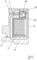
- the electromagnetic brake 1 has, in a manner known per se, an electromagnet 2, a permanent magnet 3 and an armature plate 4 which interacts with the electromagnet 2 and the permanent magnet 3.
- the armature plate 4 is also arranged in a manner known per se in a torsion-proof manner, but nevertheless axially displaceable on a hub body 11.
- the hub body 11 can in turn be mounted on a shaft not shown in the figures.
- the anchor plate 4 is fastened to the hub body 11 with the interposition of a spring element 12.
- the spring element 12 is arranged on the anchor plate 4 by means of rivets 13 and is detachably connected to the hub body 11 by means of screws 14.
- the electromagnet 2 has a magnet housing 5 and a coil 6 accommodated in it.
- the magnet housing 5 is designed in two parts and has a magnet pot 9 on the one hand and a flange 8 that is preferably screwed to it in the final assembled state on the other.
- a cable connection 7 is provided to supply the coil 6 with power.
- the magnet pot 9 On the hub body side, the magnet pot 9 is equipped with a circumferential groove into which an annular scraper 10 is inserted in the final assembled state.
- the magnet housing 5, namely the magnet pot 9, has an outer ring body 15 providing an outer pole and an inner ring body 16 providing an inner pole on the armature plate side.
- a web 17 connecting the inner ring body 16 to the outer ring body 15 is arranged between the inner ring body 16 and the outer ring body 15. This web 17 serves as a magnetic flux bridge between the two poles, ie the outer pole provided by the outer ring body 15 on the one hand and the inner pole provided by the inner ring body 16 on the other.
- the inner ring body 16 carries the permanent magnet 3 on the armature plate side.
- the permanent magnet 3 is provided by a ring body which is aligned parallel to the armature plate 4 with regard to its large sides and can optionally also be designed in several parts.
- the axial dimension of the permanent magnet 3 is therefore smaller than its cross-sectional thickness between its inner diameter and its outer diameter.
- the magnet pot 9 is made of a soft magnetic material.
- Figure 3 Furthermore, the arrows 18 and 19 show the magnetic flux of the permanent magnet 3, namely the magnetic flux 18 via the web 17 and the magnetic flux 19 via the magnet housing 5.
- Figure 3 the armature plate 4 in the open position with the coil 6 de-energized.
- Figure 4 also shows schematically the magnetic flux when the armature plate 4 is open and the coil 6 is de-energized. The resulting magnetic flux is also shown in accordance with arrows 18 and 19.
- Figure 5 shows a schematic representation of a braking or holding process, according to which the armature plate 4 is closed and the coil 6 is de-energized.
- the magnetic flux is set in accordance with the arrows 18 and 19, whereby the proportion of the direct magnetic flux 18 via the web 17 is compared to the open position of the armature plate 4 according to Figure 4 is increased, which is symbolized by the line thickness of arrow 18.
- Figure 6 shows the situation as it occurs when the armature plate 4 is closed and the coil 6 is energized. This results not only in the magnetic flux 18 and 19 due to the permanent magnet 3, but also in a magnetic flux 20 and 21 due to the electromagnet 2. In accordance with the arrows 20 and 21, a magnetic flux 21 is created both via the magnet housing 5 and a magnetic flux 20 via the web 17.
- Figure 6 specifically the release process, whereby an opposite polarity of the coil and permanent magnet circuit occurs in the pole faces and in the long magnetic circuit and a same polarity in the short magnetic circuit.
Landscapes
- Engineering & Computer Science (AREA)
- General Engineering & Computer Science (AREA)
- Physics & Mathematics (AREA)
- Electromagnetism (AREA)
- Mechanical Engineering (AREA)
- Braking Arrangements (AREA)
- Electromagnets (AREA)
Priority Applications (1)
| Application Number | Priority Date | Filing Date | Title |
|---|---|---|---|
| EP24162237.2A EP4357634A3 (fr) | 2022-03-17 | 2022-03-17 | Frein ou embrayage électromagnétique |
Applications Claiming Priority (2)
| Application Number | Priority Date | Filing Date | Title |
|---|---|---|---|
| EP24162237.2A EP4357634A3 (fr) | 2022-03-17 | 2022-03-17 | Frein ou embrayage électromagnétique |
| EP22162800.1A EP4246008B1 (fr) | 2022-03-17 | 2022-03-17 | Frein ou embrayage électromagnétique |
Related Parent Applications (2)
| Application Number | Title | Priority Date | Filing Date |
|---|---|---|---|
| EP22162800.1A Division-Into EP4246008B1 (fr) | 2022-03-17 | 2022-03-17 | Frein ou embrayage électromagnétique |
| EP22162800.1A Division EP4246008B1 (fr) | 2022-03-17 | 2022-03-17 | Frein ou embrayage électromagnétique |
Publications (2)
| Publication Number | Publication Date |
|---|---|
| EP4357634A2 true EP4357634A2 (fr) | 2024-04-24 |
| EP4357634A3 EP4357634A3 (fr) | 2024-05-15 |
Family
ID=80786983
Family Applications (2)
| Application Number | Title | Priority Date | Filing Date |
|---|---|---|---|
| EP24162237.2A Pending EP4357634A3 (fr) | 2022-03-17 | 2022-03-17 | Frein ou embrayage électromagnétique |
| EP22162800.1A Active EP4246008B1 (fr) | 2022-03-17 | 2022-03-17 | Frein ou embrayage électromagnétique |
Family Applications After (1)
| Application Number | Title | Priority Date | Filing Date |
|---|---|---|---|
| EP22162800.1A Active EP4246008B1 (fr) | 2022-03-17 | 2022-03-17 | Frein ou embrayage électromagnétique |
Country Status (2)
| Country | Link |
|---|---|
| US (1) | US11982323B2 (fr) |
| EP (2) | EP4357634A3 (fr) |
Families Citing this family (2)
| Publication number | Priority date | Publication date | Assignee | Title |
|---|---|---|---|---|
| JP7749036B2 (ja) * | 2024-01-11 | 2025-10-03 | ケーイービー オートメーション ケージー | 永久磁石ブレーキ |
| DE102024132451B3 (de) * | 2024-11-07 | 2025-12-04 | Kendrion (Villingen) Gmbh | Elektromagnetisches Erregersystem, elektromagnetische Bremse oder Kupplung und Verfahren zum Herstellen eines elektromagnetischen Erregersystems |
Citations (4)
| Publication number | Priority date | Publication date | Assignee | Title |
|---|---|---|---|---|
| EP1848898B1 (fr) | 2005-02-15 | 2008-04-16 | Kendrion Binder Magnete GmbH | Frein electromagnetique comportant un aimant permanent |
| US20120111690A1 (en) | 2010-11-05 | 2012-05-10 | Yoshihiro Kurosu | Electromagnetic clutch |
| DE102014109125B4 (de) | 2014-06-30 | 2016-09-29 | Kendrion (Villingen) Gmbh | Elektromagnetische Polreibungskupplung oder Polreibungsbremse |
| KR20190075314A (ko) | 2017-12-21 | 2019-07-01 | 현대자동차주식회사 | 전자석 클러치용 필드코어 유닛 |
Family Cites Families (8)
| Publication number | Priority date | Publication date | Assignee | Title |
|---|---|---|---|---|
| US3314512A (en) * | 1965-07-02 | 1967-04-18 | Borg Warner | Coupling device employing flexible hub assembly |
| US4604522A (en) | 1984-11-05 | 1986-08-05 | Halliburton Company | Method and apparatus for logging a borehole employing dual radiation detectors |
| JP2002070892A (ja) * | 2000-08-31 | 2002-03-08 | Mitsubishi Heavy Ind Ltd | 電磁クラッチおよび該電磁クラッチを備えた圧縮機 |
| DE10158732B4 (de) * | 2001-11-30 | 2008-11-27 | Linnig Trucktec Gmbh | Antriebsorgan für eine Wasserpumpe des Kühlwasserkreislaufes eines Verbrennungsmotors sowie Reibschaltkupplung |
| WO2006122517A2 (fr) * | 2005-05-19 | 2006-11-23 | Luk Lamellen Und Kupplungsbau Beteiligungs Kg | Embrayage a friction magnetique |
| JP4939877B2 (ja) * | 2006-09-05 | 2012-05-30 | 三井金属アクト株式会社 | 開閉体の駆動装置 |
| JP5238592B2 (ja) * | 2008-06-18 | 2013-07-17 | 小倉クラッチ株式会社 | 電磁クラッチ |
| DE102009033178A1 (de) * | 2009-07-13 | 2011-01-27 | Licos Trucktec Gmbh | Elektromagnetische Reibschaltkupplung |
-
2022
- 2022-03-17 EP EP24162237.2A patent/EP4357634A3/fr active Pending
- 2022-03-17 EP EP22162800.1A patent/EP4246008B1/fr active Active
-
2023
- 2023-03-17 US US18/122,765 patent/US11982323B2/en active Active
Patent Citations (4)
| Publication number | Priority date | Publication date | Assignee | Title |
|---|---|---|---|---|
| EP1848898B1 (fr) | 2005-02-15 | 2008-04-16 | Kendrion Binder Magnete GmbH | Frein electromagnetique comportant un aimant permanent |
| US20120111690A1 (en) | 2010-11-05 | 2012-05-10 | Yoshihiro Kurosu | Electromagnetic clutch |
| DE102014109125B4 (de) | 2014-06-30 | 2016-09-29 | Kendrion (Villingen) Gmbh | Elektromagnetische Polreibungskupplung oder Polreibungsbremse |
| KR20190075314A (ko) | 2017-12-21 | 2019-07-01 | 현대자동차주식회사 | 전자석 클러치용 필드코어 유닛 |
Also Published As
| Publication number | Publication date |
|---|---|
| US11982323B2 (en) | 2024-05-14 |
| EP4246008B1 (fr) | 2024-06-12 |
| EP4246008A1 (fr) | 2023-09-20 |
| EP4357634A3 (fr) | 2024-05-15 |
| US20230296140A1 (en) | 2023-09-21 |
Similar Documents
| Publication | Publication Date | Title |
|---|---|---|
| EP1848898B1 (fr) | Frein electromagnetique comportant un aimant permanent | |
| DE102009024868B4 (de) | Elektromagnetische Kupplung | |
| EP0837538B1 (fr) | Générateur à poles à griffes avec aimants permanents | |
| DE102008016277A1 (de) | Elektromagnetisch betätigbare Kupplung sowie Wasserpumpe mit einer elektromagnetisch betätigbaren Kupplung | |
| EP4246008B1 (fr) | Frein ou embrayage électromagnétique | |
| DE102013205174A1 (de) | Verbindungsvorrichtung und Verfahren zur Betätigung einer solchen Verbindungsvorrichtung | |
| DE69920320T2 (de) | Magnetische Brems- und Kupplungseinheit | |
| DE102006034922A1 (de) | Elektromagnetische Stellvorrichtung und Verfahren zu deren Herstellung | |
| DE2135821A1 (de) | Reibungsvorrichtung | |
| DE102008054330A1 (de) | Zweiteiliges Motorgehäuse mit Bajonett-Verbindung | |
| DE112015005764T5 (de) | Elektromagnetische Kupplung | |
| DE102014109125B4 (de) | Elektromagnetische Polreibungskupplung oder Polreibungsbremse | |
| WO1986005028A1 (fr) | Aimant annulaire pour freins moteurs | |
| DE102006031310A1 (de) | Hysteresekupplung | |
| DE102013202459A1 (de) | Haltebremse | |
| DE69933430T2 (de) | Anlasser-schütz mit mehrteiligen magnetkern | |
| DE102006007688B4 (de) | Elektromagnetisch betätigbare Schalteinheit | |
| DE102007014654A1 (de) | Bremsscheibenanordnung | |
| DE102015213740A1 (de) | Elektromagnetische Konusbremse und Personenbeförderungsmittelantrieb | |
| EP2366072B1 (fr) | Frein à actionnement électromagnétique | |
| DE19920543A1 (de) | Elektromagnetisch betätigte Einflächenkupplung oder Einflächenbremse | |
| AT528388B1 (de) | Kupplungsvorrichtung zur drehmomentübertragenden Verbindung zweier Wellen | |
| DE102024132451B3 (de) | Elektromagnetisches Erregersystem, elektromagnetische Bremse oder Kupplung und Verfahren zum Herstellen eines elektromagnetischen Erregersystems | |
| EP4293245B1 (fr) | Embrayage ou frein électromagnétique | |
| DE102019215563A1 (de) | Stator einer elektrischen Maschine |
Legal Events
| Date | Code | Title | Description |
|---|---|---|---|
| PUAI | Public reference made under article 153(3) epc to a published international application that has entered the european phase |
Free format text: ORIGINAL CODE: 0009012 |
|
| STAA | Information on the status of an ep patent application or granted ep patent |
Free format text: STATUS: THE APPLICATION HAS BEEN PUBLISHED |
|
| REG | Reference to a national code |
Ref country code: DE Ref legal event code: R079 Free format text: PREVIOUS MAIN CLASS: F16D0027060000 Ipc: F16D0027000000 |
|
| PUAL | Search report despatched |
Free format text: ORIGINAL CODE: 0009013 |
|
| AC | Divisional application: reference to earlier application |
Ref document number: 4246008 Country of ref document: EP Kind code of ref document: P |
|
| AK | Designated contracting states |
Kind code of ref document: A2 Designated state(s): AL AT BE BG CH CY CZ DE DK EE ES FI FR GB GR HR HU IE IS IT LI LT LU LV MC MK MT NL NO PL PT RO RS SE SI SK SM TR |
|
| AK | Designated contracting states |
Kind code of ref document: A3 Designated state(s): AL AT BE BG CH CY CZ DE DK EE ES FI FR GB GR HR HU IE IS IT LI LT LU LV MC MK MT NL NO PL PT RO RS SE SI SK SM TR |
|
| RIC1 | Information provided on ipc code assigned before grant |
Ipc: F16D 27/06 20060101ALI20240408BHEP Ipc: F16D 27/00 20060101AFI20240408BHEP |
|
| P01 | Opt-out of the competence of the unified patent court (upc) registered |
Effective date: 20240425 |
|
| STAA | Information on the status of an ep patent application or granted ep patent |
Free format text: STATUS: REQUEST FOR EXAMINATION WAS MADE |
|
| 17P | Request for examination filed |
Effective date: 20241114 |
|
| RBV | Designated contracting states (corrected) |
Designated state(s): AL AT BE BG CH CY CZ DE DK EE ES FI FR GB GR HR HU IE IS IT LI LT LU LV MC MK MT NL NO PL PT RO RS SE SI SK SM TR |
|
| STAA | Information on the status of an ep patent application or granted ep patent |
Free format text: STATUS: EXAMINATION IS IN PROGRESS |
|
| 17Q | First examination report despatched |
Effective date: 20250407 |