EP4357667A1 - Beleuchtungseinrichtung für einen kraftfahrzeugscheinwerfer zur erzeugung einer lichtverteilung - Google Patents
Beleuchtungseinrichtung für einen kraftfahrzeugscheinwerfer zur erzeugung einer lichtverteilung Download PDFInfo
- Publication number
- EP4357667A1 EP4357667A1 EP22202973.8A EP22202973A EP4357667A1 EP 4357667 A1 EP4357667 A1 EP 4357667A1 EP 22202973 A EP22202973 A EP 22202973A EP 4357667 A1 EP4357667 A1 EP 4357667A1
- Authority
- EP
- European Patent Office
- Prior art keywords
- light
- optic body
- light beam
- illumination device
- section
- Prior art date
- Legal status (The legal status is an assumption and is not a legal conclusion. Google has not performed a legal analysis and makes no representation as to the accuracy of the status listed.)
- Pending
Links
- 238000005286 illumination Methods 0.000 title claims abstract description 50
- 230000003287 optical effect Effects 0.000 claims abstract description 27
- 230000008878 coupling Effects 0.000 claims description 9
- 238000010168 coupling process Methods 0.000 claims description 9
- 238000005859 coupling reaction Methods 0.000 claims description 9
- 230000004075 alteration Effects 0.000 description 4
- 230000006835 compression Effects 0.000 description 2
- 238000007906 compression Methods 0.000 description 2
- 230000003247 decreasing effect Effects 0.000 description 1
- 230000000694 effects Effects 0.000 description 1
Images

Classifications
-
- F—MECHANICAL ENGINEERING; LIGHTING; HEATING; WEAPONS; BLASTING
- F21—LIGHTING
- F21S—NON-PORTABLE LIGHTING DEVICES; SYSTEMS THEREOF; VEHICLE LIGHTING DEVICES SPECIALLY ADAPTED FOR VEHICLE EXTERIORS
- F21S41/00—Illuminating devices specially adapted for vehicle exteriors, e.g. headlamps
- F21S41/20—Illuminating devices specially adapted for vehicle exteriors, e.g. headlamps characterised by refractors, transparent cover plates, light guides or filters
- F21S41/24—Light guides
-
- F—MECHANICAL ENGINEERING; LIGHTING; HEATING; WEAPONS; BLASTING
- F21—LIGHTING
- F21S—NON-PORTABLE LIGHTING DEVICES; SYSTEMS THEREOF; VEHICLE LIGHTING DEVICES SPECIALLY ADAPTED FOR VEHICLE EXTERIORS
- F21S41/00—Illuminating devices specially adapted for vehicle exteriors, e.g. headlamps
- F21S41/10—Illuminating devices specially adapted for vehicle exteriors, e.g. headlamps characterised by the light source
- F21S41/14—Illuminating devices specially adapted for vehicle exteriors, e.g. headlamps characterised by the light source characterised by the type of light source
- F21S41/141—Light emitting diodes [LED]
- F21S41/143—Light emitting diodes [LED] the main emission direction of the LED being parallel to the optical axis of the illuminating device
-
- F—MECHANICAL ENGINEERING; LIGHTING; HEATING; WEAPONS; BLASTING
- F21—LIGHTING
- F21S—NON-PORTABLE LIGHTING DEVICES; SYSTEMS THEREOF; VEHICLE LIGHTING DEVICES SPECIALLY ADAPTED FOR VEHICLE EXTERIORS
- F21S41/00—Illuminating devices specially adapted for vehicle exteriors, e.g. headlamps
- F21S41/20—Illuminating devices specially adapted for vehicle exteriors, e.g. headlamps characterised by refractors, transparent cover plates, light guides or filters
- F21S41/25—Projection lenses
-
- F—MECHANICAL ENGINEERING; LIGHTING; HEATING; WEAPONS; BLASTING
- F21—LIGHTING
- F21S—NON-PORTABLE LIGHTING DEVICES; SYSTEMS THEREOF; VEHICLE LIGHTING DEVICES SPECIALLY ADAPTED FOR VEHICLE EXTERIORS
- F21S41/00—Illuminating devices specially adapted for vehicle exteriors, e.g. headlamps
- F21S41/30—Illuminating devices specially adapted for vehicle exteriors, e.g. headlamps characterised by reflectors
- F21S41/32—Optical layout thereof
-
- F—MECHANICAL ENGINEERING; LIGHTING; HEATING; WEAPONS; BLASTING
- F21—LIGHTING
- F21S—NON-PORTABLE LIGHTING DEVICES; SYSTEMS THEREOF; VEHICLE LIGHTING DEVICES SPECIALLY ADAPTED FOR VEHICLE EXTERIORS
- F21S41/00—Illuminating devices specially adapted for vehicle exteriors, e.g. headlamps
- F21S41/30—Illuminating devices specially adapted for vehicle exteriors, e.g. headlamps characterised by reflectors
- F21S41/32—Optical layout thereof
- F21S41/322—Optical layout thereof the reflector using total internal reflection
-
- F—MECHANICAL ENGINEERING; LIGHTING; HEATING; WEAPONS; BLASTING
- F21—LIGHTING
- F21S—NON-PORTABLE LIGHTING DEVICES; SYSTEMS THEREOF; VEHICLE LIGHTING DEVICES SPECIALLY ADAPTED FOR VEHICLE EXTERIORS
- F21S41/00—Illuminating devices specially adapted for vehicle exteriors, e.g. headlamps
- F21S41/30—Illuminating devices specially adapted for vehicle exteriors, e.g. headlamps characterised by reflectors
- F21S41/32—Optical layout thereof
- F21S41/33—Multi-surface reflectors, e.g. reflectors with facets or reflectors with portions of different curvature
-
- F—MECHANICAL ENGINEERING; LIGHTING; HEATING; WEAPONS; BLASTING
- F21—LIGHTING
- F21S—NON-PORTABLE LIGHTING DEVICES; SYSTEMS THEREOF; VEHICLE LIGHTING DEVICES SPECIALLY ADAPTED FOR VEHICLE EXTERIORS
- F21S41/00—Illuminating devices specially adapted for vehicle exteriors, e.g. headlamps
- F21S41/30—Illuminating devices specially adapted for vehicle exteriors, e.g. headlamps characterised by reflectors
- F21S41/32—Optical layout thereof
- F21S41/36—Combinations of two or more separate reflectors
- F21S41/365—Combinations of two or more separate reflectors successively reflecting the light
-
- F—MECHANICAL ENGINEERING; LIGHTING; HEATING; WEAPONS; BLASTING
- F21—LIGHTING
- F21V—FUNCTIONAL FEATURES OR DETAILS OF LIGHTING DEVICES OR SYSTEMS THEREOF; STRUCTURAL COMBINATIONS OF LIGHTING DEVICES WITH OTHER ARTICLES, NOT OTHERWISE PROVIDED FOR
- F21V7/00—Reflectors for light sources
- F21V7/04—Optical design
-
- F—MECHANICAL ENGINEERING; LIGHTING; HEATING; WEAPONS; BLASTING
- F21—LIGHTING
- F21V—FUNCTIONAL FEATURES OR DETAILS OF LIGHTING DEVICES OR SYSTEMS THEREOF; STRUCTURAL COMBINATIONS OF LIGHTING DEVICES WITH OTHER ARTICLES, NOT OTHERWISE PROVIDED FOR
- F21V7/00—Reflectors for light sources
- F21V7/04—Optical design
- F21V7/06—Optical design with parabolic curvature
-
- G—PHYSICS
- G02—OPTICS
- G02B—OPTICAL ELEMENTS, SYSTEMS OR APPARATUS
- G02B19/00—Condensers, e.g. light collectors or similar non-imaging optics
- G02B19/0004—Condensers, e.g. light collectors or similar non-imaging optics characterised by the optical means employed
- G02B19/0028—Condensers, e.g. light collectors or similar non-imaging optics characterised by the optical means employed refractive and reflective surfaces, e.g. non-imaging catadioptric systems
-
- G—PHYSICS
- G02—OPTICS
- G02B—OPTICAL ELEMENTS, SYSTEMS OR APPARATUS
- G02B19/00—Condensers, e.g. light collectors or similar non-imaging optics
- G02B19/0033—Condensers, e.g. light collectors or similar non-imaging optics characterised by the use
- G02B19/0047—Condensers, e.g. light collectors or similar non-imaging optics characterised by the use for use with a light source
-
- F—MECHANICAL ENGINEERING; LIGHTING; HEATING; WEAPONS; BLASTING
- F21—LIGHTING
- F21W—INDEXING SCHEME ASSOCIATED WITH SUBCLASSES F21K, F21L, F21S and F21V, RELATING TO USES OR APPLICATIONS OF LIGHTING DEVICES OR SYSTEMS
- F21W2102/00—Exterior vehicle lighting devices for illuminating purposes
- F21W2102/10—Arrangement or contour of the emitted light
- F21W2102/13—Arrangement or contour of the emitted light for high-beam region or low-beam region
Definitions
- the invention relates to an illumination device for a motor vehicle headlamp for generating a light distribution, said illumination device comprises:
- the invention relates to a motor vehicle headlamp comprising an illumination device.
- illumination devices for use in a motor vehicle headlamp for generating a light distribution are well known.
- a light source creates and emits light, which is guided to an optical system via an optic body, e.g. a light guide.
- the optical system is configured to create a specific light function or light distribution (e.g. a low beam light distribution, a high beam light distribution, etc.) with the light received from the light source via the optic body.
- optic bodies usually are planar light guides, configured to guide light to a specific location, e.g. a light input surface of the optical system.
- planar light guides can also compensate for an off-axis arrangement of the light source and the optical system, wherein such arrangement is due to the design of the illumination device or the headlamp which uses the illumination device. Due to their characteristics, planar light guides are not able to affect the size and the divergency of light beams or light rays which are guided through the light guide. Therefore, the possible light output from a planar light guide is rather limited. In order to modify the size and divergency of light beams, usually, additional optical elements such as lenses are being used.
- the optic body comprises a first pair of optically operative surfaces for guiding the light beam coupled into the optic body via the light input section along a first light beam path from the light input section to the light output section,
- the illumination device has the advantage, that the light beam gets broadened (or widened) while travelling through the optic body, therefore the divergence of the light beam can be decreased, which can reduce unwanted optical effects, e.g. chromatic aberration.
- the optic body acts as a so-called beam expander, because the diameter of the light beam is expanded while travelling through the optic body.
- the first pair of optically operative surfaces can also be described as paraboloids or truncated paraboloids (in 3D). Divergency can by understood as essentially an angle between adjacent light rays along the direction of light propagation.
- Divergency can also be described as a beam divergence, which can be described as an angular measure of the increase in beam diameter or radius with distance from an element (e.g. a light source) from which the beam emerges.
- Beam divergence usually refers to a beam of circular cross section.
- a beam may, for example, also have an elliptical cross section, in which case the orientation of the beam divergence has to be specified, for example with respect to the major or minor axis of the elliptical cross section.
- the optical system in particular the at least one optical element, is configured to invert (along a vertical axis or plane) the light pattern received from the optic body. In general, if the beam diameter gets wider, divergence gets lower.
- the light source is configured to emit a second light beam
- the optic body comprises a second pair of optically operative surfaces for guiding the second light beam coupled into the optic body via the light input section along a second light beam path from the light input section to the light output section, wherein the second light beam has a third vertical extent in the main vertical cross section, when being coupled into the optic body,
- the first pair of optically operative surfaces can act as a beam expander and the second pair of optically operative surfaces can act as a beam compressor, wherein the expander broadens the cross section of a first portion of the light beam (i.e. the at least one light beam) and the compressor narrows the cross section of a second portion of the light beam (i.e. the second light beam).
- a first portion of the total light beam being emitted by the light source can be compressed while a second portion of the total light beam can be expanded, wherein the expansion and the compression can be achieved by the first and second part of optically operative surfaces respectively.
- the first, second, third and fourth light deflection surface are arranged in such a way, that a fictional plane, which intersects the common first focal point and the common second focal point, intersects the optic body at an intersection line, wherein the optical body is configured in such a way that the first light deflection surface lies vertically higher relative to the intersection line than the third light deflection surface.
- the generated light distribution comprises a first partial light distribution and a second partial light distribution, wherein the at least one light beam coupled out of the first light exit surface forms the first partial light distribution, wherein the second light beam coupled out of the second light exit surface forms the second partial light distribution.
- the expanded light beam is used to form the first partial light distribution and the compressed light beam is used to form the second partial light distribution.
- the generated light distribution is a low beam light distribution, wherein a vertical extension of the low beam light distribution extends along a VV-line from at least 0° down to at least -10° on the VV-line.
- a center of the first partial light distribution is closer to the 0° line of the VV-line than a center of the second partial light distribution.
- the first pair of optically operative surfaces and the second pair of optically operative surfaces can be arranged in such a way, that a center of the second partial light distribution is closer to the 0° line of the VV-line than a center of the first partial light distribution.
- the vertically higher light distribution can be created by the compressed or the expanded light beam, depending on the arrangement of the first and second pair of optically operative surfaces.
- the first and third light deflection surface are arranged on a same side of the shell surface of the optic body.
- the second and forth light deflection surface are arranged on a same side of the shell surface of the optic body.
- first and second light deflection surface have a concave curvature and the third and fourth light deflection surface have a convex curvature.
- Advantageously light rays forming the at least one light beam have a first divergence in the main vertical cross section along the main direction, wherein the light rays forming the at least one light beam after being coupled out of the optic body have a second divergence in the main vertical cross section, wherein said second divergence is smaller than the first divergence.
- Advantageously light rays forming the second light beam have a third divergence in the main vertical cross section along the main direction, wherein the light rays forming the second light beam after being coupled out of the optic body have a fourth divergence in the main vertical cross section, wherein said fourth divergence is greater than the third divergence.
- the fourth divergence (of the compressed, second light beam) is also greater than the second divergence of the at least one (or first) light beam.
- the lower (or smaller), second divergence is the result of the wider (expanded) at least one light beam. As a result, the at least one light beam is hitting the projection lens at smaller angles and thus the chromatic aberration or other color effects are reduced.
- a motor vehicle headlamp comprising an illumination device.
- Fig. 1 shows a schematic side view of an optic body 3 of a first embodiment of an illumination device 1 for a motor vehicle headlamp.
- Fig. 2 shows an optic body 3 of a second embodiment, described in more detail below.
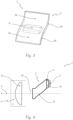
- a perspective view of the optic body according to the second embodiment is shown in Fig. 3 .
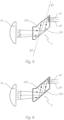
- the illumination device 1 (as seen on Fig. 4 ) comprises a light source 2 configured to emit at least one light beam in a main direction X of the illumination device 1.
- the optic body 3 is arranged downstream of the light source 2 along the main direction X.
- Fig. 1 shows a schematic view of the optic body 3, which comprises a light input section 3a for coupling the light beam (indicated by the hatched arrow) from the light source 2 into the optic body 3.
- the light input section 3a comprises a light collecting element 4 (seen in Fig. 4 ), which is assigned to the light source 2 and is configured to couple the light beam from the assigned light source 2 into the optic body 3 in such a way, that light rays forming the light beam are essentially parallel to each other and essentially parallel to the main direction X after being coupled into the optic body 3.
- the parallel light beam has a first vertical extent v1' in a main vertical cross section v - seen in a correct installed state of the illumination device 1 in a vehicle -, when being coupled into the optic body 3, said main vertical cross section v is parallel to the main direction X.
- the optic body 3 comprises a light output section 3b for decoupling the light beam coupled into the optic body 3 via the light input section 3a, out of the optic body 3 in the main direction X.
- the optic body 3 further comprises a shell surface 3c limiting the optic body 3, said shell surface 3c is configured to deflect the light beam coupled into the optic body 3.
- the shell surface 3c extends between the light input section 3a and the light output section 3b.
- the illumination device 1 comprises an optical system 5, comprising at least one optical element 5a, arranged downstream of the optic body 3 along the main direction X in order to receive the light beam emitted from the light output section 3b of the optic body 3.
- the optical system 5 is configured to project the light beam in front of the illumination device 1.
- the optical system 5 in combination with the light source 2 and the optic body 3 are configured to generate the light distribution.
- the generated light distribution can be a low beam light distribution, wherein a vertical extension of the low beam light distribution extends along a VV-line from at least 0° down to at least -10° on the VV-line.
- the optic body 3 comprises a first pair of optically operative surfaces 6 for guiding the light beam coupled into the optic body 3 via the light input section 3a along a first light beam path LB1 from the light input section 3a to the light output section 3b.
- the first pair of optically operative surfaces 6 consists of a first and second light deflection surface 6a, 6b, wherein the first and second light deflection surfaces 6a, 6b are arranged on the shell surface 3c.
- the optic body 3 comprises a first and a second side arranged opposite to each other, wherein the first light deflection surface 6a is arranged on the first side and the second light deflection surface 6b is arranged on the second side of the optic body 3.
- the first light deflection surface 6a follows a first parabola
- the second light deflection surface 6b follows a second parabola
- the first and second light deflection surfaces 6a, 6b are arranged on the shell surface 3c in such a way that the first and second parabola have a common first focal point fp1.
- the light beam following the first light beam path LB1 is incident on the first light deflection surface 6a and is deflected to the second light deflection surface 6b.
- the deflected light beam is incident on the second light deflection surface 6b and is deflected to the light output section 3b for coupling out of the optic body 3.
- the light output section 3b comprises a first light exit surface 7a, wherein the first pair of optically operative surfaces 6 and the light output section 3b are arranged in such a way, that the light beam deflected by the second light deflection surface 6b is incident on the first light exit surface 7a.
- the first and second light deflection surfaces 6a, 6b and the first light exit surface 7a are configured in such a way, that light rays forming the light beam are essentially parallel to each other and essentially parallel to the main direction X after being coupled out of the optic body 3.
- the outcoupled parallel light beam has a second vertical extent v2' in the main vertical cross section v, said second vertical extent v2' is greater than the first vertical extent v1'. This is indicated in the broader hatched arrow on the left side of the optical body 3.
- the optic body 3 acts as a beam expander in the embodiment shown in Fig. 1 .
- the light source 2 is configured to emit a second light beam (or a light beam comprising two portions) and the optic body 3 comprises a second pair of optically operative surfaces 8 for guiding the second light beam coupled into the optic body 3 via the light input section 3a along a second light beam path LB2 from the light input section 3a to the light output section 3b.
- the second light beam has a third vertical extent v3 in the main vertical cross section v, when being coupled into the optic body 3.
- the second light beam is depicted by a black arrow.
- the second pair of optically operative surfaces 8 consists of a third and fourth light deflection surface 8a, 8b.
- the third and fourth light deflection surfaces 8a, 8b are arranged on the shell surface 3c.
- the third light deflection surface 8a is arranged on the first side and the forth light deflection surface 8b is arranged on the second side of the optic body 3.
- the third light deflection surface 8a follows a third parabola and the forth light deflection surface 8b follows a forth parabola.
- the third and fourth light deflection surfaces 8a, 8b are arranged on the shell surface 3c in such a way, that the third and fourth parabola have a common second focal point fp2.
- the second light beam following the second light beam path LB2 is incident on the third light deflection surface 8a and is deflected to the forth light deflection surface 8b, and the deflected second light beam is incident on the forth light deflection surface 8b and is deflected to the light output section 3b for coupling out of the optic body 3.
- the light output section 3b comprises a second light exit surface 7b.
- the second pair of optically operative surfaces 8 and the light output section 3b are arranged in such a way, that the light beam deflected by the fourth light deflection surface 8b is incident on the second light exit surface 7b.
- the third and fourth light deflection surfaces 8a, 8b are configured in such a way, that light rays of the second light beam are essentially parallel to each other and essentially parallel to the main direction X after being coupled out of the optic body 3.
- the outcoupled essentially parallel light beam has a forth vertical extent v4 in the main vertical cross section v, said forth vertical extent v4 is smaller than the third vertical extent v3.
- the optic body 3 acts as a beam expander and at the same time as beam compressor in the embodiment shown in Fig. 1 .
- the first, second, third and fourth light deflection surface 6a, 6b, 8a, 8b are arranged in such a way, that a fictional plane, which intersects the common first focal point fp1 and the common second focal point fp2, intersects the optic body 3 at an intersection line.
- the optical body 3 is configured in such a way that the first light deflection surface 6a lies vertically higher on the intersection line than the third light deflection surface 8a.
- the first and third light deflection surface 6a, 8a are arranged on a same side of the shell surface 3c of the optic body 3.
- the second and forth light deflection surface 6b, 8b are arranged on a same side of the shell surface 3c of the optic body 3.
- the first and second light deflection surface 6a, 6b have a concave curvature and the third and fourth light deflection surface 8a, 8b have a convex curvature.
- Fig. 3 shows a perspective view of the optic body 3 of the second embodiment, wherein the dotted box depicts the actual optic body 3, which is a cut-out of the first pair of optically operative surfaces 6 and the second pair of optically operative surfaces 8.
- Fig. 5 shows the second embodiment of the illumination device 1.
- Fig. 5 shows the illumination device according to Fig. 4 , wherein the light beam paths LB1 and LB2 are indicated.
- the upper, at least one light beam has a divergence d1 prior to entering the optic body 3.
- the at least one light beam After the at least one light beam exits the optic body 3, the at least one light beam has a divergence d2, which is smaller than the initial divergence d1, due to the widening or expansion of the at least one light beam while traveling through the optic body 3 along the beam path LB1.
- the lower, second light beam has a divergence d3 prior to entering the optic body 3.
- the second light beam has a divergence d4, which is greater than the initial divergence d3, due to the compression of the second light beam while traveling through the optic body 3 along the beam path LB2.
- the divergence d4 of the second (lower) light beam is also greater than the divergence d2 of the at least one light beam (the upper, first light beam).
- the upper light beam hitting the optical element 5a has a reduced chromatic aberration.
- Fig. 6 shows a prior art illumination device having a standard planar optic body 3'.
- the upper light beam has a divergence d1' prior to entering the optic body 3'.
- the upper light beam has a divergence d2', which is equal to the initial divergence d1'.
- the divergence of the upper light beam remains unchanged while traveling through the optic body 3' along the beam path LB1'.
- the lower light beam has a divergence d3' prior to entering the optic body 3'.
- the lower light beam After the lower light beam exits the optic body 3', the lower light beam has a divergence d4', which is equal to the initial divergence d3'.
Landscapes
- Engineering & Computer Science (AREA)
- General Engineering & Computer Science (AREA)
- Physics & Mathematics (AREA)
- Optics & Photonics (AREA)
- Microelectronics & Electronic Packaging (AREA)
- General Physics & Mathematics (AREA)
- Non-Portable Lighting Devices Or Systems Thereof (AREA)
Priority Applications (4)
| Application Number | Priority Date | Filing Date | Title |
|---|---|---|---|
| EP22202973.8A EP4357667A1 (de) | 2022-10-21 | 2022-10-21 | Beleuchtungseinrichtung für einen kraftfahrzeugscheinwerfer zur erzeugung einer lichtverteilung |
| JP2023172333A JP7702461B2 (ja) | 2022-10-21 | 2023-10-03 | 光分布生成のための自動車前照灯用照明装置 |
| US18/379,735 US11953170B1 (en) | 2022-10-21 | 2023-10-13 | Illumination device for motor vehicle headlamp for generating light distribution |
| CN202311372972.9A CN118309953A (zh) | 2022-10-21 | 2023-10-20 | 照明装置和包括照明装置的机动车辆的前照灯 |
Applications Claiming Priority (1)
| Application Number | Priority Date | Filing Date | Title |
|---|---|---|---|
| EP22202973.8A EP4357667A1 (de) | 2022-10-21 | 2022-10-21 | Beleuchtungseinrichtung für einen kraftfahrzeugscheinwerfer zur erzeugung einer lichtverteilung |
Publications (1)
| Publication Number | Publication Date |
|---|---|
| EP4357667A1 true EP4357667A1 (de) | 2024-04-24 |
Family
ID=83902830
Family Applications (1)
| Application Number | Title | Priority Date | Filing Date |
|---|---|---|---|
| EP22202973.8A Pending EP4357667A1 (de) | 2022-10-21 | 2022-10-21 | Beleuchtungseinrichtung für einen kraftfahrzeugscheinwerfer zur erzeugung einer lichtverteilung |
Country Status (4)
| Country | Link |
|---|---|
| US (1) | US11953170B1 (de) |
| EP (1) | EP4357667A1 (de) |
| JP (1) | JP7702461B2 (de) |
| CN (1) | CN118309953A (de) |
Families Citing this family (1)
| Publication number | Priority date | Publication date | Assignee | Title |
|---|---|---|---|---|
| EP4703628A1 (de) * | 2024-08-30 | 2026-03-04 | ZKW Group GmbH | Beleuchtungseinrichtung für ein fahrzeug |
Citations (4)
| Publication number | Priority date | Publication date | Assignee | Title |
|---|---|---|---|---|
| WO2015170071A1 (en) * | 2014-05-07 | 2015-11-12 | Bae Systems Plc | Optical device |
| DE102017117560A1 (de) * | 2017-08-02 | 2019-02-07 | Automotive Lighting Reutlingen Gmbh | Lichtmodul und Verfahren zum Betreiben des Lichtmoduls |
| US10288248B1 (en) * | 2017-12-14 | 2019-05-14 | Valeo North America, Inc. | Device for automotive lighting |
| US20220186902A1 (en) * | 2020-12-10 | 2022-06-16 | Hyundai Motor Company | Slim type lamp apparatus for vehicle |
Family Cites Families (6)
| Publication number | Priority date | Publication date | Assignee | Title |
|---|---|---|---|---|
| JP4540013B2 (ja) | 2008-09-04 | 2010-09-08 | 千洋 鈴木 | 平行光出力ユニット、プロジェクタ、および立体像表示ユニット |
| JP5475395B2 (ja) * | 2009-10-23 | 2014-04-16 | スタンレー電気株式会社 | 車両用灯具 |
| FR3023600B1 (fr) | 2014-07-11 | 2021-04-16 | Valeo Vision | Module lumineux d'un vehicule automobile |
| KR102594702B1 (ko) * | 2016-11-03 | 2023-10-26 | 현대모비스 주식회사 | 차량용 라이트 가이드 유닛 |
| AT519119B1 (de) | 2016-11-22 | 2018-04-15 | Zkw Group Gmbh | Beleuchtungseinrichtung eines kraftfahrzeugscheinwerfers |
| EP3473918B1 (de) | 2017-10-19 | 2021-12-01 | ZKW Group GmbH | Beleuchtungsvorrichtung für einen kraftfahrzeugscheinwerfer |
-
2022
- 2022-10-21 EP EP22202973.8A patent/EP4357667A1/de active Pending
-
2023
- 2023-10-03 JP JP2023172333A patent/JP7702461B2/ja active Active
- 2023-10-13 US US18/379,735 patent/US11953170B1/en active Active
- 2023-10-20 CN CN202311372972.9A patent/CN118309953A/zh active Pending
Patent Citations (4)
| Publication number | Priority date | Publication date | Assignee | Title |
|---|---|---|---|---|
| WO2015170071A1 (en) * | 2014-05-07 | 2015-11-12 | Bae Systems Plc | Optical device |
| DE102017117560A1 (de) * | 2017-08-02 | 2019-02-07 | Automotive Lighting Reutlingen Gmbh | Lichtmodul und Verfahren zum Betreiben des Lichtmoduls |
| US10288248B1 (en) * | 2017-12-14 | 2019-05-14 | Valeo North America, Inc. | Device for automotive lighting |
| US20220186902A1 (en) * | 2020-12-10 | 2022-06-16 | Hyundai Motor Company | Slim type lamp apparatus for vehicle |
Also Published As
| Publication number | Publication date |
|---|---|
| US20240133529A1 (en) | 2024-04-25 |
| CN118309953A (zh) | 2024-07-09 |
| US20240230043A9 (en) | 2024-07-11 |
| JP7702461B2 (ja) | 2025-07-03 |
| US11953170B1 (en) | 2024-04-09 |
| JP2024061637A (ja) | 2024-05-07 |
Similar Documents
| Publication | Publication Date | Title |
|---|---|---|
| KR102293083B1 (ko) | 자동차 헤드램프용 조명 장치 및 자동차 헤드램프 | |
| EP4419833B1 (de) | Beleuchtungsvorrichtung für ein fahrzeug-scheinwerfer | |
| KR102902835B1 (ko) | 디퓨저 기기 | |
| US20200256540A1 (en) | Lighting device for vehicles | |
| US20160274369A1 (en) | Laser beam combining device | |
| US11953170B1 (en) | Illumination device for motor vehicle headlamp for generating light distribution | |
| US20020051360A1 (en) | Method and apparatus for unifying light beams | |
| US20250383058A1 (en) | Lighting Device for a Vehicle | |
| KR102764805B1 (ko) | 자동차 헤드라이트용 광학 시스템 | |
| US12601455B2 (en) | Lighting device for a motor vehicle | |
| US20210294098A1 (en) | Image display device | |
| US20180292063A1 (en) | Optical assembly comprising reflectors provided with discontinuities | |
| JP7771327B2 (ja) | 自動車投光器用の照射装置並びに自動車投光器 | |
| WO2022171693A1 (en) | Light emitting module for vehicle, vehicle headlamp and vehicle | |
| EP4703628A1 (de) | Beleuchtungseinrichtung für ein fahrzeug | |
| US11906127B2 (en) | Signal lights for a motor vehicle lighting system | |
| KR102608027B1 (ko) | 고해상도 차량 헤드램프 | |
| EP4180710A1 (de) | Beleuchtungsvorrichtung für kraftfahrzeugscheinwerfer | |
| CN120027384A (zh) | 用于机动车前照灯的照明装置以及机动车前照灯 | |
| JPH10333067A (ja) | マルチビーム走査光学系およびマルチビーム走査光学系用のカップリング光学系 |
Legal Events
| Date | Code | Title | Description |
|---|---|---|---|
| PUAI | Public reference made under article 153(3) epc to a published international application that has entered the european phase |
Free format text: ORIGINAL CODE: 0009012 |
|
| STAA | Information on the status of an ep patent application or granted ep patent |
Free format text: STATUS: THE APPLICATION HAS BEEN PUBLISHED |
|
| AK | Designated contracting states |
Kind code of ref document: A1 Designated state(s): AL AT BE BG CH CY CZ DE DK EE ES FI FR GB GR HR HU IE IS IT LI LT LU LV MC ME MK MT NL NO PL PT RO RS SE SI SK SM TR |
|
| STAA | Information on the status of an ep patent application or granted ep patent |
Free format text: STATUS: REQUEST FOR EXAMINATION WAS MADE |
|
| 17P | Request for examination filed |
Effective date: 20241003 |
|
| RBV | Designated contracting states (corrected) |
Designated state(s): AL AT BE BG CH CY CZ DE DK EE ES FI FR GB GR HR HU IE IS IT LI LT LU LV MC ME MK MT NL NO PL PT RO RS SE SI SK SM TR |