EP4359623B1 - Truelle de lissage à longue durée de vie - Google Patents
Truelle de lissage à longue durée de vie Download PDFInfo
- Publication number
- EP4359623B1 EP4359623B1 EP22786286.9A EP22786286A EP4359623B1 EP 4359623 B1 EP4359623 B1 EP 4359623B1 EP 22786286 A EP22786286 A EP 22786286A EP 4359623 B1 EP4359623 B1 EP 4359623B1
- Authority
- EP
- European Patent Office
- Prior art keywords
- smoothing
- trowel
- blade
- handle
- bolts
- Prior art date
- Legal status (The legal status is an assumption and is not a legal conclusion. Google has not performed a legal analysis and makes no representation as to the accuracy of the status listed.)
- Active
Links
Images


Classifications
-
- B—PERFORMING OPERATIONS; TRANSPORTING
- B25—HAND TOOLS; PORTABLE POWER-DRIVEN TOOLS; MANIPULATORS
- B25G—HANDLES FOR HAND IMPLEMENTS
- B25G3/00—Attaching handles to the implements
- B25G3/34—Attaching handles to the implements by pressing the handle on the implements; using cement or molten metal, e.g. casting, moulding, by welding or the like
-
- E—FIXED CONSTRUCTIONS
- E04—BUILDING
- E04F—FINISHING WORK ON BUILDINGS, e.g. STAIRS, FLOORS
- E04F21/00—Implements for finishing work on buildings
- E04F21/02—Implements for finishing work on buildings for applying plasticised masses to surfaces, e.g. plastering walls
- E04F21/16—Implements for after-treatment of plaster or the like before it has hardened or dried, e.g. smoothing-tools, profile trowels
- E04F21/161—Trowels
-
- E—FIXED CONSTRUCTIONS
- E04—BUILDING
- E04F—FINISHING WORK ON BUILDINGS, e.g. STAIRS, FLOORS
- E04F21/00—Implements for finishing work on buildings
- E04F21/20—Implements for finishing work on buildings for laying flooring
- E04F21/24—Implements for finishing work on buildings for laying flooring of masses made in situ, e.g. smoothing tools
- E04F21/241—Elongated smoothing blades or plates, e.g. screed apparatus
-
- E—FIXED CONSTRUCTIONS
- E04—BUILDING
- E04G—SCAFFOLDING; FORMS; SHUTTERING; BUILDING IMPLEMENTS OR AIDS, OR THEIR USE; HANDLING BUILDING MATERIALS ON THE SITE; REPAIRING, BREAKING-UP OR OTHER WORK ON EXISTING BUILDINGS
- E04G21/00—Preparing, conveying, or working-up building materials or building elements in situ; Other devices or measures for constructional work
- E04G21/14—Conveying or assembling building elements
- E04G21/16—Tools or apparatus
- E04G21/20—Tools or apparatus for applying mortar
- E04G21/201—Trowels
Definitions
- the present invention relates to a tool that can be used for spreading and smoothing building materials, particularly plaster and mortar. It is typically used for plastering.
- the tool is generally referred to here as a smoothing trowel.
- the invention equally relates to spatulas, in particular also surface spatulas, painter's spatulas, and plaster filler knives, as well as, in individual cases, squeegees.
- the invention also relates to corner trowels, inside corner trowels and outside corner trowels, mortar trowels, and point trowels, each in toothed and untoothed versions.
- the utility model DE 1 754 183 discloses a smoothing trowel whose main elements are the blade, a handle support, and the handle.
- the handle support is attached to a bar that stabilizes the blade.
- it can be advantageous to manufacture all three parts in one piece from plastic. This also avoids the difficulty of creating a reliable connection, as the mechanical stress on the trowels and contact with mortar can weaken connections over time.
- the disclosure document DE 1 684 410 discloses a bricklayer's trowel with a soldered joint between the blade and the handle support.
- the soldered joint is intended to improve the strength of the connection between the handle and the blade.
- the solder is introduced into holes in the sole plate of the handle, which are additionally provided with extensions at the end facing the blade. This solution may have proven successful for various trowels. However, it seems desirable to to have more freedom in the design and choice of materials for the handle support and trowel blade, and to be able to offer alternatives to the solder connection.
- the disclosure document DE 25 40 885 discloses a smoothing trowel or "smoothing chip" for plastering with a movable and replaceable handle.
- a guide rail is provided on the smoothing blade, to which the handle is attached.
- the guide rail is welded to the steel smoothing blade.
- the patent application DE 3639978 discloses a bricklayer's trowel in which the handle is positioned behind the blade and connected to the blade by a curved piece of tubing, the so-called tang.
- the attachment between the tang and the blade is to be achieved by welding.
- This design may produce a very durable connection, but it is not very suitable for other trowel shapes, such as those in which the handle is located above the center of the blade.
- the US Patent 9,784,000 discloses that bolts can be welded onto the top of the trowel blade and a handle can be attached via these bolts.
- US2005034262A1 discloses a smoothing trowel according to the preamble of claim 1 and a method according to steps a. to e. of claim 8.
- the invention aims to overcome the disadvantages of the prior art. It aims to provide a durable and robust smoothing trowel that can also be produced efficiently.
- smoothing trowel is also to be understood as a term used to describe related tools used for spreading building materials, especially those exemplified above with typical names.
- a smoothing trowel comprises at least one smoothing blade and a handle.
- the smoothing blade is usually a completely or predominantly flat surface, allowing it to be used for smoothing on a single level across the entire surface. Exceptions are corner trowels for internal or external corners/edges, where the smoothing blade is curved so that the two main working surfaces are at a 90° angle to each other.
- a handle holder connects the handle to the smoothing blade.
- the handle holder can be a separate component, or alternatively, it could be made integrally with the handle or the smoothing blade.
- the handle holder can be conveniently made of a metal, such as steel, stainless steel, or aluminum. It is particularly suitable to manufacture the handle holder as a cast component, preferably as a die-cast aluminum component.
- the handle holder could also be made of plastic, even using an injection molding process.
- the handle holder should be connected to the smoothing blade with a plurality of bolts.
- “Plurality” here means at least two bolts, but between four and ten bolts are often used.
- the bolts are preferably made of metal, such as steel, stainless steel, or aluminum. A metal that is easy to weld is advantageous. It is also possible to weld the bolts to the handle holder. It may also be advantageous to screw the bolts. It may be advisable to select the bolt material so that a press fit can be achieved.
- Trowels are available in which the first and last bolts in a connecting row are thicker than the other bolts. Since the first and last bolts are subject to greater stress than the other bolts, this can offer advantages. However, the present invention allows for a secure and permanent connection without requiring the first and last bolts to be thicker.
- recesses are to be provided in the smoothing blade.
- These recesses can be round holes, for example.
- the bolts are inserted into these recesses. This means that the bolts are not meant to rest on the smoothing blade, but are at least partially guided through it.
- This type of connection geometry unlike conventional bolted connections, results in a stronger and more durable bond.
- a smoothing trowel is often used for several years, sometimes even for more than a decade. It is exposed to high mechanical stress, particularly because at least the smoothing blade typically has a certain degree of elasticity. It is also exposed to chemical stress, particularly when in contact with alkaline mortar or plaster.
- the bolts are welded to the screed blade.
- Laser welding also known as laser beam welding, is particularly suitable for connecting the bolts to the smoothing plate. It can be used as heat conduction welding or deep penetration welding. In individual cases, it can be combined with other welding, joining, or connection techniques. Preferably, the connection is made solely by laser welding. Preferably, no filler metal is used.
- Chromium-molybdenum steel is also used here as a generic term for alloys that contain other (smaller) components; it is particularly advantageous if the alloy contains nickel.
- the handle holder prefferably has a grip shoe, a handle shaft, and a handle core. These can be designed as separate components, or the handle holder can be a single piece.
- the connection to the smoothing blade is made via the grip shoe.
- the grip shoe can, for example, be cuboid-shaped and be aligned with the handle shaft on its have a flat surface on the opposite side for contact and connection with the smoothing blade.
- the handle shaft serves as the connection between the grip shoe and the handle core. It runs essentially perpendicular to the contact surface of the grip shoe, i.e., when mounted, it is essentially perpendicular to the smoothing blade.
- the handle core typically runs essentially parallel to the smoothing blade.
- the handle core is surrounded by a grip.
- the grip can be ergonomically designed. It is often made of plastic, but can also be made of cork, for example.
- the grip can be made in one piece with the handle core, but a removable and, if necessary, replaceable grip is advantageous. The grip can then be attached to the handle core and connected to it, for example, by wedges, glue, or even screws.
- the bolts are connected to the handle holder by pressing.
- the bolts are inserted into recesses in the handle holder (provided the handle holder has a grip shoe).
- the bolts are then compressed under high pressure so that they completely fill the recesses, usually round holes, in the handle shoe.
- a bolt cap can also be created that protrudes beyond the holes in the handle shoe and has a thickened portion at the top, creating an additional (positive-locking) connection with the handle shoe.
- the invention also relates to a method for producing a smoothing trowel according to the appended claim 8.
- the holder can stabilize the bolts in the correct position for welding. After welding, the holder can be removed.
- a variety of devices can be used as a holder.
- a mechanical holder can also be provided as a holder, which provides appropriate temporary support for the bolts, for example, by supporting them from the top side of the screed blade. (The top side is the side opposite the working side.)
- the handle holder itself can serve as a holder during this process step.
- the bolts are welded from the direction of the working side of the smoothing blade. It is fundamentally advantageous for processes for producing smoothing blades if the feed direction of the studs and the direction from which welding is carried out are opposite each other.
- the first direction feed direction
- the second direction welding machine approach direction
- both hemispheres arranged opposite each other around a central axis.
- first direction can lie in a first right circular cone and the second direction (welding machine approach direction) can lie in a second right circular cone, with both circular cones arranged opposite each other around a central axis, so that they form a double cone.
- Both circular cones can have a central angle of 90° or less.
- the studs protrude a certain distance above the screed blade. However, this distance is usually much shorter than the stud length. Therefore, if a large number of studs are used, especially more than four, and the studs are spaced closer than 5 cm apart, and especially closer than 3 cm or 2 cm apart, welding studs from the work side is easier. On the upper side of the screed blade, the protruding studs would obstruct the free approach and movement of a welding machine or torch.
- the handle holder is first equipped with bolts and the bolts are then provided together with the handle holder.
- the handle holder In a subsequent process step, the handle holder, along with the studs, would then have to be transported to the welding station. However, by appropriately preparing the handle holder, the welding process itself can be completed more quickly. This is particularly advantageous when the welding equipment used is expensive and a high throughput at the welding station is advantageous.
- the bolts are welded by laser welding.
- the studs used protrude beyond the working side of the screed blade and stud material is removed there during the welding process.
- material can be melted. In this process, all or only part of the material protruding beyond the working side can be moved. In this way, the hole, which must be at least slightly larger than the stud circumference, is completely or partially closed. The movement of material can be made easier by the effect of gravity if the studs are oriented accordingly. It is therefore advisable for the stud ends to point upwards.
- the sealing could be achieved using a welding filler, such as a welding wire, but in the context of the present invention, welding without a welding filler is preferred.
- the welding process without a welding filler is even more economical and faster.
- a bolt protrusion is not advantageous per se, and this process concept is therefore not intuitive. Nevertheless, it has proven advantageous within the scope of the present invention to accept the occurrence of a bolt protrusion in the corresponding process step.
- Figure 1 shows a smoothing trowel according to the invention in perspective view.
- the smoothing trowel 10 has a smoothing blade 20, which is guided by the handle 30.
- the handle holder 40 serves to connect the handle 30 and the smoothing blade 20.
- the handle holder 40 is connected to the smoothing blade 20 by a plurality of bolts 50.
- FIG 2 shows, in the same perspective view, a smoothing trowel 10 according to the invention, but with the handle 30 removed.
- the handle holder 40 comprises the grip shoe 42.
- the grip shoe rests directly on the upper side of the smoothing blade 20. (Indirect resting via an intermediate layer is also conceivable.) It extends over a substantial part of the length of the smoothing blade, expediently generally over more than 50% of the length, typically between 50 and 80% of the length of the smoothing blade.
- the grip shoe 42 is connected to a handle shaft 44 projecting from the handle shoe 42.
- the handle shaft 44 establishes the connection to the handle core 46.
- the handle core 46 is expediently a rod or tube section.
- the handle core 46 can have a profile, for example, a square or rectangular profile, that prevents the handle from twisting around the longitudinal axis of the handle core 46. A square profile is shown here.
- a thread can also be provided at the end of the handle core, for example, through which the handle 30 can be secured with a nut to prevent it from slipping off the handle core 46.
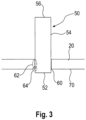
- Figure 3 shows a schematic representation of the connection of a bolt 50 to the smoothing blade 20.
- the bolt has a lower end 52, a bolt shaft 54, and a bolt head 56.
- a recess 60 is provided in the smoothing blade 20 for the bolt.
- this recess is expediently provided as a round hole.
- the recess can be created by drilling or punching.
- the lower bolt end 52 is pushed from the top of the smoothing blade 20 completely through the recess 60. Therefore, the lower bolt end 52 of the bolt 50 protrudes and projects beyond the working surface 70 of the smoothing blade 20.
- connection can then quickly become loose. Furthermore, the connection is usually no longer completely flat. In some cases, the bolt end either protrudes beyond the working side 70 of the smoothing blade 20 or retracts behind it. In one case, a protrusion is created, in the other, a hollow is formed. Both adversely affect the smoothing result to such an extent that the smoothing trowel usually has to be taken out of service.
- the bolt 50 is guided through the recess 60 in the smoothing blade to provide a welded joint.
- a welded joint can be provided in the first welding area 62.
- This welding area lies in the gap between the walls of the recess 60 and the outer circumference of the bolt 50, entirely or substantially between the top and working side of the smoothing blade 20.
- Welding can also be performed there, if necessary, using a filler metal.
- welding can be performed in the second welding area 64. This welding area lies in the exit area of the bolt. Welding therefore takes place directly on the working side 70 of the smoothing blade 20.
- a weld seam runs annularly along the edge of the recess and thus also forms a ring around the bolt.
- a round hole results in a round ring.
- Welding can be performed with the aid of a filler metal. Alternatively, welding can also be performed without filler metal. It may be useful to melt off part of the bolt material, particularly parts of the protruding bolt material, and use it to create a weld seam.
- the bolt shaft 54 is guided into corresponding holes or recesses in the handle holder, typically the handle shoe 42.
- the connection can be made by screwing. A thread would then be provided on the bolt shaft 54.
- the connection can also be made by pressing. In this case, sufficient pressure is exerted on the bolt from the direction of the bolt head 56 that it fills a correspondingly dimensioned recess in the handle holder.
- a softer bolt material should be provided, for example, aluminum.
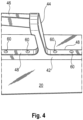
- FIG 4 shows, with an enlarged detail, how the connection between the smoothing blade 20 and the handle holder 40 can be established.
- a plurality of bolts 60 are connected to the smoothing blade 20.
- the bolts are connected to the smoothing blade 20 at regular or variable intervals.
- the bolts are then inserted into matching recesses in the handle holder 40, preferably in the handle shoe 42.
- Bolts are shown which have been pressed in. Accordingly, it is not necessary to have Nuts are provided. It is advisable to grind the upper surface 48 of the grip shoe 42 after pressing. This results in a flush finish of the bolts 60 with the upper surface 48 of the grip shoe 42, as shown.
Landscapes
- Engineering & Computer Science (AREA)
- Architecture (AREA)
- Mechanical Engineering (AREA)
- Civil Engineering (AREA)
- Structural Engineering (AREA)
- Conveying And Assembling Of Building Elements In Situ (AREA)
Claims (12)
- Truelle de lissage (10) qui comprend une lame de lissage (20) et une poignée (30) et dans laquelle un support de poignée (40) relie la poignée (30) à la lame de lissage (20), le support de poignée (40) étant relié à la lame de lissage (20) par une pluralité de boulons (50), des évidements (60) étant prévus dans la lame de lissage (20) et les boulons (50) étant introduits dans ces évidements (60), caractérisé en ce que le support de poignée (40) est relié par une pluralité de boulons (50) à la lame de lissage (20) par des liaisons soudées.
- Truelle de lissage (10) selon la revendication précédente, dans laquelle des joints soudés sont prévus sur le côté de travail de la lame de lissage.
- Truelle de lissage (10) selon l'une quelconque des revendications précédentes, dans laquelle des joints soudés sont prévus dans la zone des évidements.
- Truelle de lissage (10) selon l'une quelconque des revendications précédentes, dans laquelle les joints soudés sont réalisés par soudage au laser.
- Truelle de lissage (10) selon l'une quelconque des revendications précédentes, dans laquelle la lame de lissage (20) est fabriquée en acier au chrome-molybdène
- Truelle de lissage (10) selon l'une des revendications précédentes, dans laquelle les boulons (50) sont guidés dans des passages du support de poignée (40) et y sont comprimés.
- Truelle de lissage (10) selon l'une quelconque des revendications précédentes, dans laquelle tous les boulons (50) ont le même diamètre
- Procédé de fabrication d'une truelle de lissage (10), comprenant les étapes suivantes :a. Fournir une lame de lissage avec une face supérieure et une face de travailb. Fournir un support de poignée avec une pluralité de boulonsc. Création de évidements dans la feuille de lissaged. Introduction de la multitude de boulons dans les évidementse. Soudage de la multitude de boulons depuis le côté
- Procédé de fabrication d'une truelle de lissage (10) selon la revendication 6 ou 7, dans lequel le soudage du boulon est effectué par soudage au laser.
- Procédé de fabrication d'une truelle de lissage (10) selon l'une quelconque des revendications 8 à 9, dans lequel le boulon dépasse du côté de travail de la lame de lissage et le matériau du boulon est déplacé dans un espace entre le boulon et le trou dans le processus de soudage.
- Procédé de fabrication d'une truelle de lissage (10) selon la revendication précédente, dans lequel un dépassement de boulon est enlevé au-dessus du côté de travail de la lame de lissage.
- Procédé de fabrication d'une truelle de lissage (10) selon l'une quelconque des revendications 8 à 11, dans lequel la direction à partir de laquelle la soudure est effectuée est opposée à la direction à partir de laquelle les boulons sont amenés.
Applications Claiming Priority (2)
| Application Number | Priority Date | Filing Date | Title |
|---|---|---|---|
| EP21000163.2A EP4108852A1 (fr) | 2021-06-23 | 2021-06-23 | Taloche lisse longue duré de vie |
| PCT/EP2022/000058 WO2023274571A1 (fr) | 2021-06-23 | 2022-06-23 | Truelle à lisser durable |
Publications (2)
| Publication Number | Publication Date |
|---|---|
| EP4359623A1 EP4359623A1 (fr) | 2024-05-01 |
| EP4359623B1 true EP4359623B1 (fr) | 2025-04-23 |
Family
ID=76971597
Family Applications (2)
| Application Number | Title | Priority Date | Filing Date |
|---|---|---|---|
| EP21000163.2A Ceased EP4108852A1 (fr) | 2021-06-23 | 2021-06-23 | Taloche lisse longue duré de vie |
| EP22786286.9A Active EP4359623B1 (fr) | 2021-06-23 | 2022-06-23 | Truelle de lissage à longue durée de vie |
Family Applications Before (1)
| Application Number | Title | Priority Date | Filing Date |
|---|---|---|---|
| EP21000163.2A Ceased EP4108852A1 (fr) | 2021-06-23 | 2021-06-23 | Taloche lisse longue duré de vie |
Country Status (5)
| Country | Link |
|---|---|
| US (1) | US20240367307A1 (fr) |
| EP (2) | EP4108852A1 (fr) |
| CA (1) | CA3225318A1 (fr) |
| PL (1) | PL4359623T3 (fr) |
| WO (1) | WO2023274571A1 (fr) |
Family Cites Families (15)
| Publication number | Priority date | Publication date | Assignee | Title |
|---|---|---|---|---|
| DE1754183U (de) | 1957-08-21 | 1957-10-17 | Hallenscheid Geb | Glaettekelle. |
| GB1081582A (en) * | 1965-04-12 | 1967-08-31 | Brades Skelton & Tyzack Ltd | An improvement in or relating to plasterers trowels |
| DE1684410A1 (de) * | 1966-12-19 | 1969-10-30 | Wilhelm Rentrop | Maurerkelle mit einer Loetverbindung zwischen Kellenblatt und Handgriffstuetze |
| FR2281195A1 (fr) * | 1974-08-07 | 1976-03-05 | Beraud Ets M | Procede d'emmanchement des poignees de prehension des truelles, platroirs ou autres outils |
| DE2540885A1 (de) * | 1975-09-13 | 1977-03-24 | Guenter Gudd | Glaettspahn zum verputzen verschiebbar und mit auswechselbarem griff |
| DE2700739A1 (de) * | 1977-01-10 | 1978-07-13 | Schumacher Ii | Verteil- und glaettwerkzeug fuer maurer, verputzer und maler |
| US4467492A (en) * | 1983-04-04 | 1984-08-28 | Harrington Eugene M | Trowel type construction tool |
| SU1177380A1 (ru) * | 1984-03-22 | 1985-09-07 | Предприятие П/Я А-1950 | Инструментальна сталь |
| DE3639978A1 (de) | 1986-11-22 | 1988-06-01 | Happe Herbert Fa | Kelle, insbesondere zum mauern, fugen oder dergleichen |
| DE4140278A1 (de) * | 1991-12-06 | 1993-06-09 | Gustav Schumacher | Verteil- und glaettwerkzeug, insbesondere fuer maurer, verputzer und maler |
| US7331081B2 (en) * | 2004-04-01 | 2008-02-19 | Beno J. Gundlach Company | Trowel blade |
| US8151404B1 (en) * | 2005-01-26 | 2012-04-10 | Beno J. Gundlach Company | Modular trowel handle |
| US8434188B1 (en) | 2007-09-19 | 2013-05-07 | Exceptional Ip Holdings, Llc | Apparatus and methods for ergonomic building tools |
| DE102014002951A1 (de) * | 2014-03-06 | 2015-09-10 | Nela Gmbh | Vorrichtung zum Glätten |
| CN204983571U (zh) * | 2015-07-30 | 2016-01-20 | 唐亮 | 铸造抹泥刀连接板及其抹泥刀 |
-
2021
- 2021-06-23 EP EP21000163.2A patent/EP4108852A1/fr not_active Ceased
-
2022
- 2022-06-23 CA CA3225318A patent/CA3225318A1/fr active Pending
- 2022-06-23 EP EP22786286.9A patent/EP4359623B1/fr active Active
- 2022-06-23 PL PL22786286.9T patent/PL4359623T3/pl unknown
- 2022-06-23 US US18/574,012 patent/US20240367307A1/en active Pending
- 2022-06-23 WO PCT/EP2022/000058 patent/WO2023274571A1/fr not_active Ceased
Also Published As
| Publication number | Publication date |
|---|---|
| PL4359623T3 (pl) | 2025-08-25 |
| EP4359623A1 (fr) | 2024-05-01 |
| CA3225318A1 (fr) | 2023-01-05 |
| WO2023274571A1 (fr) | 2023-01-05 |
| US20240367307A1 (en) | 2024-11-07 |
| EP4108852A1 (fr) | 2022-12-28 |
Similar Documents
| Publication | Publication Date | Title |
|---|---|---|
| DE3420263C2 (fr) | ||
| DE3106313A1 (de) | Einrichtung und verfahren zum verbinden von blechen | |
| DE2933492A1 (de) | Gelaender, gitter o.dgl. und verfahren zur herstellung desselben | |
| DE1500759B1 (de) | Stahlstabverbindung,insbesondere fuer Staebe von armierten Betonteilen | |
| WO2008125326A2 (fr) | Dispositif de séparation d'un assemblage de tiges en matière plastique à l'aide d'un dispositif à entaille et d'un support portant un dispositif de découpe | |
| DE2720924A1 (de) | Lappenverbindung zum festen gegenseitigen verbinden von plattenstuecken und verfahren zur herstellung einer solchen lappenverbindung | |
| EP2395253A2 (fr) | Élément de corps creux et composant assemblé | |
| EP3269509B1 (fr) | Pince pour réaliser de troux sur des profiles à section trapézoïdale | |
| EP2789406B2 (fr) | Cintreuse | |
| DE1679124A1 (de) | Verfahren und Vorrichtung zur Herstellung einer widerstandsfaehigen Leiterverbindung | |
| EP4359623B1 (fr) | Truelle de lissage à longue durée de vie | |
| DE1684191C3 (de) | Gerüstrohrkupplung zum Verbin den zweier rechtwinklig sich kreuzen der Gerustrohre und Verfahren zur Her stellung von Sattelstucken fur eine derartige Gerüstrohrkupplung | |
| DE3101995C2 (fr) | ||
| DE102005052282A1 (de) | Sperr-Rad für einen Anbind-Apparat | |
| EP4050171B1 (fr) | Structure de support et son procédé de fabrication | |
| DE1926975B2 (de) | Vorrichtung zum Befestigen eines Kletterschalungselementes | |
| EP0531879B1 (fr) | Lame de scie à ruban et procédé pour sa fabrication | |
| DE2733252B2 (de) | Verfahren und Vorrichtung zum Herstellen eines Gitterträgers | |
| DE2066024C3 (de) | Biegewerkzeug zum Herstellen von Plattengliedern für Plattenbandförderer | |
| DE102012008748B4 (de) | Kettenlaschenpositionierhilfe, Kettentrenn- und -vernietwerkzeug sowie Verfahren zum Positionieren von Laschen und Bolzen einer Bolzen-Laschen-Kette | |
| DE60221393T2 (de) | Verfahren zur Herstellung eines vertikalen Gerüstelementes, und durch Anwendung dieses Verfahrens hergestelltes Element | |
| DE102022125475B4 (de) | Wasserstrahlschneideverfahren | |
| DE2344831A1 (de) | Verfahren zur herstellung von krummlinigen fittings und einrichtung zur durchfuehrung des verfahrens | |
| DE202007018107U1 (de) | Vorrichtung zum Öffnen von Nuten | |
| DE2823799C3 (de) | Verfahren zum Schmieden von Kurbelkröpfungen |
Legal Events
| Date | Code | Title | Description |
|---|---|---|---|
| STAA | Information on the status of an ep patent application or granted ep patent |
Free format text: STATUS: UNKNOWN |
|
| STAA | Information on the status of an ep patent application or granted ep patent |
Free format text: STATUS: THE INTERNATIONAL PUBLICATION HAS BEEN MADE |
|
| PUAI | Public reference made under article 153(3) epc to a published international application that has entered the european phase |
Free format text: ORIGINAL CODE: 0009012 |
|
| STAA | Information on the status of an ep patent application or granted ep patent |
Free format text: STATUS: REQUEST FOR EXAMINATION WAS MADE |
|
| 17P | Request for examination filed |
Effective date: 20240122 |
|
| AK | Designated contracting states |
Kind code of ref document: A1 Designated state(s): AL AT BE BG CH CY CZ DE DK EE ES FI FR GB GR HR HU IE IS IT LI LT LU LV MC MK MT NL NO PL PT RO RS SE SI SK SM TR |
|
| DAV | Request for validation of the european patent (deleted) | ||
| DAX | Request for extension of the european patent (deleted) | ||
| GRAP | Despatch of communication of intention to grant a patent |
Free format text: ORIGINAL CODE: EPIDOSNIGR1 |
|
| STAA | Information on the status of an ep patent application or granted ep patent |
Free format text: STATUS: GRANT OF PATENT IS INTENDED |
|
| INTG | Intention to grant announced |
Effective date: 20241121 |
|
| GRAS | Grant fee paid |
Free format text: ORIGINAL CODE: EPIDOSNIGR3 |
|
| GRAA | (expected) grant |
Free format text: ORIGINAL CODE: 0009210 |
|
| STAA | Information on the status of an ep patent application or granted ep patent |
Free format text: STATUS: THE PATENT HAS BEEN GRANTED |
|
| AK | Designated contracting states |
Kind code of ref document: B1 Designated state(s): AL AT BE BG CH CY CZ DE DK EE ES FI FR GB GR HR HU IE IS IT LI LT LU LV MC MK MT NL NO PL PT RO RS SE SI SK SM TR |
|
| REG | Reference to a national code |
Ref country code: GB Ref legal event code: FG4D Free format text: NOT ENGLISH |
|
| REG | Reference to a national code |
Ref country code: CH Ref legal event code: EP |
|
| REG | Reference to a national code |
Ref country code: DE Ref legal event code: R096 Ref document number: 502022003704 Country of ref document: DE |
|
| REG | Reference to a national code |
Ref country code: IE Ref legal event code: FG4D Free format text: LANGUAGE OF EP DOCUMENT: GERMAN |
|
| PGFP | Annual fee paid to national office [announced via postgrant information from national office to epo] |
Ref country code: DE Payment date: 20250630 Year of fee payment: 4 |
|
| PGFP | Annual fee paid to national office [announced via postgrant information from national office to epo] |
Ref country code: AT Payment date: 20250721 Year of fee payment: 4 |
|
| REG | Reference to a national code |
Ref country code: NL Ref legal event code: MP Effective date: 20250423 |
|
| P01 | Opt-out of the competence of the unified patent court (upc) registered |
Free format text: CASE NUMBER: UPC_APP_2064_4359623/2025 Effective date: 20250731 |
|
| PG25 | Lapsed in a contracting state [announced via postgrant information from national office to epo] |
Ref country code: NL Free format text: LAPSE BECAUSE OF FAILURE TO SUBMIT A TRANSLATION OF THE DESCRIPTION OR TO PAY THE FEE WITHIN THE PRESCRIBED TIME-LIMIT Effective date: 20250423 |
|
| PG25 | Lapsed in a contracting state [announced via postgrant information from national office to epo] |
Ref country code: PT Free format text: LAPSE BECAUSE OF FAILURE TO SUBMIT A TRANSLATION OF THE DESCRIPTION OR TO PAY THE FEE WITHIN THE PRESCRIBED TIME-LIMIT Effective date: 20250825 Ref country code: ES Free format text: LAPSE BECAUSE OF FAILURE TO SUBMIT A TRANSLATION OF THE DESCRIPTION OR TO PAY THE FEE WITHIN THE PRESCRIBED TIME-LIMIT Effective date: 20250423 Ref country code: FI Free format text: LAPSE BECAUSE OF FAILURE TO SUBMIT A TRANSLATION OF THE DESCRIPTION OR TO PAY THE FEE WITHIN THE PRESCRIBED TIME-LIMIT Effective date: 20250423 |
|
| REG | Reference to a national code |
Ref country code: LT Ref legal event code: MG9D |
|
| PG25 | Lapsed in a contracting state [announced via postgrant information from national office to epo] |
Ref country code: NO Free format text: LAPSE BECAUSE OF FAILURE TO SUBMIT A TRANSLATION OF THE DESCRIPTION OR TO PAY THE FEE WITHIN THE PRESCRIBED TIME-LIMIT Effective date: 20250723 Ref country code: GR Free format text: LAPSE BECAUSE OF FAILURE TO SUBMIT A TRANSLATION OF THE DESCRIPTION OR TO PAY THE FEE WITHIN THE PRESCRIBED TIME-LIMIT Effective date: 20250724 |
|
| PGFP | Annual fee paid to national office [announced via postgrant information from national office to epo] |
Ref country code: PL Payment date: 20250709 Year of fee payment: 4 |
|
| PG25 | Lapsed in a contracting state [announced via postgrant information from national office to epo] |
Ref country code: BG Free format text: LAPSE BECAUSE OF FAILURE TO SUBMIT A TRANSLATION OF THE DESCRIPTION OR TO PAY THE FEE WITHIN THE PRESCRIBED TIME-LIMIT Effective date: 20250423 |
|
| PG25 | Lapsed in a contracting state [announced via postgrant information from national office to epo] |
Ref country code: HR Free format text: LAPSE BECAUSE OF FAILURE TO SUBMIT A TRANSLATION OF THE DESCRIPTION OR TO PAY THE FEE WITHIN THE PRESCRIBED TIME-LIMIT Effective date: 20250423 |
|
| PGFP | Annual fee paid to national office [announced via postgrant information from national office to epo] |
Ref country code: FR Payment date: 20250718 Year of fee payment: 4 |
|
| PG25 | Lapsed in a contracting state [announced via postgrant information from national office to epo] |
Ref country code: RS Free format text: LAPSE BECAUSE OF FAILURE TO SUBMIT A TRANSLATION OF THE DESCRIPTION OR TO PAY THE FEE WITHIN THE PRESCRIBED TIME-LIMIT Effective date: 20250723 |
|
| PG25 | Lapsed in a contracting state [announced via postgrant information from national office to epo] |
Ref country code: IS Free format text: LAPSE BECAUSE OF FAILURE TO SUBMIT A TRANSLATION OF THE DESCRIPTION OR TO PAY THE FEE WITHIN THE PRESCRIBED TIME-LIMIT Effective date: 20250823 |
|
| PG25 | Lapsed in a contracting state [announced via postgrant information from national office to epo] |
Ref country code: LV Free format text: LAPSE BECAUSE OF FAILURE TO SUBMIT A TRANSLATION OF THE DESCRIPTION OR TO PAY THE FEE WITHIN THE PRESCRIBED TIME-LIMIT Effective date: 20250423 |
|
| PG25 | Lapsed in a contracting state [announced via postgrant information from national office to epo] |
Ref country code: DK Free format text: LAPSE BECAUSE OF FAILURE TO SUBMIT A TRANSLATION OF THE DESCRIPTION OR TO PAY THE FEE WITHIN THE PRESCRIBED TIME-LIMIT Effective date: 20250423 Ref country code: SM Free format text: LAPSE BECAUSE OF FAILURE TO SUBMIT A TRANSLATION OF THE DESCRIPTION OR TO PAY THE FEE WITHIN THE PRESCRIBED TIME-LIMIT Effective date: 20250423 |
|
| PG25 | Lapsed in a contracting state [announced via postgrant information from national office to epo] |
Ref country code: CZ Free format text: LAPSE BECAUSE OF FAILURE TO SUBMIT A TRANSLATION OF THE DESCRIPTION OR TO PAY THE FEE WITHIN THE PRESCRIBED TIME-LIMIT Effective date: 20250423 |
|
| PG25 | Lapsed in a contracting state [announced via postgrant information from national office to epo] |
Ref country code: EE Free format text: LAPSE BECAUSE OF FAILURE TO SUBMIT A TRANSLATION OF THE DESCRIPTION OR TO PAY THE FEE WITHIN THE PRESCRIBED TIME-LIMIT Effective date: 20250423 |
|
| REG | Reference to a national code |
Ref country code: DE Ref legal event code: R097 Ref document number: 502022003704 Country of ref document: DE |
|
| PG25 | Lapsed in a contracting state [announced via postgrant information from national office to epo] |
Ref country code: SK Free format text: LAPSE BECAUSE OF FAILURE TO SUBMIT A TRANSLATION OF THE DESCRIPTION OR TO PAY THE FEE WITHIN THE PRESCRIBED TIME-LIMIT Effective date: 20250423 |
|
| REG | Reference to a national code |
Ref country code: CH Ref legal event code: H13 Free format text: ST27 STATUS EVENT CODE: U-0-0-H10-H13 (AS PROVIDED BY THE NATIONAL OFFICE) Effective date: 20260127 |
|
| PG25 | Lapsed in a contracting state [announced via postgrant information from national office to epo] |
Ref country code: IT Free format text: LAPSE BECAUSE OF FAILURE TO SUBMIT A TRANSLATION OF THE DESCRIPTION OR TO PAY THE FEE WITHIN THE PRESCRIBED TIME-LIMIT Effective date: 20250423 |
|
| PG25 | Lapsed in a contracting state [announced via postgrant information from national office to epo] |
Ref country code: MC Free format text: LAPSE BECAUSE OF FAILURE TO SUBMIT A TRANSLATION OF THE DESCRIPTION OR TO PAY THE FEE WITHIN THE PRESCRIBED TIME-LIMIT Effective date: 20250423 |
|
| PG25 | Lapsed in a contracting state [announced via postgrant information from national office to epo] |
Ref country code: LU Free format text: LAPSE BECAUSE OF NON-PAYMENT OF DUE FEES Effective date: 20250623 |
|
| REG | Reference to a national code |
Ref country code: BE Ref legal event code: MM Effective date: 20250630 |
|
| PLBE | No opposition filed within time limit |
Free format text: ORIGINAL CODE: 0009261 |
|
| STAA | Information on the status of an ep patent application or granted ep patent |
Free format text: STATUS: NO OPPOSITION FILED WITHIN TIME LIMIT |
|
| REG | Reference to a national code |
Ref country code: CH Ref legal event code: L10 Free format text: ST27 STATUS EVENT CODE: U-0-0-L10-L00 (AS PROVIDED BY THE NATIONAL OFFICE) Effective date: 20260304 |
|
| PG25 | Lapsed in a contracting state [announced via postgrant information from national office to epo] |
Ref country code: RO Free format text: LAPSE BECAUSE OF FAILURE TO SUBMIT A TRANSLATION OF THE DESCRIPTION OR TO PAY THE FEE WITHIN THE PRESCRIBED TIME-LIMIT Effective date: 20250423 |
|
| 26N | No opposition filed |
Effective date: 20260126 |
|
| PG25 | Lapsed in a contracting state [announced via postgrant information from national office to epo] |
Ref country code: IE Free format text: LAPSE BECAUSE OF NON-PAYMENT OF DUE FEES Effective date: 20250623 |
|
| PG25 | Lapsed in a contracting state [announced via postgrant information from national office to epo] |
Ref country code: BE Free format text: LAPSE BECAUSE OF NON-PAYMENT OF DUE FEES Effective date: 20250630 |
|
| PG25 | Lapsed in a contracting state [announced via postgrant information from national office to epo] |
Ref country code: CH Free format text: LAPSE BECAUSE OF NON-PAYMENT OF DUE FEES Effective date: 20250630 |