EP4359623B1 - Langlebige glättekelle - Google Patents
Langlebige glättekelle Download PDFInfo
- Publication number
- EP4359623B1 EP4359623B1 EP22786286.9A EP22786286A EP4359623B1 EP 4359623 B1 EP4359623 B1 EP 4359623B1 EP 22786286 A EP22786286 A EP 22786286A EP 4359623 B1 EP4359623 B1 EP 4359623B1
- Authority
- EP
- European Patent Office
- Prior art keywords
- smoothing
- trowel
- blade
- handle
- bolts
- Prior art date
- Legal status (The legal status is an assumption and is not a legal conclusion. Google has not performed a legal analysis and makes no representation as to the accuracy of the status listed.)
- Active
Links
Images


Classifications
-
- B—PERFORMING OPERATIONS; TRANSPORTING
- B25—HAND TOOLS; PORTABLE POWER-DRIVEN TOOLS; MANIPULATORS
- B25G—HANDLES FOR HAND IMPLEMENTS
- B25G3/00—Attaching handles to the implements
- B25G3/34—Attaching handles to the implements by pressing the handle on the implements; using cement or molten metal, e.g. casting, moulding, by welding or the like
-
- E—FIXED CONSTRUCTIONS
- E04—BUILDING
- E04F—FINISHING WORK ON BUILDINGS, e.g. STAIRS, FLOORS
- E04F21/00—Implements for finishing work on buildings
- E04F21/02—Implements for finishing work on buildings for applying plasticised masses to surfaces, e.g. plastering walls
- E04F21/16—Implements for after-treatment of plaster or the like before it has hardened or dried, e.g. smoothing-tools, profile trowels
- E04F21/161—Trowels
-
- E—FIXED CONSTRUCTIONS
- E04—BUILDING
- E04F—FINISHING WORK ON BUILDINGS, e.g. STAIRS, FLOORS
- E04F21/00—Implements for finishing work on buildings
- E04F21/20—Implements for finishing work on buildings for laying flooring
- E04F21/24—Implements for finishing work on buildings for laying flooring of masses made in situ, e.g. smoothing tools
- E04F21/241—Elongated smoothing blades or plates, e.g. screed apparatus
-
- E—FIXED CONSTRUCTIONS
- E04—BUILDING
- E04G—SCAFFOLDING; FORMS; SHUTTERING; BUILDING IMPLEMENTS OR AIDS, OR THEIR USE; HANDLING BUILDING MATERIALS ON THE SITE; REPAIRING, BREAKING-UP OR OTHER WORK ON EXISTING BUILDINGS
- E04G21/00—Preparing, conveying, or working-up building materials or building elements in situ; Other devices or measures for constructional work
- E04G21/14—Conveying or assembling building elements
- E04G21/16—Tools or apparatus
- E04G21/20—Tools or apparatus for applying mortar
- E04G21/201—Trowels
Definitions
- the present invention relates to a tool that can be used for spreading and smoothing building materials, particularly plaster and mortar. It is typically used for plastering.
- the tool is generally referred to here as a smoothing trowel.
- the invention equally relates to spatulas, in particular also surface spatulas, painter's spatulas, and plaster filler knives, as well as, in individual cases, squeegees.
- the invention also relates to corner trowels, inside corner trowels and outside corner trowels, mortar trowels, and point trowels, each in toothed and untoothed versions.
- the utility model DE 1 754 183 discloses a smoothing trowel whose main elements are the blade, a handle support, and the handle.
- the handle support is attached to a bar that stabilizes the blade.
- it can be advantageous to manufacture all three parts in one piece from plastic. This also avoids the difficulty of creating a reliable connection, as the mechanical stress on the trowels and contact with mortar can weaken connections over time.
- the disclosure document DE 1 684 410 discloses a bricklayer's trowel with a soldered joint between the blade and the handle support.
- the soldered joint is intended to improve the strength of the connection between the handle and the blade.
- the solder is introduced into holes in the sole plate of the handle, which are additionally provided with extensions at the end facing the blade. This solution may have proven successful for various trowels. However, it seems desirable to to have more freedom in the design and choice of materials for the handle support and trowel blade, and to be able to offer alternatives to the solder connection.
- the disclosure document DE 25 40 885 discloses a smoothing trowel or "smoothing chip" for plastering with a movable and replaceable handle.
- a guide rail is provided on the smoothing blade, to which the handle is attached.
- the guide rail is welded to the steel smoothing blade.
- the patent application DE 3639978 discloses a bricklayer's trowel in which the handle is positioned behind the blade and connected to the blade by a curved piece of tubing, the so-called tang.
- the attachment between the tang and the blade is to be achieved by welding.
- This design may produce a very durable connection, but it is not very suitable for other trowel shapes, such as those in which the handle is located above the center of the blade.
- the US Patent 9,784,000 discloses that bolts can be welded onto the top of the trowel blade and a handle can be attached via these bolts.
- US2005034262A1 discloses a smoothing trowel according to the preamble of claim 1 and a method according to steps a. to e. of claim 8.
- the invention aims to overcome the disadvantages of the prior art. It aims to provide a durable and robust smoothing trowel that can also be produced efficiently.
- smoothing trowel is also to be understood as a term used to describe related tools used for spreading building materials, especially those exemplified above with typical names.
- a smoothing trowel comprises at least one smoothing blade and a handle.
- the smoothing blade is usually a completely or predominantly flat surface, allowing it to be used for smoothing on a single level across the entire surface. Exceptions are corner trowels for internal or external corners/edges, where the smoothing blade is curved so that the two main working surfaces are at a 90° angle to each other.
- a handle holder connects the handle to the smoothing blade.
- the handle holder can be a separate component, or alternatively, it could be made integrally with the handle or the smoothing blade.
- the handle holder can be conveniently made of a metal, such as steel, stainless steel, or aluminum. It is particularly suitable to manufacture the handle holder as a cast component, preferably as a die-cast aluminum component.
- the handle holder could also be made of plastic, even using an injection molding process.
- the handle holder should be connected to the smoothing blade with a plurality of bolts.
- “Plurality” here means at least two bolts, but between four and ten bolts are often used.
- the bolts are preferably made of metal, such as steel, stainless steel, or aluminum. A metal that is easy to weld is advantageous. It is also possible to weld the bolts to the handle holder. It may also be advantageous to screw the bolts. It may be advisable to select the bolt material so that a press fit can be achieved.
- Trowels are available in which the first and last bolts in a connecting row are thicker than the other bolts. Since the first and last bolts are subject to greater stress than the other bolts, this can offer advantages. However, the present invention allows for a secure and permanent connection without requiring the first and last bolts to be thicker.
- recesses are to be provided in the smoothing blade.
- These recesses can be round holes, for example.
- the bolts are inserted into these recesses. This means that the bolts are not meant to rest on the smoothing blade, but are at least partially guided through it.
- This type of connection geometry unlike conventional bolted connections, results in a stronger and more durable bond.
- a smoothing trowel is often used for several years, sometimes even for more than a decade. It is exposed to high mechanical stress, particularly because at least the smoothing blade typically has a certain degree of elasticity. It is also exposed to chemical stress, particularly when in contact with alkaline mortar or plaster.
- the bolts are welded to the screed blade.
- Laser welding also known as laser beam welding, is particularly suitable for connecting the bolts to the smoothing plate. It can be used as heat conduction welding or deep penetration welding. In individual cases, it can be combined with other welding, joining, or connection techniques. Preferably, the connection is made solely by laser welding. Preferably, no filler metal is used.
- Chromium-molybdenum steel is also used here as a generic term for alloys that contain other (smaller) components; it is particularly advantageous if the alloy contains nickel.
- the handle holder prefferably has a grip shoe, a handle shaft, and a handle core. These can be designed as separate components, or the handle holder can be a single piece.
- the connection to the smoothing blade is made via the grip shoe.
- the grip shoe can, for example, be cuboid-shaped and be aligned with the handle shaft on its have a flat surface on the opposite side for contact and connection with the smoothing blade.
- the handle shaft serves as the connection between the grip shoe and the handle core. It runs essentially perpendicular to the contact surface of the grip shoe, i.e., when mounted, it is essentially perpendicular to the smoothing blade.
- the handle core typically runs essentially parallel to the smoothing blade.
- the handle core is surrounded by a grip.
- the grip can be ergonomically designed. It is often made of plastic, but can also be made of cork, for example.
- the grip can be made in one piece with the handle core, but a removable and, if necessary, replaceable grip is advantageous. The grip can then be attached to the handle core and connected to it, for example, by wedges, glue, or even screws.
- the bolts are connected to the handle holder by pressing.
- the bolts are inserted into recesses in the handle holder (provided the handle holder has a grip shoe).
- the bolts are then compressed under high pressure so that they completely fill the recesses, usually round holes, in the handle shoe.
- a bolt cap can also be created that protrudes beyond the holes in the handle shoe and has a thickened portion at the top, creating an additional (positive-locking) connection with the handle shoe.
- the invention also relates to a method for producing a smoothing trowel according to the appended claim 8.
- the holder can stabilize the bolts in the correct position for welding. After welding, the holder can be removed.
- a variety of devices can be used as a holder.
- a mechanical holder can also be provided as a holder, which provides appropriate temporary support for the bolts, for example, by supporting them from the top side of the screed blade. (The top side is the side opposite the working side.)
- the handle holder itself can serve as a holder during this process step.
- the bolts are welded from the direction of the working side of the smoothing blade. It is fundamentally advantageous for processes for producing smoothing blades if the feed direction of the studs and the direction from which welding is carried out are opposite each other.
- the first direction feed direction
- the second direction welding machine approach direction
- both hemispheres arranged opposite each other around a central axis.
- first direction can lie in a first right circular cone and the second direction (welding machine approach direction) can lie in a second right circular cone, with both circular cones arranged opposite each other around a central axis, so that they form a double cone.
- Both circular cones can have a central angle of 90° or less.
- the studs protrude a certain distance above the screed blade. However, this distance is usually much shorter than the stud length. Therefore, if a large number of studs are used, especially more than four, and the studs are spaced closer than 5 cm apart, and especially closer than 3 cm or 2 cm apart, welding studs from the work side is easier. On the upper side of the screed blade, the protruding studs would obstruct the free approach and movement of a welding machine or torch.
- the handle holder is first equipped with bolts and the bolts are then provided together with the handle holder.
- the handle holder In a subsequent process step, the handle holder, along with the studs, would then have to be transported to the welding station. However, by appropriately preparing the handle holder, the welding process itself can be completed more quickly. This is particularly advantageous when the welding equipment used is expensive and a high throughput at the welding station is advantageous.
- the bolts are welded by laser welding.
- the studs used protrude beyond the working side of the screed blade and stud material is removed there during the welding process.
- material can be melted. In this process, all or only part of the material protruding beyond the working side can be moved. In this way, the hole, which must be at least slightly larger than the stud circumference, is completely or partially closed. The movement of material can be made easier by the effect of gravity if the studs are oriented accordingly. It is therefore advisable for the stud ends to point upwards.
- the sealing could be achieved using a welding filler, such as a welding wire, but in the context of the present invention, welding without a welding filler is preferred.
- the welding process without a welding filler is even more economical and faster.
- a bolt protrusion is not advantageous per se, and this process concept is therefore not intuitive. Nevertheless, it has proven advantageous within the scope of the present invention to accept the occurrence of a bolt protrusion in the corresponding process step.
- Figure 1 shows a smoothing trowel according to the invention in perspective view.
- the smoothing trowel 10 has a smoothing blade 20, which is guided by the handle 30.
- the handle holder 40 serves to connect the handle 30 and the smoothing blade 20.
- the handle holder 40 is connected to the smoothing blade 20 by a plurality of bolts 50.
- FIG 2 shows, in the same perspective view, a smoothing trowel 10 according to the invention, but with the handle 30 removed.
- the handle holder 40 comprises the grip shoe 42.
- the grip shoe rests directly on the upper side of the smoothing blade 20. (Indirect resting via an intermediate layer is also conceivable.) It extends over a substantial part of the length of the smoothing blade, expediently generally over more than 50% of the length, typically between 50 and 80% of the length of the smoothing blade.
- the grip shoe 42 is connected to a handle shaft 44 projecting from the handle shoe 42.
- the handle shaft 44 establishes the connection to the handle core 46.
- the handle core 46 is expediently a rod or tube section.
- the handle core 46 can have a profile, for example, a square or rectangular profile, that prevents the handle from twisting around the longitudinal axis of the handle core 46. A square profile is shown here.
- a thread can also be provided at the end of the handle core, for example, through which the handle 30 can be secured with a nut to prevent it from slipping off the handle core 46.
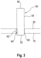
- Figure 3 shows a schematic representation of the connection of a bolt 50 to the smoothing blade 20.
- the bolt has a lower end 52, a bolt shaft 54, and a bolt head 56.
- a recess 60 is provided in the smoothing blade 20 for the bolt.
- this recess is expediently provided as a round hole.
- the recess can be created by drilling or punching.
- the lower bolt end 52 is pushed from the top of the smoothing blade 20 completely through the recess 60. Therefore, the lower bolt end 52 of the bolt 50 protrudes and projects beyond the working surface 70 of the smoothing blade 20.
- connection can then quickly become loose. Furthermore, the connection is usually no longer completely flat. In some cases, the bolt end either protrudes beyond the working side 70 of the smoothing blade 20 or retracts behind it. In one case, a protrusion is created, in the other, a hollow is formed. Both adversely affect the smoothing result to such an extent that the smoothing trowel usually has to be taken out of service.
- the bolt 50 is guided through the recess 60 in the smoothing blade to provide a welded joint.
- a welded joint can be provided in the first welding area 62.
- This welding area lies in the gap between the walls of the recess 60 and the outer circumference of the bolt 50, entirely or substantially between the top and working side of the smoothing blade 20.
- Welding can also be performed there, if necessary, using a filler metal.
- welding can be performed in the second welding area 64. This welding area lies in the exit area of the bolt. Welding therefore takes place directly on the working side 70 of the smoothing blade 20.
- a weld seam runs annularly along the edge of the recess and thus also forms a ring around the bolt.
- a round hole results in a round ring.
- Welding can be performed with the aid of a filler metal. Alternatively, welding can also be performed without filler metal. It may be useful to melt off part of the bolt material, particularly parts of the protruding bolt material, and use it to create a weld seam.
- the bolt shaft 54 is guided into corresponding holes or recesses in the handle holder, typically the handle shoe 42.
- the connection can be made by screwing. A thread would then be provided on the bolt shaft 54.
- the connection can also be made by pressing. In this case, sufficient pressure is exerted on the bolt from the direction of the bolt head 56 that it fills a correspondingly dimensioned recess in the handle holder.
- a softer bolt material should be provided, for example, aluminum.
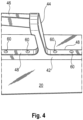
- FIG 4 shows, with an enlarged detail, how the connection between the smoothing blade 20 and the handle holder 40 can be established.
- a plurality of bolts 60 are connected to the smoothing blade 20.
- the bolts are connected to the smoothing blade 20 at regular or variable intervals.
- the bolts are then inserted into matching recesses in the handle holder 40, preferably in the handle shoe 42.
- Bolts are shown which have been pressed in. Accordingly, it is not necessary to have Nuts are provided. It is advisable to grind the upper surface 48 of the grip shoe 42 after pressing. This results in a flush finish of the bolts 60 with the upper surface 48 of the grip shoe 42, as shown.
Landscapes
- Engineering & Computer Science (AREA)
- Architecture (AREA)
- Mechanical Engineering (AREA)
- Civil Engineering (AREA)
- Structural Engineering (AREA)
- Conveying And Assembling Of Building Elements In Situ (AREA)
Description
- Die vorliegende Erfindung betrifft ein Werkzeug, das zum Verteilen und Glätten von Baumaterialien verwendet werden kann, besonders von Gips und Mörtel. Es wird typischerweise zum Verputzen eingesetzt. Das Werkzeug wird hier allgemein als Glättkelle bezeichnet. Die Erfindung bezieht sich aber gleichermaßen auf Spachtel, insbesondere auch Flächenspachtel, Malerspachtel und Gipsspachtel, wie auch im Einzelfall Rakel. Die Erfindung bezieht sich auch auf Eckenkellen, Inneneckenkellen wie Außeneckenkellen, Mörtelkellen und Spitzkellen, jeweils in gezahnter und ungezahnter Ausführung.
- Das Gebrauchsmuster
DE 1 754 183 offenbart eine Glättekelle, deren Hauptelemente das Kellenblatt, eine Griffstütze und der Griff sind. Die Griffstütze setzt an einer Leiste an, welche das Kellenblatt stabilisiert. Wie das Gebrauchsmuster offenbart, kann es vorteilhaft sein, alle drei Teile in einem Stück aus Kunststoff zu fertigen. Dies umgeht auch die Schwierigkeit einer zuverlässigen Verbindung, da die mechanische Belastung der Kellen und der Kontakt mit Mörtel Verbindungen über die Zeit schwächen können. - Die Offenlegungsschrift
DE 1 684 410 offenbart eine Maurerkelle mit einer Lötverbindung zwischen Kellenblatt und Handgriffstütze. Die Lötverbindung soll zu einer verbesserten Festigkeit bei der Verbindung zwischen Handgriff und Kellenblatt führen. Das Lot wird dazu in Bohrungen der Sohlenplatte des Griffes eingebracht, welche zusätzlich an dem Ende, welches dem Kellenblatt zugewandt ist, mit Erweiterungen versehen sind. Die Lösung mag sich für verschiedene Kellen bewährt haben. Es erscheint aber wünschenswert, jedenfalls um mehr Freiheit bei der Gestaltung und Materialwahl für Griffstütze und Kellenblatt zu haben, auch Alternativen zur Lotverbindung anbieten zu können. - Die Offenlegungsschrift
DE 25 40 885 offenbart eine Glättekelle oder einen "Glättspan" zum Verputzen mit verschiebbarem und auswechselbarem Griff. Dazu ist auf dem Glättblatt eine Führungsschiene vorgesehen, an der der Handgriff befestigt ist. Die Führungsschiene wird an dem aus Stahl bestehenden Glättblatt durch Schweißen aufgeheftet. - Die Patenschrift
DE 3639978 offenbart eine Maurerkelle, bei der der Griff hinter dem Kellenblatt angeordnet ist und mit einem geschwungenen Rohrstück, der sogenannten Angel, mit dem Kellenblatt verbunden wird. Die Befestigung zwischen Angel und Kellenblatt soll mittels Schweißung erfolgen. Diese Konstruktion mag eine sehr haltbare Verbindung erzeugen, ist jedoch für andere Kellenformen, beispielsweise solche, bei denen der Handgriff über der Blattmitte liegt, wenig geeignet. - Das
US-Patent 9 784 000 -
US2005034262A1 offenbart eine Glättkelle gemäß der Präambel des Anspruchs 1 und ein Verfahren gemäß den Schritten a. bis e. des Anspruchs 8. - Die Erfindung möchte die Nachteile im Stand der Technik umgehen. Es soll eine lange haltbare und robuste Glättekelle zur Verfügung gestellt werden. Diese soll auch effizient produziert werden können.
- Diese Aufgabe wird durch eine Glättkelle nach Anspruch 1 gelöst.
- Vorteilhafte Weiterbildungen sind in den Unteransprüchen angegeben. Diese und weitere Vorteile lassen sich im Übrigen mit einem Verfahren nach den Ansprüchen 8 bis 14 erreichen.
- "Glättkelle" ist im Rahmen dieser Erfindung auch als Begriff zur Bezeichnung verwandter Werkzeuge zu verstehen, die dem Verteilen von Baumaterial dienen, insbesondere solchen, die eingangs mit typischen Bezeichnungen exemplarisch benannt sind. Eine Glättkelle umfasst dabei zumindest ein Glättblatt und einen Handgriff. Das Glättblatt ist in der Regel eine ganz oder überwiegend ebene Fläche, sodass es über die ganze Fläche zum Glätten auf einer Ebene eingesetzt werden kann. Ausnahmen sind Eckkellen für innere oder für äußere Ecken/Kanten, bei denen das Glättblatt gebogen ist, sodass die beiden Hauptarbeitsflächen in einem 90° Winkel zueinander stehen.
- Ein Griffhalter soll den Handgriff mit dem Glättblatt verbinden. Der Griffhalter kann dabei ein separates Bauteil sein, alternativ könnte er einstückig mit dem Handgriff oder mit dem Glättblatt ausgeführt sein. Der Griffhalter kann zweckmäßigerweise aus einem Metall hergestellt werden, beispielsweise aus Stahl, Edelstahl oder Aluminium. Besonders bietet sich hier an, den Griffhalter als Gussbauteil zu fertigen, vorzugsweise als Aluminiumdruckguss-Bauteil. Der Griffhalter könnte auch aus Kunststoff hergestellt werden, durchaus auch im Spitzgussverfahren.
- Der Griffhalter soll mit einer Vielzahl von Bolzen mit dem Glättblatt verbunden sein. Unter einer Vielzahl ist hier mindestens zwei Bolzen zu verstehen, häufig zwischen 4 und 10 Bolzen verwendet. Vorteilhafterweise sind die Bolzen aus Metall, beispielsweise aus Stahl, Edelstahl oder Aluminium. Ein gut verschweißbares Metall ist von Vorteil. Es ist möglich die Bolzen auch mit dem Griffhalter zu verschweißen. Es kann auch vorteilhaft sein, dass die Bolzen verschraubt werden. Es kann zweckmäßig sein, das Bolzenmaterial so zu wählen, dass eine Pressverbindung zustande kommen kann.
- Es ist vorteilhaft, wenn die Mehrzahl der Bolzen oder auch alle Bolzen denselben Durchmesser haben. Dies sorgt für ein ansprechendes Erscheinungsbild der Kelle und vereinfacht die Herstellung. Es sind Kellen erhältlich, bei denen der erste und letzte Bolzen einer verbindenden Bolzenreihe dicker sind als die übrigen Bolzen. Da der erste und letzte Bolzen stärker belastet werden als die übrigen Bolzen, kann dies Vorteile bieten. Die vorliegende Erfindung erlaubt aber eine sichere und dauerhafter Verbindung, ohne dass der erste und der letzte Bolzen dicker gewählt werden müssten.
- Erfindungsgemäß sollen im Glättblatt Ausnehmungen vorgesehen sein.
- Diese Ausnehmungen können beispielsweise runde Löcher sein. Die Bolzen werden in diese Ausnehmungen hineingeführt. Somit sollen die Bolzen nicht auf dem Glättblatt aufsitzen, sondern sie werden zumindest teilweise durch das Glättblatt hindurchgeführt. Diese Art der Verbindungsgeometrie führt anders als die üblichen Verbindungen mit Bolzen zu einer festeren und dauerhaften Verbindung. Eine Glättkelle wird häufig über mehrere Jahre, teils auch über mehr als ein Jahrzehnt eingesetzt. Sie ist hohen mechanischen Beanspruchungen ausgesetzt, insbesondere deshalb, weil zumindest das Glättblatt typischerweise eine gewisse Elastizität hat. Sie ist auch chemischen Belastungen ausgesetzt, insbesondere beim Kontakt mit alkalischem Mörtel oder Gips.
- Erfindungsgemäß werden die Bolzen mit dem Glättblatt verschweißt. Dies sollten unter der Vielzahl der verwendeten Bolzen zumindest einige sein, vorzugsweise alle. Es hat sich als besonders vorteilhaft herausgestellt, diese Schweißverbindungen auf der Arbeitsseite des Glättblatts und/oder im Bereich der Ausnehmungen vorzusehen (d.h. zwischen Arbeitsseite und der gegenüberliegenden Oberseite der Glättkelle). Es kann richtig sein, Schweißverbindungen auf der Arbeitsseite des Glättblatts vorzusehen oder Schweißverbindungen im Bereich der Ausnehmungen vorzusehen oder Schweißverbindungen auf der Arbeitsseite des Glättblatts und im Bereich der Ausnehmungen vorzusehen. Es können jeweils einzelne oder alle Schweißverbindungen so positioniert sein.
- Dieser Ansatz ist mit gewissen Herausforderungen verbunden, da die Glätte des Blatts dann erst wiederherzustellen ist. Zugleich hat sich aber gezeigt, dass eine solche Verbindung besonders fest und haltbar ist, sowie im Herstellungsverfahren günstig.
- Zur Verbindung der Bolzen mit der Glättplatte ist das Laserschweißen besonders geeignet, auch als Laserstrahlschweißen bezeichnet. Es kann als Wärmeleitungsschweißen oder als Tiefschweißen eingesetzt werden. Es kann im Einzelfall mit anderen Schweiß-, Füge- oder Verbindungstechniken kombiniert werden. Vorzugsweise wird die Verbindung allein durch Laserschweißen hergestellt. Vorzugsweise wird kein Schweißzusatz verwendet.
- Es hat sich als zweckmäßig erwiesen, die Glättplatte aus Chrom-Molybdän-Stahl herzustellen. Allgemein ist es vorteilhaft, dass Glättblatt aus Stahl herzustellen. Dabei kommen besonders torsionsfeste Stähle in Frage. Allerdings bedeuten diese Stähle auch, dass hohe Kräfte auf den Griff und damit den Griffhalter wirken. Ebenfalls ist zu bedenken, dass insbesondere Chrom-Molybdän-Stahl brüchig ist. Eine hohe thermische oder mechanische Belastung bei der Herstellung der Verbindung von Glättblatt und Griffhalter ist daher zu vermeiden. Genau dies gelingt mit der vorliegenden Erfindung. Chrom-Molybdän-Stahl wird hier auch als Oberbegriff für Legierungen verwendet, welche weitere (kleinere) Anteile enthalten, insbesondere ist es vorteilhaft, wenn Nickel in der Legierung enthalten ist.
- Es ist zweckmäßig, wenn der Griffhalter einen Griffschuh, einen Griffschaft und einen Griffkern aufweist. Diese können jeweils als separate Bauteile ausgeführt werden oder der Griffhalter kann einstückig sein. Über dem Griffschuh wird die Verbindung mit dem Glättblatt hergestellt. Der Griffschuh kann dazu beispielsweise quaderförmig sein und auf seiner dem Griffschaft abgewandten Unterseite eine ebene Fläche zum Kontakt und zur Verbindung mit dem Glättblatt aufweisen.
- Der Griffschaft dient der Verbindung zwischen Griffschuh und Griffkern. Er verläuft im Wesentlichen senkrecht zur Kontaktfläche des Griffschuhs, also im montierten Zustand im Wesentlichen senkrecht zum Glättblatt.
- Der Griffkern verläuft typischerweise im Wesentlichen parallel zum Glättblatt.
- Typischerweise ist der Griffkern von einem Griffstück umgeben. Das Griffstück kann ergonomisch vorteilhaft gestaltet sein. Es besteht häufig aus Kunststoff, kann aber auch beispielsweise aus Kork hergestellt werden. Das Griffstück kann einstückig mit dem Griffkern ausgeführt werden, vorteilhaft ist aber ein abnehmbares und gegebenenfalls auch austauschbares Griffstück. Das Griffstück kann dann auf den Griffkern aufgesteckt werden und mit diesem verbunden werden, beispielsweise verkeilt oder verklebt oder auch verschraubt werden.
- Es ist vorteilhaft, wenn die Bolzen mit dem Griffhalter durch Verpressung verbunden werden. Dazu werden die Bolzen, sofern der Griffhalter einen Griffschuh aufweist, in Ausnehmungen des Griffschuhs eingeführt. Unter hohem Druck werden die Bolzen dann gestaucht, sodass sie die Ausnehmungen, in der Regel runde Löcher, im Griffschuh voll ausfüllen. Bei der Verpressung kann zusätzlich eine Bolzenkappe entstehen, die über die Löcher im Griffschuh hinausragt und nach oben eine Verdickung hat, wodurch eine zusätzliche (formschlüssige) Verbindung mit dem Griffschuh erreicht wird.
- Die Erfindung bezieht sich auch auf ein Verfahren zur Herstellung einer Glättkelle gemäß dem beiliegenden Anspruch 8.
- Es ist meist sehr hilfreich, den Griffhalter vor dem Verschweißen mit der Vielzahl von Bolzen zu bestücken, meist am besten mit allen zu verschweißenden Bolzen. Es kann sinnvoll sein, nach dem Einführen der Bolzen in die jeweiligen Ausnehmungen diese mit einer Halterung dort bereitzustellen.
- Die Halterung kann die Bolzen in der passenden Position zum Verschweißen stabilisieren. Nach dem Verschweißen kann die Halterung entfernt werden. Als Halterung bieten sich ganz verschiedene Hilfsmittel an. Als Halterung kann auch ein mechanischer Halter vorgesehen werden, der die Bolzen in angemessener Weise temporär unterstützt, beispielsweise indem er diese von der Oberseite des Glättblatts her unterstützt. (Die Oberseite ist die der Arbeitsseite gegenüberliegende.) Der Griffhalter selbst kann in diesem Verfahrensschritt als Halterung dienen.
- Es kann allgemein zweckmäßig sein, die Bolzen aus einer beliebigen Richtung zu verschweißen. Erfindungsgemäß ist es jedoch, die Bolzen aus Richtung der Arbeitsseite des Glättblatts zu verschweißen. Es ist ganz grundsätzlich für Verfahren zur Herstellung von Glättekellen vorteilhaft, wenn die Zuführrichtung der Bolzen und Richtung, aus der verschweißt wird, einander gegenüberliegen. Beispielsweise kann die erste Richtung (Richtung der Zuführung) in einer ersten Halbkugel liegen und die zweite Richtung (Richtung der Annäherung des Schweißgerätes) in einer zweiten Halbkugel liegen und beide Halbkugeln liegen um eine zentrale Achse angeordnet einander gegenüber. Beispielsweise kann die erste Richtung (Richtung der Zuführung) in einem ersten geraden Kreiskegel liegen und die zweite Richtung (Richtung der Annäherung des Schweißgerätes) in einem zweiten geraden Kreiskegel liegen und beide Kreiskegel liegen um eine zentrale Achse angeordnet einander gegenüber, so dass sie einen Doppelkegel bilden. Beide Kreiskegel können einen Mittelpunktswinkel von 90° oder wenigen haben.
- Es kommt durchaus in Frage, dass die Bolzen eine gewisse Distanz über das Glättblatt überstehen. Diese Distanz ist aber in der Regel sehr viel geringer als die Bolzenlänge. Wenn also eine Vielzahl von Bolzen verwendet wird, insbesondere mehr als vier Bolzen, und die Bolzen dichter angeordnet sind als in einem Abstand von 5 cm, insbesondere auch dichter als 3 cm oder 2 cm, ist das Verschweißen von Bolzen von der Arbeitsseite her einfacher. Auf der Oberseite des Glättblatts wären die hervorstehenden Bolzen der freien Annäherung und Bewegung eines Schweißgerätes oder Schweißbrenners im Wege.
- Erfindungsgemäß wird der Griffhalter zunächst mit Bolzen bestückt wird und die Bolzen dann zusammen mit dem Griffhalter zur Verfügung gestellt.
- In einem folgenden Verfahrensschritt wäre der Griffhalter mitsamt den Bolzen dann zum Schweißplatz zu verbringen. Durch die entsprechende Vorbereitung des Griffhalters ist der Schweißvorgang selbst aber schneller zu vollziehen. Dies ist insbesondere dann von Vorteil, wenn die eingesetzten Schweißgeräte teuer sind und insoweit ein hoher Durchsatz an der Schweißstation vorteilhaft ist.
- Insbesondere ist es zweckmäßig, wenn das Verschweißen der Bolzen durch Laserschweißen geschieht.
- Vorteilhaft ist es, wenn die verwendeten Bolzen über die Arbeitsseite des Glättblatts überstehen und Bolzenmaterial im Schweißprozess dort abgetragen wird. Vorteilhaft dabei ist insbesondere, wenn Bolzenmaterial in den Spalt zwischen Bolzen und Loch versetzt wird. Hierzu kann Material geschmolzen werden. Dabei kann das gesamte über die Arbeitsseite überstehende Material oder nur ein Teil davon versetzt werden. In dieser Weise wird das Loch, das zumindest minimal größer sein muss als der Bolzenumfang, ganz oder zum Teil verschlossen. Das Versetzen von Material kann durch die Wirkung der Schwerkraft erleichtert werden, wenn die Bolzen entsprechend orientiert sind. Daher ist es zweckmäßig, wenn die Bolzenenden nach oben weisen.
- Das Verschließen könnte durch einen Schweißzusatz erfolgen, beispielsweise einem Schweißdraht, im Rahmen der vorliegenden Erfindung ist das Verschweißen ohne Schweißzusatz aber bevorzugt. Der Schweißprozess ohne Schweißzusatz ist noch wirtschaftlicher und schneller auszuführen.
- Ein Bolzenüberstand ist an sich nicht vorteilhaft und insoweit ist dieses Verfahrenskonzept nicht intuitiv. Es hat sich dennoch im Rahmen der vorliegenden Erfindung als vorteilhaft erwiesen, das Entstehen eines Bolzenüberstands im entsprechenden Verfahrensschritt hinzunehmen.
- Vorteilhaft ist auch ein Verfahren, bei dem mindestens zwei oder alle im Glättblatt vorzusehenden Ausnehmungen in einem Arbeitsschritt erzeugt werden.
- Fig. 1
- zeigt in perspektivischer Ansicht eine einsatzbereite erfindungsgemäße Glättkelle.
- Fig. 2
- zeigt in gleicher perspektivischer Ansicht eine erfindungsgemäße Glättkelle mit abgenommenem Handgriff.
- Fig. 3
- zeigt in einer Querschnittsansicht die Aufnahme eines Bolzens durch das Glättblatt.
- Fig. 4
- zeigt in einer vergrößerten perspektivischen Ansicht einen Abschnitt der erfindungsgemäßen Glättkelle.
-
Figur 1 zeigt eine erfindungsgemäße Glättkelle in perspektivischer Ansicht. - Die Glättkelle 10 weist ein Glättblatt 20 auf, welches mit dem Handgriff 30 geführt wird. Der Verbindung von Handgriff 30 und Glättblatt 20 dient der Griffhalter 40. Der Griffhalter 40 ist durch eine Vielzahl von Bolzen 50 mit dem Glättblatt 20 verbunden.
-
Figur 2 zeigt in gleicher perspektivischer Ansicht eine erfindungsgemäße Glättkelle 10, bei der jedoch der Handgriff 30 abgenommen ist. Dadurch ist die Gestaltung des Griffhalters 40 besser erkennbar. Der Griffhalter 40 umfasst den Griffschuh 42. Der Griffschuh liegt unmittelbar auf der Oberseite des Glättblatts 20 auf. (Denkbar ist auch ein mittelbares Aufliegen über eine Zwischenlage.) Er erstreckt sich über einen wesentlichen Teil der Länge des Glättblatts, zweckmäßigerweise allgemein über mehr als 50 % der Länge, typischerweise zwischen 50 und 80 % der Länge des Glättblatts. Der Griffschuh 42 ist mit einem vom Griffschuh 42 aufragenden Griffschaft 44 verbunden. Der Griffschaft 44 stellt die Verbindung zum Griffkern 46 her. Der Griffkern 46 ist zweckmäßigerweise ein Stangen- oder Rohrabschnitt. Er hat im Wesentlichen die Länge des Handgriffes 30. Der Griffkern 46 kann ein Profil haben, beispielsweise ein quadratisches oder rechteckiges Profil, das eine Verdrehung des Handgriffs um die Längsachse des Griffkerns 46 verhindert. Dargestellt ist hier ein quadratisches Profil. Am Ende des Griffkerns kann beispielsweise auch ein Gewinde vorgesehen werden, über das der Handgriff 30 mit einer Mutter gesichert werden kann, um sein Abrutschen vom Griffkern 46 zu verhindern. -
Figur 3 zeigt in schematischer Darstellung die Verbindung eines Bolzens 50 mit dem Glättblatt 20. Der Bolzen weist ein unteres Ende 52 auf, einen Bolzenschaft 54 und den Bolzenkopf 56. Im Glättblatt 20 ist für den Bolzen die Ausnehmung 60 vorgesehen. Bei einem runden Bolzen wird diese Ausnehmung zweckmäßiger Weise als rundes Loch vorgesehen. Die Ausnehmung kann durch Bohren oder Stanzen erzeugt werden. - Das untere Bolzenende 52 wird von der Oberseite des Glättblatts 20 ganz durch die Ausnehmung 60 hindurchgeschoben. Daher steht dann das untere Bolzenende 52 des Bolzens 50 hervor und überragt die Arbeitsfläche 70 des Glättblatts 20.
- Diese Positionierung des Bolzens weicht stark von bekannten Verbindungstypen ab. Typisch ist für das Verschweißen, dass der Bolzen auf die Oberseite des Glättblatts 20 aufgesetzt wird. Bei dieser Variante ist also gar keine Ausnehmung vorzusehen. Grundsätzlich denkbar wäre auch eine formschlüssige Verbindung. Das untere Bolzenende 52 könnte dazu eine Verdickung aufweisen und ein Bereich der Ausnehmung könnte eine korrespondierende Verbreiterung aufweisen. Dieser Ansatz wurde jedoch genauer untersucht und hat sich gerade im Hinblick auf seine Langlebigkeit als nachteilig erwiesen. Insbesondere wenn ein Glättblatt geringer Dicke verwendet wird, kann zwar anfänglich eine stabile Verbindung hergestellt werden, über die Nutzungsdauer hinweg jedoch bleibt diese Verbindung nicht stabil. Da das Glättblatt im Arbeitseinsatz Druck ausgesetzt ist und sich dabei regelmäßig verbiegt, wird eine solche mechanische Verbindung stark beansprucht. Es kann passieren, dass sich die Verbindung dann rasch löst. Im Übrigen passiert es in der Regel, dass die Verbindung nicht mehr ganz plan ist. Das Bolzenende ragt dann im Einzelfall über die Arbeitsseite 70 des Glättblatts 20 hinaus oder es zieht sich dahinter zurück. In einem Fall entsteht ein Überstand, im anderen Fall entsteht eine Kuhle. Beides beeinträchtigt das Glättergebnis so negativ, dass die Glättkelle in der Regel außer Dienst genommen werden muss.
- Im Rahmen der vorliegenden Erfindung aber wird der Bolzen 50 durch die Ausnehmung 60 im Glättblatt geführt, um eine Schweißverbindung vorzusehen. Eine solche Schweißverbindung kann im ersten Schweißbereich 62 vorgesehen werden. Dieser Schweißbereich liegt im Spalt zwischen den Wänden der Ausnehmung 60 und dem Außenumfang des Bolzens 50, ganz oder im Wesentlichen zwischen Oberseite und Arbeitsseite des Glättblatts 20. Dort kann gegebenenfalls auch mit einem Schweißzusatz verschweißt werden. Alternativ oder zusätzlich kann im zweiten Schweißbereich 64 verschweißt werden. Dieser Schweißbereich liegt im Austrittsbereich des Bolzens. Verschweißt wird also unmittelbar an der Arbeitsseite 70 der Glättkelle 20. Typischerweise verläuft eine Schweißnaht ringförmig entlang der Kante der Ausnehmung und somit zugleich ringförmig um den Bolzen. Bei einem runden Loch ergibt sich hierbei ein runder Ring. Verschweißt werden kann unter Zuhilfenahme eines Schweißzusatzes. Alternativ kann auch ohne Schweißzusatz verschweißt werden. Zweckmäßig kann es sein, Teil des Bolzenmaterials, insbesondere Teile des überstehenden Bolzenmaterials abzuschmelzen und zur Bildung einer Schweißnaht zu verwenden.
- In dieser Weise lässt sich eine sehr feste und dauerhafte Verbindung des Bolzens 50 mit der Glättkelle 20 verbinden.
- Mit dem auf der Oberseite der Glättkelle 20 überstehende Bereich des Bolzens, im Wesentlichen mit dem Bolzenschaft 54, wird eine Verbindung zum Griffhalter 40 hergestellt. Dazu wird der Bolzenschaft 54 in entsprechende Löcher oder Ausnehmungen des Griffhalters, typischerweise des Griffschuhs 42 geführt. Die Verbindung kann durch Verschraubung erfolgen. Dann wäre am Bolzenschaft 54 ein Gewinde vorzusehen. Die Verbindung kann auch durch eine Verpressung erfolgen. Dabei wird aus Richtung des Bolzenkopfes 56 so viel Druck auf den Bolzen ausgeübt, dass er eine entsprechend dimensionierte Ausnehmung im Griffhalter ausfüllt. Zum Zweck der Verpressung ist ein weicheres Bolzenmaterial vorzusehen, beispielsweise Aluminium.
-
Figur 4 zeigt mit einem vergrößerten Ausschnitt wie die Verbindung zwischen Glättblatt 20 und dem Griffhalter 40 hergestellt werden kann. Wie abgebildet werden eine Vielzahl von Bolzen 60 mit dem Glättblatt 20 verbunden. Zweckmäßig ist allgemein im Rahmen der vorliegenden Erfindung eine Zahl von zwei bis zwölf Bolzen. Die Bolzen werden in gleichmäßigen oder variablen Abständen mit dem Glättblatt 20 verbunden. Die Bolzen werden dann in passende Ausnehmungen in dem Griffhalter 40, vorzugsweise im Griffschuh 42, eingeführt. Dargestellt sind Bolzen, welche verpresst wurden. Dementsprechend ist es nicht erforderlich, auf der Oberseite der Bolzen 60 Muttern vorzusehen. Es ist zweckmäßig, wenn die Oberseite 48 des Griffschuhs 42 nach dem Verpressen abgeschliffen wird. Dann ergibt sich, so wie dargestellt, ein bündiger Abschluss der Bolzen 60 mit der Oberseite 48 des Griffschuhs 42. - Insgesamt erkennt man, wie sich in preiswerter Weise eine zweckmäßige und für die Massenherstellung geeignete Vorrichtung erzeugen lässt, welche universell verwendbar ist.
-
- 10
- Glättkelle
- 20
- Glättblatt
- 30
- Handgriff
- 40
- Griffhalter
- 42
- Griffschuh
- 44
- Griffschaft
- 46
- Griffkern
- 48
- Oberseite Griffschuh
- 50
- Bolzen
- 52
- unteres Bolzenende
- 54
- Bolzenschaft
- 56
- Bolzenkopf
- 60
- Ausnehmung
- 62
- erster Schweißbereich
- 64
- zweiter Schweißbereich
- 70
- Arbeitsfläche
Claims (12)
- Glättkelle (10), die ein Glättblatt (20) und einen Handgriff (30) umfasst und bei der ein Griffhalter (40) den Handgriff (30) mit dem Glättblatt (20) verbindet, wobei der Griffhalter (40) mit einer Vielzahl von Bolzen (50) mit dem Glättblatt (20) verbunden ist, wobei im Glättblatt (20) Ausnehmungen (60) vorgesehen sind und die Bolzen (50) in diese Ausnehmungen (60) hineingeführt werden, dadurch gekennzeichnet, dass der Griffhalter (40) mit einer Vielzahl von Bolzen (50) mit dem Glättblatt (20) durch Schweißverbindungen verbunden ist.
- Glättkelle (10) nach dem vorhergehenden Anspruch, bei dem Schweißverbindungen auf der Arbeitsseite des Glättblatts vorgesehen sind.
- Glättkelle (10) nach einem der vorhergehenden Ansprüche, bei dem Schweißverbindungen im Bereich der Ausnehmungen vorgesehen sind.
- Glättkelle (10) nach einem der vorhergehenden Ansprüche, bei der die Schweißverbindungen durch Laserschweißen ausgeführt sind.
- Glättkelle (10) nach einem der vorhergehenden Ansprüche, bei der das Glättblatt (20) aus Chrom-Molybdän-Stahl gefertigt ist.
- Glättkelle (10) nach einem der vorhergehenden Ansprüche, bei der die Bolzen (50) in Durchführungen des Griffhalters (40) geführt und dort verpresst werden.
- Glättkelle (10) nach einem der vorhergehenden Ansprüche, bei der alle Bolzen (50) denselben Durchmesser haben.
- Verfahren zur Herstellung einer Glättekelle (10), welches folgende Schritte umfasst:a. Zurverfügungstellen eines Glättblatts mit einer Oberseite und eine Arbeitsseiteb. Zurverfügungstellen eines Griffhalters mit einer Vielzahl von Bolzenc. Erzeugen von Ausnehmungen im Glättblattd. Einführen der Vielzahl von Bolzen in die Ausnehmungene. Verschweißen der Vielzahl von Bolzen von der Arbeitsseite
- Verfahren zur Herstellung einer Glättekelle (10) nach Anspruch 6 oder 7, bei dem das Verschweißen des Bolzens durch Laserschweißen geschieht.
- Verfahren zur Herstellung einer Glättekelle (10) nach einem der Ansprüche 8 bis 9, bei dem der Bolzen über die Arbeitsseite des Glättblatts übersteht und Bolzenmaterial im Schweißprozess in einen Spalt zwischen Bolzen und Loch versetzt wird.
- Verfahren zur Herstellung einer Glättekelle (10) nach dem vorhergehenden Anspruch, bei dem ein Bolzenüberstand über der Arbeitsseite des Glättblatts abgetragen wird.
- Verfahren zur Herstellung einer Glättekelle (10) nach einem der Ansprüche 8 bis 11, bei dem die Richtung, aus der verschweißt wird, der Richtung, aus der Bolzen zugeführt werden, gegenüberliegt.
Applications Claiming Priority (2)
| Application Number | Priority Date | Filing Date | Title |
|---|---|---|---|
| EP21000163.2A EP4108852A1 (de) | 2021-06-23 | 2021-06-23 | Langlebige glättekelle |
| PCT/EP2022/000058 WO2023274571A1 (de) | 2021-06-23 | 2022-06-23 | Langlebige glättekelle |
Publications (2)
| Publication Number | Publication Date |
|---|---|
| EP4359623A1 EP4359623A1 (de) | 2024-05-01 |
| EP4359623B1 true EP4359623B1 (de) | 2025-04-23 |
Family
ID=76971597
Family Applications (2)
| Application Number | Title | Priority Date | Filing Date |
|---|---|---|---|
| EP21000163.2A Ceased EP4108852A1 (de) | 2021-06-23 | 2021-06-23 | Langlebige glättekelle |
| EP22786286.9A Active EP4359623B1 (de) | 2021-06-23 | 2022-06-23 | Langlebige glättekelle |
Family Applications Before (1)
| Application Number | Title | Priority Date | Filing Date |
|---|---|---|---|
| EP21000163.2A Ceased EP4108852A1 (de) | 2021-06-23 | 2021-06-23 | Langlebige glättekelle |
Country Status (5)
| Country | Link |
|---|---|
| US (1) | US20240367307A1 (de) |
| EP (2) | EP4108852A1 (de) |
| CA (1) | CA3225318A1 (de) |
| PL (1) | PL4359623T3 (de) |
| WO (1) | WO2023274571A1 (de) |
Family Cites Families (15)
| Publication number | Priority date | Publication date | Assignee | Title |
|---|---|---|---|---|
| DE1754183U (de) | 1957-08-21 | 1957-10-17 | Hallenscheid Geb | Glaettekelle. |
| GB1081582A (en) * | 1965-04-12 | 1967-08-31 | Brades Skelton & Tyzack Ltd | An improvement in or relating to plasterers trowels |
| DE1684410A1 (de) * | 1966-12-19 | 1969-10-30 | Wilhelm Rentrop | Maurerkelle mit einer Loetverbindung zwischen Kellenblatt und Handgriffstuetze |
| FR2281195A1 (fr) * | 1974-08-07 | 1976-03-05 | Beraud Ets M | Procede d'emmanchement des poignees de prehension des truelles, platroirs ou autres outils |
| DE2540885A1 (de) * | 1975-09-13 | 1977-03-24 | Guenter Gudd | Glaettspahn zum verputzen verschiebbar und mit auswechselbarem griff |
| DE2700739A1 (de) * | 1977-01-10 | 1978-07-13 | Schumacher Ii | Verteil- und glaettwerkzeug fuer maurer, verputzer und maler |
| US4467492A (en) * | 1983-04-04 | 1984-08-28 | Harrington Eugene M | Trowel type construction tool |
| SU1177380A1 (ru) * | 1984-03-22 | 1985-09-07 | Предприятие П/Я А-1950 | Инструментальна сталь |
| DE3639978A1 (de) | 1986-11-22 | 1988-06-01 | Happe Herbert Fa | Kelle, insbesondere zum mauern, fugen oder dergleichen |
| DE4140278A1 (de) * | 1991-12-06 | 1993-06-09 | Gustav Schumacher | Verteil- und glaettwerkzeug, insbesondere fuer maurer, verputzer und maler |
| US7331081B2 (en) * | 2004-04-01 | 2008-02-19 | Beno J. Gundlach Company | Trowel blade |
| US8151404B1 (en) * | 2005-01-26 | 2012-04-10 | Beno J. Gundlach Company | Modular trowel handle |
| US8434188B1 (en) | 2007-09-19 | 2013-05-07 | Exceptional Ip Holdings, Llc | Apparatus and methods for ergonomic building tools |
| DE102014002951A1 (de) * | 2014-03-06 | 2015-09-10 | Nela Gmbh | Vorrichtung zum Glätten |
| CN204983571U (zh) * | 2015-07-30 | 2016-01-20 | 唐亮 | 铸造抹泥刀连接板及其抹泥刀 |
-
2021
- 2021-06-23 EP EP21000163.2A patent/EP4108852A1/de not_active Ceased
-
2022
- 2022-06-23 CA CA3225318A patent/CA3225318A1/en active Pending
- 2022-06-23 EP EP22786286.9A patent/EP4359623B1/de active Active
- 2022-06-23 PL PL22786286.9T patent/PL4359623T3/pl unknown
- 2022-06-23 US US18/574,012 patent/US20240367307A1/en active Pending
- 2022-06-23 WO PCT/EP2022/000058 patent/WO2023274571A1/de not_active Ceased
Also Published As
| Publication number | Publication date |
|---|---|
| PL4359623T3 (pl) | 2025-08-25 |
| EP4359623A1 (de) | 2024-05-01 |
| CA3225318A1 (en) | 2023-01-05 |
| WO2023274571A1 (de) | 2023-01-05 |
| US20240367307A1 (en) | 2024-11-07 |
| EP4108852A1 (de) | 2022-12-28 |
Similar Documents
| Publication | Publication Date | Title |
|---|---|---|
| DE3420263C2 (de) | ||
| DE3106313A1 (de) | Einrichtung und verfahren zum verbinden von blechen | |
| DE2933492A1 (de) | Gelaender, gitter o.dgl. und verfahren zur herstellung desselben | |
| DE1500759B1 (de) | Stahlstabverbindung,insbesondere fuer Staebe von armierten Betonteilen | |
| WO2008125326A2 (de) | Vorrichtung zum trennen eines stranges aus plastischem material mit einem eine kerbvorrichtung und eine schneidevorrichtung tragenden träger | |
| DE2720924A1 (de) | Lappenverbindung zum festen gegenseitigen verbinden von plattenstuecken und verfahren zur herstellung einer solchen lappenverbindung | |
| EP2395253A2 (de) | Hohlkörperelement und Zusammenbauteil | |
| EP3269509B1 (de) | Trapezlochzange | |
| EP2789406B2 (de) | Biegemaschine | |
| DE1679124A1 (de) | Verfahren und Vorrichtung zur Herstellung einer widerstandsfaehigen Leiterverbindung | |
| EP4359623B1 (de) | Langlebige glättekelle | |
| DE1684191C3 (de) | Gerüstrohrkupplung zum Verbin den zweier rechtwinklig sich kreuzen der Gerustrohre und Verfahren zur Her stellung von Sattelstucken fur eine derartige Gerüstrohrkupplung | |
| DE3101995C2 (de) | ||
| DE102005052282A1 (de) | Sperr-Rad für einen Anbind-Apparat | |
| EP4050171B1 (de) | Tragwerk sowie verfahren zur herstellung desselben | |
| DE1926975B2 (de) | Vorrichtung zum Befestigen eines Kletterschalungselementes | |
| EP0531879B1 (de) | Sägebandring und Verfahren zu seiner Herstellung | |
| DE2733252B2 (de) | Verfahren und Vorrichtung zum Herstellen eines Gitterträgers | |
| DE2066024C3 (de) | Biegewerkzeug zum Herstellen von Plattengliedern für Plattenbandförderer | |
| DE102012008748B4 (de) | Kettenlaschenpositionierhilfe, Kettentrenn- und -vernietwerkzeug sowie Verfahren zum Positionieren von Laschen und Bolzen einer Bolzen-Laschen-Kette | |
| DE60221393T2 (de) | Verfahren zur Herstellung eines vertikalen Gerüstelementes, und durch Anwendung dieses Verfahrens hergestelltes Element | |
| DE102022125475B4 (de) | Wasserstrahlschneideverfahren | |
| DE2344831A1 (de) | Verfahren zur herstellung von krummlinigen fittings und einrichtung zur durchfuehrung des verfahrens | |
| DE202007018107U1 (de) | Vorrichtung zum Öffnen von Nuten | |
| DE2823799C3 (de) | Verfahren zum Schmieden von Kurbelkröpfungen |
Legal Events
| Date | Code | Title | Description |
|---|---|---|---|
| STAA | Information on the status of an ep patent application or granted ep patent |
Free format text: STATUS: UNKNOWN |
|
| STAA | Information on the status of an ep patent application or granted ep patent |
Free format text: STATUS: THE INTERNATIONAL PUBLICATION HAS BEEN MADE |
|
| PUAI | Public reference made under article 153(3) epc to a published international application that has entered the european phase |
Free format text: ORIGINAL CODE: 0009012 |
|
| STAA | Information on the status of an ep patent application or granted ep patent |
Free format text: STATUS: REQUEST FOR EXAMINATION WAS MADE |
|
| 17P | Request for examination filed |
Effective date: 20240122 |
|
| AK | Designated contracting states |
Kind code of ref document: A1 Designated state(s): AL AT BE BG CH CY CZ DE DK EE ES FI FR GB GR HR HU IE IS IT LI LT LU LV MC MK MT NL NO PL PT RO RS SE SI SK SM TR |
|
| DAV | Request for validation of the european patent (deleted) | ||
| DAX | Request for extension of the european patent (deleted) | ||
| GRAP | Despatch of communication of intention to grant a patent |
Free format text: ORIGINAL CODE: EPIDOSNIGR1 |
|
| STAA | Information on the status of an ep patent application or granted ep patent |
Free format text: STATUS: GRANT OF PATENT IS INTENDED |
|
| INTG | Intention to grant announced |
Effective date: 20241121 |
|
| GRAS | Grant fee paid |
Free format text: ORIGINAL CODE: EPIDOSNIGR3 |
|
| GRAA | (expected) grant |
Free format text: ORIGINAL CODE: 0009210 |
|
| STAA | Information on the status of an ep patent application or granted ep patent |
Free format text: STATUS: THE PATENT HAS BEEN GRANTED |
|
| AK | Designated contracting states |
Kind code of ref document: B1 Designated state(s): AL AT BE BG CH CY CZ DE DK EE ES FI FR GB GR HR HU IE IS IT LI LT LU LV MC MK MT NL NO PL PT RO RS SE SI SK SM TR |
|
| REG | Reference to a national code |
Ref country code: GB Ref legal event code: FG4D Free format text: NOT ENGLISH |
|
| REG | Reference to a national code |
Ref country code: CH Ref legal event code: EP |
|
| REG | Reference to a national code |
Ref country code: DE Ref legal event code: R096 Ref document number: 502022003704 Country of ref document: DE |
|
| REG | Reference to a national code |
Ref country code: IE Ref legal event code: FG4D Free format text: LANGUAGE OF EP DOCUMENT: GERMAN |
|
| PGFP | Annual fee paid to national office [announced via postgrant information from national office to epo] |
Ref country code: DE Payment date: 20250630 Year of fee payment: 4 |
|
| PGFP | Annual fee paid to national office [announced via postgrant information from national office to epo] |
Ref country code: AT Payment date: 20250721 Year of fee payment: 4 |
|
| REG | Reference to a national code |
Ref country code: NL Ref legal event code: MP Effective date: 20250423 |
|
| P01 | Opt-out of the competence of the unified patent court (upc) registered |
Free format text: CASE NUMBER: UPC_APP_2064_4359623/2025 Effective date: 20250731 |
|
| PG25 | Lapsed in a contracting state [announced via postgrant information from national office to epo] |
Ref country code: NL Free format text: LAPSE BECAUSE OF FAILURE TO SUBMIT A TRANSLATION OF THE DESCRIPTION OR TO PAY THE FEE WITHIN THE PRESCRIBED TIME-LIMIT Effective date: 20250423 |
|
| PG25 | Lapsed in a contracting state [announced via postgrant information from national office to epo] |
Ref country code: PT Free format text: LAPSE BECAUSE OF FAILURE TO SUBMIT A TRANSLATION OF THE DESCRIPTION OR TO PAY THE FEE WITHIN THE PRESCRIBED TIME-LIMIT Effective date: 20250825 Ref country code: ES Free format text: LAPSE BECAUSE OF FAILURE TO SUBMIT A TRANSLATION OF THE DESCRIPTION OR TO PAY THE FEE WITHIN THE PRESCRIBED TIME-LIMIT Effective date: 20250423 Ref country code: FI Free format text: LAPSE BECAUSE OF FAILURE TO SUBMIT A TRANSLATION OF THE DESCRIPTION OR TO PAY THE FEE WITHIN THE PRESCRIBED TIME-LIMIT Effective date: 20250423 |
|
| REG | Reference to a national code |
Ref country code: LT Ref legal event code: MG9D |
|
| PG25 | Lapsed in a contracting state [announced via postgrant information from national office to epo] |
Ref country code: NO Free format text: LAPSE BECAUSE OF FAILURE TO SUBMIT A TRANSLATION OF THE DESCRIPTION OR TO PAY THE FEE WITHIN THE PRESCRIBED TIME-LIMIT Effective date: 20250723 Ref country code: GR Free format text: LAPSE BECAUSE OF FAILURE TO SUBMIT A TRANSLATION OF THE DESCRIPTION OR TO PAY THE FEE WITHIN THE PRESCRIBED TIME-LIMIT Effective date: 20250724 |
|
| PGFP | Annual fee paid to national office [announced via postgrant information from national office to epo] |
Ref country code: PL Payment date: 20250709 Year of fee payment: 4 |
|
| PG25 | Lapsed in a contracting state [announced via postgrant information from national office to epo] |
Ref country code: BG Free format text: LAPSE BECAUSE OF FAILURE TO SUBMIT A TRANSLATION OF THE DESCRIPTION OR TO PAY THE FEE WITHIN THE PRESCRIBED TIME-LIMIT Effective date: 20250423 |
|
| PG25 | Lapsed in a contracting state [announced via postgrant information from national office to epo] |
Ref country code: HR Free format text: LAPSE BECAUSE OF FAILURE TO SUBMIT A TRANSLATION OF THE DESCRIPTION OR TO PAY THE FEE WITHIN THE PRESCRIBED TIME-LIMIT Effective date: 20250423 |
|
| PGFP | Annual fee paid to national office [announced via postgrant information from national office to epo] |
Ref country code: FR Payment date: 20250718 Year of fee payment: 4 |
|
| PG25 | Lapsed in a contracting state [announced via postgrant information from national office to epo] |
Ref country code: RS Free format text: LAPSE BECAUSE OF FAILURE TO SUBMIT A TRANSLATION OF THE DESCRIPTION OR TO PAY THE FEE WITHIN THE PRESCRIBED TIME-LIMIT Effective date: 20250723 |
|
| PG25 | Lapsed in a contracting state [announced via postgrant information from national office to epo] |
Ref country code: IS Free format text: LAPSE BECAUSE OF FAILURE TO SUBMIT A TRANSLATION OF THE DESCRIPTION OR TO PAY THE FEE WITHIN THE PRESCRIBED TIME-LIMIT Effective date: 20250823 |
|
| PG25 | Lapsed in a contracting state [announced via postgrant information from national office to epo] |
Ref country code: LV Free format text: LAPSE BECAUSE OF FAILURE TO SUBMIT A TRANSLATION OF THE DESCRIPTION OR TO PAY THE FEE WITHIN THE PRESCRIBED TIME-LIMIT Effective date: 20250423 |
|
| PG25 | Lapsed in a contracting state [announced via postgrant information from national office to epo] |
Ref country code: DK Free format text: LAPSE BECAUSE OF FAILURE TO SUBMIT A TRANSLATION OF THE DESCRIPTION OR TO PAY THE FEE WITHIN THE PRESCRIBED TIME-LIMIT Effective date: 20250423 Ref country code: SM Free format text: LAPSE BECAUSE OF FAILURE TO SUBMIT A TRANSLATION OF THE DESCRIPTION OR TO PAY THE FEE WITHIN THE PRESCRIBED TIME-LIMIT Effective date: 20250423 |
|
| PG25 | Lapsed in a contracting state [announced via postgrant information from national office to epo] |
Ref country code: CZ Free format text: LAPSE BECAUSE OF FAILURE TO SUBMIT A TRANSLATION OF THE DESCRIPTION OR TO PAY THE FEE WITHIN THE PRESCRIBED TIME-LIMIT Effective date: 20250423 |
|
| PG25 | Lapsed in a contracting state [announced via postgrant information from national office to epo] |
Ref country code: EE Free format text: LAPSE BECAUSE OF FAILURE TO SUBMIT A TRANSLATION OF THE DESCRIPTION OR TO PAY THE FEE WITHIN THE PRESCRIBED TIME-LIMIT Effective date: 20250423 |
|
| REG | Reference to a national code |
Ref country code: DE Ref legal event code: R097 Ref document number: 502022003704 Country of ref document: DE |
|
| PG25 | Lapsed in a contracting state [announced via postgrant information from national office to epo] |
Ref country code: SK Free format text: LAPSE BECAUSE OF FAILURE TO SUBMIT A TRANSLATION OF THE DESCRIPTION OR TO PAY THE FEE WITHIN THE PRESCRIBED TIME-LIMIT Effective date: 20250423 |
|
| REG | Reference to a national code |
Ref country code: CH Ref legal event code: H13 Free format text: ST27 STATUS EVENT CODE: U-0-0-H10-H13 (AS PROVIDED BY THE NATIONAL OFFICE) Effective date: 20260127 |
|
| PG25 | Lapsed in a contracting state [announced via postgrant information from national office to epo] |
Ref country code: IT Free format text: LAPSE BECAUSE OF FAILURE TO SUBMIT A TRANSLATION OF THE DESCRIPTION OR TO PAY THE FEE WITHIN THE PRESCRIBED TIME-LIMIT Effective date: 20250423 |
|
| PG25 | Lapsed in a contracting state [announced via postgrant information from national office to epo] |
Ref country code: MC Free format text: LAPSE BECAUSE OF FAILURE TO SUBMIT A TRANSLATION OF THE DESCRIPTION OR TO PAY THE FEE WITHIN THE PRESCRIBED TIME-LIMIT Effective date: 20250423 |
|
| PG25 | Lapsed in a contracting state [announced via postgrant information from national office to epo] |
Ref country code: LU Free format text: LAPSE BECAUSE OF NON-PAYMENT OF DUE FEES Effective date: 20250623 |
|
| REG | Reference to a national code |
Ref country code: BE Ref legal event code: MM Effective date: 20250630 |
|
| PLBE | No opposition filed within time limit |
Free format text: ORIGINAL CODE: 0009261 |
|
| STAA | Information on the status of an ep patent application or granted ep patent |
Free format text: STATUS: NO OPPOSITION FILED WITHIN TIME LIMIT |
|
| REG | Reference to a national code |
Ref country code: CH Ref legal event code: L10 Free format text: ST27 STATUS EVENT CODE: U-0-0-L10-L00 (AS PROVIDED BY THE NATIONAL OFFICE) Effective date: 20260304 |
|
| PG25 | Lapsed in a contracting state [announced via postgrant information from national office to epo] |
Ref country code: RO Free format text: LAPSE BECAUSE OF FAILURE TO SUBMIT A TRANSLATION OF THE DESCRIPTION OR TO PAY THE FEE WITHIN THE PRESCRIBED TIME-LIMIT Effective date: 20250423 |
|
| 26N | No opposition filed |
Effective date: 20260126 |
|
| PG25 | Lapsed in a contracting state [announced via postgrant information from national office to epo] |
Ref country code: IE Free format text: LAPSE BECAUSE OF NON-PAYMENT OF DUE FEES Effective date: 20250623 |
|
| PG25 | Lapsed in a contracting state [announced via postgrant information from national office to epo] |
Ref country code: BE Free format text: LAPSE BECAUSE OF NON-PAYMENT OF DUE FEES Effective date: 20250630 |
|
| PG25 | Lapsed in a contracting state [announced via postgrant information from national office to epo] |
Ref country code: CH Free format text: LAPSE BECAUSE OF NON-PAYMENT OF DUE FEES Effective date: 20250630 |