EP4360603A1 - Article jetable pouvant être porté - Google Patents
Article jetable pouvant être porté Download PDFInfo
- Publication number
- EP4360603A1 EP4360603A1 EP22858157.5A EP22858157A EP4360603A1 EP 4360603 A1 EP4360603 A1 EP 4360603A1 EP 22858157 A EP22858157 A EP 22858157A EP 4360603 A1 EP4360603 A1 EP 4360603A1
- Authority
- EP
- European Patent Office
- Prior art keywords
- flap
- thermally
- fused
- disposable wearable
- wearable article
- Prior art date
- Legal status (The legal status is an assumption and is not a legal conclusion. Google has not performed a legal analysis and makes no representation as to the accuracy of the status listed.)
- Granted
Links
Images




Classifications
-
- A—HUMAN NECESSITIES
- A61—MEDICAL OR VETERINARY SCIENCE; HYGIENE
- A61F—FILTERS IMPLANTABLE INTO BLOOD VESSELS; PROSTHESES; DEVICES PROVIDING PATENCY TO, OR PREVENTING COLLAPSING OF, TUBULAR STRUCTURES OF THE BODY, e.g. STENTS; ORTHOPAEDIC, NURSING OR CONTRACEPTIVE DEVICES; FOMENTATION; TREATMENT OR PROTECTION OF EYES OR EARS; BANDAGES, DRESSINGS OR ABSORBENT PADS; FIRST-AID KITS
- A61F13/00—Bandages or dressings; Absorbent pads
- A61F13/15—Absorbent pads, e.g. sanitary towels, swabs or tampons for external or internal application to the body; Supporting or fastening means therefor; Tampon applicators
- A61F13/56—Supporting or fastening means
- A61F13/5622—Supporting or fastening means specially adapted for diapers or the like
- A61F13/565—Supporting or fastening means specially adapted for diapers or the like pants type diaper
-
- A—HUMAN NECESSITIES
- A61—MEDICAL OR VETERINARY SCIENCE; HYGIENE
- A61F—FILTERS IMPLANTABLE INTO BLOOD VESSELS; PROSTHESES; DEVICES PROVIDING PATENCY TO, OR PREVENTING COLLAPSING OF, TUBULAR STRUCTURES OF THE BODY, e.g. STENTS; ORTHOPAEDIC, NURSING OR CONTRACEPTIVE DEVICES; FOMENTATION; TREATMENT OR PROTECTION OF EYES OR EARS; BANDAGES, DRESSINGS OR ABSORBENT PADS; FIRST-AID KITS
- A61F13/00—Bandages or dressings; Absorbent pads
- A61F13/15—Absorbent pads, e.g. sanitary towels, swabs or tampons for external or internal application to the body; Supporting or fastening means therefor; Tampon applicators
- A61F13/45—Absorbent pads, e.g. sanitary towels, swabs or tampons for external or internal application to the body; Supporting or fastening means therefor; Tampon applicators characterised by the shape
- A61F13/49—Absorbent pads, e.g. sanitary towels, swabs or tampons for external or internal application to the body; Supporting or fastening means therefor; Tampon applicators characterised by the shape specially adapted to be worn around the waist, e.g. diapers, nappies
- A61F13/49007—Form-fitting, self-adjusting disposable diapers
- A61F13/49009—Form-fitting, self-adjusting disposable diapers with elastic means
- A61F13/49014—Form-fitting, self-adjusting disposable diapers with elastic means the elastic means is located at the side panels
- A61F13/49015—Form-fitting, self-adjusting disposable diapers with elastic means the elastic means is located at the side panels the elastic means being elastic panels
Definitions
- the present invention relates to a disposable wearable article, and more particularly, it relates to a disposable wearable article provided with a fastener member.
- FIG. 11 is a perspective view of such a disposable wearable article 110
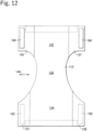
- Fig. 12 is a plan view for illustrating the outer side thereof in a developed state.
- flap parts 131, 133, 135, and 137 extend from a front part 122 and a back part 124 to both sides of a crotch part 126 of an absorptive main body 112 in a around-torso direction illustrated with an arrow 149.
- fastener members 182 and 184 are disposed in the flap parts 131, 133, 135, and 137.
- one fastener member 182 is a loop fastener
- the other fastener member 184 is a hook fastener
- these fastener members 182 and 184 are overlaid with each other for fastening.
- the fastener members 182 and 184 are disposed at a distance from tip ends in the around-torso direction of the flap parts 131, 133, 135, and 137. Thus, hard fastening surfaces of the fastener members 182 and 184 can be prevented from being touched when the fastener members 182 and 184 are fastened. Besides, the fastening between the fastener members 182 and 184 can be released by picking up portions, which protrude to the ends on the tip side in the around-torso direction beyond the fastener members 182, of the flap parts 131 and 135 extending from the back part 124 (see, for example, Patent Literature 1).
- Patent Literature 1 Japanese Patent No. 5411158
- the flap part when the flap part is made of a nonwoven fabric, a portion on the tip side in the around-torso direction of the flap part disposed beyond the fastener member may be folded to attach to the fastening surface of the fastener member, and thus, a part of the fastening surface of the fastener member may be covered.
- the fastening area is insufficient, which causes a problem of weak fastening power.
- the nonwoven fabric of the tip end of the flap part may be caught by the hook portions in some cases.
- a problem to be solved by the present invention is to provide a disposable wearable article that can ensure sufficient fastening power of a fastener member by suppressing folding of a portion protruding to the end on the tip side of a flap part beyond the fastener member of the flap part, and preventing the flap part from covering the fastener member.
- the present invention provides a disposable wearable article having the following configuration for solving the above-described problem.
- the disposable wearable article includes (a) an absorptive main body in which an absorber is disposed between a top sheet and a back sheet; (b) a pair of flap parts that are provided in one of a front part and a back part disposed on both side of a crotch part of the absorptive main body, and extend to both sides in a around-torso direction; and (c) a pair of fastener members that are respectively provided in the pair of flap parts at a distance from tip ends in the around-torso direction of the flap parts to be attachably and detachably joined to an opposing part provided in the absorptive main body.
- Each of the flap parts is made of a thermoplastic nonwoven fabric, and includes, in an extending part between the tip end of the flap part and the fastener member, a thermally-fused part having bending rigidity of the nonwoven fabric increased by thermally fusing the nonwoven fabric.
- each flap part includes a thermally-fused part in a portion protruding to the end on the tip side in the around-torso direction beyond the fastener member, namely, the extending part.
- the thermally-fused part suppresses folding of the end on the tip side of the flap part.
- the end on the tip side in the around-torso direction hereinafter, simply referred to as the "end on the tip side" of the flap part is prevented from covering a fastening surface of the fastener member, and thus, sufficient fastening power of the fastener member can be ensured.
- the thermally-fused part may be formed in a whole region in the around-torso direction of the extending part, or may be formed in a partial region in the around-torso direction of the extending part.
- the thermally-fused part continuously extends from the extending part into a region of the flap part where the fastener member is disposed.
- each of the flap parts includes the thermally-fused part in a plural number linearly extending at a right angle to the tip end of the flap part.
- the thermally-fused part can be easily formed, and the disposable wearable article can be easily mass-produced.
- each of the flap parts includes the thermally-fused part formed in a lattice shape.
- each of the flap parts includes the thermally-fused part formed adjacent to a whole region between a first end and a second end, in a direction crossing the around-torso direction at a right angle, of the tip end of the flap part.
- a disposable wearable article of the present invention can suppress folding of a portion of a flap part protruding to the end on the tip side in a around-torso direction beyond a fastener member (extending part) to prevent the flap part from covering the fastener member, and thus, sufficient fastening power of the fastener member can be ensured.
- Example 1 A disposable wearable article 10 of Example 1 will now be described with reference to Figs. 1 to 5.
- Fig. 1 is a plan view of the disposable wearable article 10, and illustrates the skin surface side thereof in a developed state. As illustrated in Fig. 1 , in the disposable wearable article 10, an absorptive main body 12 is joined to a flap member 14.
- an absorber for absorbing a liquid is disposed between a liquid permeable top sheet and a liquid impermeable back sheet.
- the absorber is disposed centering around a crotch part 12b of the absorptive main body 12 to extend into a back part 12a and a front part 12c on both sides of the crotch part.
- an opposing member 13 is provided on the other side of the top sheet of the absorptive main body 12, namely, on the non-skin surface side.
- the opposing member 13 may be provided in one portion, or in a plurality of portions.
- the opposing member 13 covers a part or the whole of the non-skin surface side of the absorptive main body 12, and is exposed to the non-skin surface side.
- the opposing member 13 forms an opposing part to which a fastener member 16 described below is attachably and detachably joined, and may be, for example, a loop fastener or the like, or a nonwoven fabric sheet or the like.
- a stretchable elastic member 15 is disposed between two thermoplastic nonwoven fabrics.
- the flap member 14 is folded in half along a fold line 14r between side edges 14n and 14m of the two nonwoven fabrics opposing each other, and extends in a around-torso direction 10x illustrated with an arrow 10x.
- a cutout 14k corresponding to a leg opening is formed.
- the elastic member 15 is, for example, a thread rubber or the like, and extends in the around-torso direction 10x.
- Fig. 1 illustrates a state where the elastic member 15 is stretched.
- the back part 12a of the absorptive main body 12 is joined to the center in the around-torso direction 10x of the flap member 14.
- the flap member 14 thus forms a pair of flap parts 14u provided on the back part 12a of the absorptive main body 12, and extending to the both sides in the around-torso direction 10x.
- the opposing member 13 forming the opposing part is provided, for example, on the non-skin surface side of the front part 12c of the absorptive main body 12.
- the front part 12c of the absorptive main body 12 may be joined to the center in the around-torso direction 10x of the flap member 14 instead of the back part 12a of the absorptive main body 12.
- the pair of flap parts 14u are provided in the front part 12c of the absorptive main body 12, and extend to the both sides in the around-torso direction 10x.
- the opposing member 13 forming the opposing part is provided, for example, on the non-skin surface side of the back part 12a of the absorptive main body 12.
- Fig. 2 is an enlarged view of an end portion in the around-torso direction 10x of the flap part 14u of the disposable wearable article 10.
- a fastener member 16 is disposed at a distance from the tip end 14v in the around-torso direction 10x of the flap member 14.
- the fastener member 16 is a hook-and-loop fastener, such as a hook fastener, to be attachably and detachably joined to the opposing member 13.
- the fastener member 16 is joined to the opposing member 13 so as to fasten the flap part 14u onto the front part 12c of the absorptive main body 12.
- the flap part 14u has a thermally-fused part 18 having bending rigidity of the nonwoven fabric increased by thermally fusing the nonwoven fabric of the flap member 14.
- the thermally-fused part 18 is formed in an extending part 14p between the tip end 14v of the flap part 14u and the fastener member 16, and is further formed to extend beyond the extending part 14p continuously into a region of the flap part 14u where the fastener member 16 is disposed.
- the thermally-fused part 18 may be formed only in the extending part 14p.
- the extending part 14p disposed between the tip end 14v of the flap member 14 and the fastener member 16 is made of a nonwoven fabric, and hence is lack of stiffness and easily folded as it is, and therefore, may be folded to be overlaid on the fastening surface of the fastener member 16, and remain to attach to the fastening surface of the fastener member 16 in some cases.
- the fastening area is insufficient, which causes a problem of weak fastening power.
- the thermally-fused part 18 is formed in the extending part 14p, the rigidity of the extending part 14p is increased, and folding of the extending part 14p is suppressed. As a result, the extending part 14p disposed on the tip side of the flap part 14u is prevented from covering the fastening surface of the fastener member 16, and thus, sufficient fastening power of the fastener member 16 can be ensured.
- the thermally-fused part 18 may be formed to be adjacent to only a part of a region between a first end 14a and a second 14b in a direction perpendicular to the around-torso direction of the tip end 14v of the flap part 14u, but is preferably formed to be adjacent to the whole region as illustrated in the drawings.
- the thermally-fused part 18 is formed to be adjacent to the whole region between the first end 14a and the second end 14b, folding of the end on the tip side of the flap part 14u is suppressed in the whole region along the tip end 14V of the flap part 14u. As a result, sufficient fastening power of the fastener member 16 can be more definitely ensured.
- FIGS. 3 and 4 are explanatory diagrams of the processes for producing the disposable wearable article 10.
- a flap member continuous body 14x in which portions corresponding to the flap members 14 are connected to one another is prepared to be conveyed in the lengthwise direction.
- the flap member continuous body 14x is formed by disposing, between nonwoven fabric sheets, a continuous body of the elastic member 15 in a stretched state; mutually joining the nonwoven fabric sheets and the continuous body of the elastic member 15; and then cutting the continuous body of the elastic member 15 at appropriate positions. After the cutting, the elastic member 15 in a stretched state is not disposed in a tip end planned region 14w that is planned to correspond to the tip end of the flap part 14u.
- Fig. 5 is an enlarged view of the vicinity of the tip end planned region 14w.
- a dash-dot line 14k corresponds to a cut planned position 14k in which the flap member continuous body 14x is planned to be cut
- a dash-dot-dot line corresponds to a fastener member disposition region 16k in which the fastener member 16 is planned to be fixed.
- the plural thermally-fused parts 18 cross, at a right angle, the cut planned position 14k to be continuous into the fastener member disposition regions 16k on both sides of the cut planned position 14k.
- the flap member continuous body 14x is cut in the cut planned position 14k, thereby forming a plurality of thermally fused parts 18 linearly extending, and having a right angle to the tip end 14v of the flap part 14u.
- the thermally-fused parts 18 can be easily formed when the flap member continuous body 14x conveyed in the lengthwise direction passes through a thermal fusion device, and therefore, the disposable wearable article 10 can be easily mass-produced.
- a pair of fastener members 16 are disposed on both sides of the cut planned position 14k at a distance from the cut planned position 14k, and are fixed by thermal fusion, adhesion or the like.
- the absorptive main body 12 is fixed on the flap member continuous body 14x by thermal fusion, adhesion or the like.
- the opposing member 13 is precedently provided on the absorptive main body 12.
- the opposing member 13 is provided on the absorptive main body 12. It is noted that the stretchability of the elastic member 15 may be eliminated or reduced by cutting the continuous body of the elastic member 15 in a region where the absorptive main body 12 is fixed.
- the flap member continuous body 14x is cut in the cut planned position 14k illustrated with the dash-dot line 14k in Fig. 4(d) to form individuals of the disposable wearable article 10.
- the disposable wearable articles 10 can be successively formed.
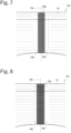
- Figs. 6 to 9 are explanatory diagrams of thermally-fused parts 18a to 18d of Modification Examples 1 to 4 of Example 1.
- Figs. 6 to 9 are enlarged views, similar to Fig. 5 , of the vicinity of the tip end planned region 14w of the flap member continuous body 14x before cutting.
- the thermally-fused parts 18a of Modification Example 1 illustrated in Fig. 6 are formed in a zigzag shape, and diagonally cross (at a non-right angle) the cut planned position 14k and the fastener member disposition region 16k.
- the thermally-fused parts 18a linearly extend between the cut planned position 14k and the fastener member disposition region 16k (namely, a region corresponding to the extending part 14p).
- the thermally-fused parts 18a are formed in a V-shape in the flap part 14u, and linearly extend in the extending part 14p.
- the thermally-fused parts 18b of Modification Example 2 illustrated in Fig. 7 are formed in a further zigzag shape, and diagonally cross (at a non-right angle) the cut planned position 14k and the fastener member disposition region 16k.
- the thermally-fused parts 18b extend in a V-shape between the cut planned position 14k and the fastener member disposition region 16k (namely, a region corresponding to the extending part 14p).
- the thermally-fused parts 18b are formed in a W-shape in the flap part 14u, and extend in a V-shape in the extending part 14p.
- the thermally-fused parts 18c of Modification Example 3 illustrated in Fig. 8 are formed in a lattice shape, and include a plurality of first linear portions extending in parallel to the cut planned position 14k, and a plurality of second linear portions crossing, at a right angle, the cut planned position 14k.
- the thermally-fused parts 18c in a lattice shape suppresses folding in all directions of the end on the tip side of the flap part 14u. As a result, sufficient fastening power of the fastener member 16 can be more definitely ensured.
- the thermally-fused parts 18d of Modification Example 4 illustrated in Fig. 9 are formed in a diagonal lattice shape, and include a plurality of first and second linear portions diagonally crossing the cut planned position 14k and parallel to one another. Although the first and second linear portions cross each other at a right angle in the drawing, the first and second linear portions may be diagonally (at a non-right angle) cross each other.
- the thermally-fused parts 18d in a lattice shape suppresses folding in all directions of the end on the tip side of the flap part 14u. As a result, sufficient fastening power of the fastener member 16 can be more definitely ensured.
- Fig. 10 is a plan view of the disposable wearable article 10a.
- an adsorptive body 12 similar to that of Example 1 is joined to a flap member 20 in which a stretchable elastic member 21 is disposed between two thermoplastic nonwoven fabrics.
- a pair of first flap parts 22 extending to both sides in the around-torso direction are provided in a back part 12a of the absorptive main body 12, and a pair of second flap parts 24 extending to the both sides in the around-torso direction are provided in a front part 12c of the absorptive main body 12.
- a pair of fastener members 26 are respectively provided at a distance from tip ends 22v in the around-torso direction of the first flap parts 22.
- the fastener members 26 are attachably and detachably joined to the second flap parts 24.
- the second flap parts 24 are opposing parts provided on the absorptive main body 12.
- opposing members of a loop fastener or the like to be joined to the fastener members 26 of a hook fastener or the like may be provided.
- Each of the first flap parts 22 is made of a thermoplastic nonwoven fabric, and has, in an extending part 23 between the tip end 22v of the first flap part 22 and the fastener member 26, a thermally-fused part 28 having bending rigidity of the nonwoven fabric increased by thermally fusing the nonwoven fabric.
- the thermally-fused part 28 extends, beyond the extending part 23, continuously into a region where the fastener member 26 of the first flap part 22 is disposed.
- the thermally-fused part 28 may be formed only in the extending part 23.
- the thermally-fused part 28 can suppress folding of the portion of the first flap part 22 protruding to the end on the tip side in the around-torso direction beyond the fastener member 26, namely, the extending part 23, and prevents the first flap part 22 from covering the fastener member 26, and thus, sufficient fastening power of the fastener member 26 can be ensured.
- thermally-fused parts in a zigzag shape or lattice shape may be formed in the same manner as in Modification Examples 1 to 4 described above.
- the thermally-fused part may be formed in a curved shape, or in a staggered shape.
- the thermally-fused part may be formed at a distance from the tip end 14v of the flap part 14u, or may be formed at a distance from the region where the fastener member 16 is disposed.
- the configurations described in Example 1, Modification Examples 1 to 4, and Example 2 may be appropriately combined.
Landscapes
- Health & Medical Sciences (AREA)
- Epidemiology (AREA)
- Engineering & Computer Science (AREA)
- Biomedical Technology (AREA)
- Heart & Thoracic Surgery (AREA)
- Vascular Medicine (AREA)
- Life Sciences & Earth Sciences (AREA)
- Animal Behavior & Ethology (AREA)
- General Health & Medical Sciences (AREA)
- Public Health (AREA)
- Veterinary Medicine (AREA)
- Absorbent Articles And Supports Therefor (AREA)
Applications Claiming Priority (2)
| Application Number | Priority Date | Filing Date | Title |
|---|---|---|---|
| JP2021133594 | 2021-08-18 | ||
| PCT/JP2022/024339 WO2023021833A1 (fr) | 2021-08-18 | 2022-06-17 | Article jetable pouvant être porté |
Publications (4)
| Publication Number | Publication Date |
|---|---|
| EP4360603A1 true EP4360603A1 (fr) | 2024-05-01 |
| EP4360603A4 EP4360603A4 (fr) | 2024-09-11 |
| EP4360603B1 EP4360603B1 (fr) | 2025-08-06 |
| EP4360603C0 EP4360603C0 (fr) | 2025-08-06 |
Family
ID=85240506
Family Applications (1)
| Application Number | Title | Priority Date | Filing Date |
|---|---|---|---|
| EP22858157.5A Active EP4360603B1 (fr) | 2021-08-18 | 2022-06-17 | Article jetable pouvant être porté |
Country Status (5)
| Country | Link |
|---|---|
| US (1) | US20250099306A1 (fr) |
| EP (1) | EP4360603B1 (fr) |
| JP (1) | JP7737460B2 (fr) |
| CN (1) | CN117858688A (fr) |
| WO (1) | WO2023021833A1 (fr) |
Family Cites Families (9)
| Publication number | Priority date | Publication date | Assignee | Title |
|---|---|---|---|---|
| EP0803602A4 (fr) * | 1995-01-12 | 2002-06-26 | Japan Absorbent Tech Inst | Corps elastique composite a caracteristiques d'elongation multietagees et son procede de fabrication |
| US5938650A (en) * | 1995-08-09 | 1999-08-17 | Fibertech Group, Inc. | Absorbent core for absorbing body liquids and method |
| US7988682B2 (en) * | 2002-04-02 | 2011-08-02 | Sca Hygiene Products Ab | Prefastened absorbent product with releasable fasteners and flaps having welds |
| JP5009039B2 (ja) | 2007-04-27 | 2012-08-22 | 大王製紙株式会社 | 使い捨て紙おむつ |
| US9089454B2 (en) | 2007-12-14 | 2015-07-28 | Kimberly-Clark Worldwide, Inc. | Absorbent article having a functional and partially encircling waistband |
| WO2013122939A1 (fr) * | 2012-02-13 | 2013-08-22 | The Procter & Gamble Company | Vêtement à enfiler jetable |
| US9504610B2 (en) * | 2013-03-15 | 2016-11-29 | The Procter & Gamble Company | Methods for forming absorbent articles with nonwoven substrates |
| US9532908B2 (en) * | 2013-09-20 | 2017-01-03 | The Procter & Gamble Company | Textured laminate surface, absorbent articles with textured laminate structure, and for manufacturing |
| JP6123860B2 (ja) | 2015-09-17 | 2017-05-10 | 王子ホールディングス株式会社 | ベルト型使い捨ておむつ |
-
2022
- 2022-06-17 CN CN202280056083.9A patent/CN117858688A/zh active Pending
- 2022-06-17 JP JP2023542240A patent/JP7737460B2/ja active Active
- 2022-06-17 WO PCT/JP2022/024339 patent/WO2023021833A1/fr not_active Ceased
- 2022-06-17 EP EP22858157.5A patent/EP4360603B1/fr active Active
- 2022-06-17 US US18/290,984 patent/US20250099306A1/en active Pending
Also Published As
| Publication number | Publication date |
|---|---|
| JPWO2023021833A1 (fr) | 2023-02-23 |
| EP4360603B1 (fr) | 2025-08-06 |
| EP4360603A4 (fr) | 2024-09-11 |
| EP4360603C0 (fr) | 2025-08-06 |
| US20250099306A1 (en) | 2025-03-27 |
| JP7737460B2 (ja) | 2025-09-10 |
| CN117858688A (zh) | 2024-04-09 |
| WO2023021833A1 (fr) | 2023-02-23 |
Similar Documents
| Publication | Publication Date | Title |
|---|---|---|
| US8114058B2 (en) | Process for making disposable absorbent article | |
| EP2433601B2 (fr) | Procédé de fabrication d'un article vestimentaire jetable | |
| AU721251B2 (en) | Method for making components of absorbent undergarment | |
| US7870651B2 (en) | Elasticized side members | |
| US5906008A (en) | Disposable diaper | |
| AU2011241721B2 (en) | Diaper cover and disposable diaper | |
| US9433540B2 (en) | Disposable pull-on diaper having interior elastic sheets and exterior non-elastic sheets | |
| US20070016155A1 (en) | Shaped side panel for disposable absorbent article | |
| US20120238989A1 (en) | Disposable diaper | |
| EP2301501A1 (fr) | Procédé de fabrication d'un article à porter et article à porter | |
| JP2000014702A (ja) | 使い捨ておむつ | |
| US9132041B2 (en) | Disposable worn article in pants form with cut-outs and method for manufacturing same | |
| CN101803975B (zh) | 一次性穿着物品的制造方法 | |
| EP2441422A1 (fr) | Procédé de production de couches jetables | |
| CA2213802C (fr) | Couche jetable | |
| US7753900B2 (en) | Disposable pull-on diaper and process for making the same | |
| EP4360603A1 (fr) | Article jetable pouvant être porté | |
| JP2005312707A (ja) | ファスニングテープの製造方法及び該ファスニングテープを用いた使い捨ておむつの製造方法 | |
| EP2520264B1 (fr) | Article à porter de type couche-culotte | |
| JP5202282B2 (ja) | シートの製造方法 | |
| EP2221032B1 (fr) | Article pour incontinents | |
| CN101795652A (zh) | 吸收性物品 | |
| EP4417172A1 (fr) | Article à porter sur soi et son procédé de fabrication | |
| WO2023153474A1 (fr) | Article vestimentaire jetable | |
| KR20250054983A (ko) | 흡수 팬츠 |
Legal Events
| Date | Code | Title | Description |
|---|---|---|---|
| STAA | Information on the status of an ep patent application or granted ep patent |
Free format text: STATUS: THE INTERNATIONAL PUBLICATION HAS BEEN MADE |
|
| PUAI | Public reference made under article 153(3) epc to a published international application that has entered the european phase |
Free format text: ORIGINAL CODE: 0009012 |
|
| STAA | Information on the status of an ep patent application or granted ep patent |
Free format text: STATUS: REQUEST FOR EXAMINATION WAS MADE |
|
| 17P | Request for examination filed |
Effective date: 20240126 |
|
| AK | Designated contracting states |
Kind code of ref document: A1 Designated state(s): AL AT BE BG CH CY CZ DE DK EE ES FI FR GB GR HR HU IE IS IT LI LT LU LV MC MK MT NL NO PL PT RO RS SE SI SK SM TR |
|
| A4 | Supplementary search report drawn up and despatched |
Effective date: 20240813 |
|
| RIC1 | Information provided on ipc code assigned before grant |
Ipc: A61F 13/56 20060101ALI20240807BHEP Ipc: A61F 13/49 20060101AFI20240807BHEP |
|
| DAV | Request for validation of the european patent (deleted) | ||
| DAX | Request for extension of the european patent (deleted) | ||
| GRAP | Despatch of communication of intention to grant a patent |
Free format text: ORIGINAL CODE: EPIDOSNIGR1 |
|
| STAA | Information on the status of an ep patent application or granted ep patent |
Free format text: STATUS: GRANT OF PATENT IS INTENDED |
|
| GRAS | Grant fee paid |
Free format text: ORIGINAL CODE: EPIDOSNIGR3 |
|
| INTG | Intention to grant announced |
Effective date: 20250416 |
|
| RAP3 | Party data changed (applicant data changed or rights of an application transferred) |
Owner name: ZUIKO CORPORATION |
|
| GRAA | (expected) grant |
Free format text: ORIGINAL CODE: 0009210 |
|
| STAA | Information on the status of an ep patent application or granted ep patent |
Free format text: STATUS: THE PATENT HAS BEEN GRANTED |
|
| AK | Designated contracting states |
Kind code of ref document: B1 Designated state(s): AL AT BE BG CH CY CZ DE DK EE ES FI FR GB GR HR HU IE IS IT LI LT LU LV MC MK MT NL NO PL PT RO RS SE SI SK SM TR |
|
| REG | Reference to a national code |
Ref country code: GB Ref legal event code: FG4D |
|
| REG | Reference to a national code |
Ref country code: CH Ref legal event code: EP |
|
| REG | Reference to a national code |
Ref country code: IE Ref legal event code: FG4D |
|
| REG | Reference to a national code |
Ref country code: DE Ref legal event code: R096 Ref document number: 602022019149 Country of ref document: DE |
|
| U01 | Request for unitary effect filed |
Effective date: 20250812 |
|
| U07 | Unitary effect registered |
Designated state(s): AT BE BG DE DK EE FI FR IT LT LU LV MT NL PT RO SE SI Effective date: 20250822 |
|
| PG25 | Lapsed in a contracting state [announced via postgrant information from national office to epo] |
Ref country code: IS Free format text: LAPSE BECAUSE OF FAILURE TO SUBMIT A TRANSLATION OF THE DESCRIPTION OR TO PAY THE FEE WITHIN THE PRESCRIBED TIME-LIMIT Effective date: 20251206 |
|
| PG25 | Lapsed in a contracting state [announced via postgrant information from national office to epo] |
Ref country code: NO Free format text: LAPSE BECAUSE OF FAILURE TO SUBMIT A TRANSLATION OF THE DESCRIPTION OR TO PAY THE FEE WITHIN THE PRESCRIBED TIME-LIMIT Effective date: 20251106 |
|
| PG25 | Lapsed in a contracting state [announced via postgrant information from national office to epo] |
Ref country code: HR Free format text: LAPSE BECAUSE OF FAILURE TO SUBMIT A TRANSLATION OF THE DESCRIPTION OR TO PAY THE FEE WITHIN THE PRESCRIBED TIME-LIMIT Effective date: 20250806 |
|
| PG25 | Lapsed in a contracting state [announced via postgrant information from national office to epo] |
Ref country code: GR Free format text: LAPSE BECAUSE OF FAILURE TO SUBMIT A TRANSLATION OF THE DESCRIPTION OR TO PAY THE FEE WITHIN THE PRESCRIBED TIME-LIMIT Effective date: 20251107 |
|
| PG25 | Lapsed in a contracting state [announced via postgrant information from national office to epo] |
Ref country code: PL Free format text: LAPSE BECAUSE OF FAILURE TO SUBMIT A TRANSLATION OF THE DESCRIPTION OR TO PAY THE FEE WITHIN THE PRESCRIBED TIME-LIMIT Effective date: 20250806 |
|
| PG25 | Lapsed in a contracting state [announced via postgrant information from national office to epo] |
Ref country code: RS Free format text: LAPSE BECAUSE OF FAILURE TO SUBMIT A TRANSLATION OF THE DESCRIPTION OR TO PAY THE FEE WITHIN THE PRESCRIBED TIME-LIMIT Effective date: 20251106 |
|
| PG25 | Lapsed in a contracting state [announced via postgrant information from national office to epo] |
Ref country code: ES Free format text: LAPSE BECAUSE OF FAILURE TO SUBMIT A TRANSLATION OF THE DESCRIPTION OR TO PAY THE FEE WITHIN THE PRESCRIBED TIME-LIMIT Effective date: 20250806 |
|
| PG25 | Lapsed in a contracting state [announced via postgrant information from national office to epo] |
Ref country code: SM Free format text: LAPSE BECAUSE OF FAILURE TO SUBMIT A TRANSLATION OF THE DESCRIPTION OR TO PAY THE FEE WITHIN THE PRESCRIBED TIME-LIMIT Effective date: 20250806 |
|
| PG25 | Lapsed in a contracting state [announced via postgrant information from national office to epo] |
Ref country code: CZ Free format text: LAPSE BECAUSE OF FAILURE TO SUBMIT A TRANSLATION OF THE DESCRIPTION OR TO PAY THE FEE WITHIN THE PRESCRIBED TIME-LIMIT Effective date: 20250806 |
|
| PG25 | Lapsed in a contracting state [announced via postgrant information from national office to epo] |
Ref country code: SK Free format text: LAPSE BECAUSE OF FAILURE TO SUBMIT A TRANSLATION OF THE DESCRIPTION OR TO PAY THE FEE WITHIN THE PRESCRIBED TIME-LIMIT Effective date: 20250806 |