EP4361629A1 - Dispositif de mesure avec un port pour bandelette conçu pour le piégeage de fluide - Google Patents
Dispositif de mesure avec un port pour bandelette conçu pour le piégeage de fluide Download PDFInfo
- Publication number
- EP4361629A1 EP4361629A1 EP23204377.8A EP23204377A EP4361629A1 EP 4361629 A1 EP4361629 A1 EP 4361629A1 EP 23204377 A EP23204377 A EP 23204377A EP 4361629 A1 EP4361629 A1 EP 4361629A1
- Authority
- EP
- European Patent Office
- Prior art keywords
- measurement device
- test strip
- opening portion
- protective cover
- insertion aperture
- Prior art date
- Legal status (The legal status is an assumption and is not a legal conclusion. Google has not performed a legal analysis and makes no representation as to the accuracy of the status listed.)
- Granted
Links
Images




Classifications
-
- A—HUMAN NECESSITIES
- A61—MEDICAL OR VETERINARY SCIENCE; HYGIENE
- A61B—DIAGNOSIS; SURGERY; IDENTIFICATION
- A61B5/00—Measuring for diagnostic purposes; Identification of persons
- A61B5/15—Devices for taking samples of blood
- A61B5/150007—Details
- A61B5/150374—Details of piercing elements or protective means for preventing accidental injuries by such piercing elements
- A61B5/150534—Design of protective means for piercing elements for preventing accidental needle sticks, e.g. shields, caps, protectors, axially extensible sleeves, pivotable protective sleeves
- A61B5/150633—Protective sleeves which are axially extensible, e.g. sleeves connected to, or integrated in, the piercing or driving device; pivotable protective sleeves
-
- G—PHYSICS
- G01—MEASURING; TESTING
- G01N—INVESTIGATING OR ANALYSING MATERIALS BY DETERMINING THEIR CHEMICAL OR PHYSICAL PROPERTIES
- G01N33/00—Investigating or analysing materials by specific methods not covered by groups G01N1/00 - G01N31/00
- G01N33/48—Biological material, e.g. blood, urine; Haemocytometers
- G01N33/483—Physical analysis of biological material
- G01N33/487—Physical analysis of biological material of liquid biological material
- G01N33/49—Blood
-
- G—PHYSICS
- G01—MEASURING; TESTING
- G01N—INVESTIGATING OR ANALYSING MATERIALS BY DETERMINING THEIR CHEMICAL OR PHYSICAL PROPERTIES
- G01N33/00—Investigating or analysing materials by specific methods not covered by groups G01N1/00 - G01N31/00
- G01N33/48—Biological material, e.g. blood, urine; Haemocytometers
- G01N33/50—Chemical analysis of biological material, e.g. blood, urine; Testing involving biospecific ligand binding methods; Immunological testing
- G01N33/66—Chemical analysis of biological material, e.g. blood, urine; Testing involving biospecific ligand binding methods; Immunological testing involving blood sugars, e.g. galactose
-
- B—PERFORMING OPERATIONS; TRANSPORTING
- B01—PHYSICAL OR CHEMICAL PROCESSES OR APPARATUS IN GENERAL
- B01L—CHEMICAL OR PHYSICAL LABORATORY APPARATUS FOR GENERAL USE
- B01L3/00—Containers or dishes for laboratory use, e.g. laboratory glassware; Droppers
- B01L3/50—Containers for the purpose of retaining a material to be analysed, e.g. test tubes
- B01L3/502—Containers for the purpose of retaining a material to be analysed, e.g. test tubes with fluid transport, e.g. in multi-compartment structures
- B01L3/5023—Containers for the purpose of retaining a material to be analysed, e.g. test tubes with fluid transport, e.g. in multi-compartment structures with a sample being transported to, and subsequently stored in an absorbent for analysis
-
- G—PHYSICS
- G01—MEASURING; TESTING
- G01N—INVESTIGATING OR ANALYSING MATERIALS BY DETERMINING THEIR CHEMICAL OR PHYSICAL PROPERTIES
- G01N27/00—Investigating or analysing materials by the use of electric, electrochemical, or magnetic means
- G01N27/26—Investigating or analysing materials by the use of electric, electrochemical, or magnetic means by investigating electrochemical variables; by using electrolysis or electrophoresis
- G01N27/28—Electrolytic cell components
- G01N27/30—Electrodes, e.g. test electrodes; Half-cells
- G01N27/327—Biochemical electrodes, e.g. electrical or mechanical details for in vitro measurements
- G01N27/3271—Amperometric enzyme electrodes for analytes in body fluids, e.g. glucose in blood
- G01N27/3273—Devices therefor, e.g. test element readers, circuitry
-
- G—PHYSICS
- G01—MEASURING; TESTING
- G01N—INVESTIGATING OR ANALYSING MATERIALS BY DETERMINING THEIR CHEMICAL OR PHYSICAL PROPERTIES
- G01N33/00—Investigating or analysing materials by specific methods not covered by groups G01N1/00 - G01N31/00
- G01N33/48—Biological material, e.g. blood, urine; Haemocytometers
- G01N33/483—Physical analysis of biological material
- G01N33/487—Physical analysis of biological material of liquid biological material
- G01N33/48707—Physical analysis of biological material of liquid biological material by electrical means
-
- G—PHYSICS
- G01—MEASURING; TESTING
- G01N—INVESTIGATING OR ANALYSING MATERIALS BY DETERMINING THEIR CHEMICAL OR PHYSICAL PROPERTIES
- G01N33/00—Investigating or analysing materials by specific methods not covered by groups G01N1/00 - G01N31/00
- G01N33/48—Biological material, e.g. blood, urine; Haemocytometers
- G01N33/483—Physical analysis of biological material
- G01N33/487—Physical analysis of biological material of liquid biological material
- G01N33/4875—Details of handling test elements, e.g. dispensing or storage, not specific to a particular test method
-
- A—HUMAN NECESSITIES
- A61—MEDICAL OR VETERINARY SCIENCE; HYGIENE
- A61B—DIAGNOSIS; SURGERY; IDENTIFICATION
- A61B2562/00—Details of sensors; Constructional details of sensor housings or probes; Accessories for sensors
- A61B2562/02—Details of sensors specially adapted for in-vivo measurements
- A61B2562/0295—Strip shaped analyte sensors for apparatus classified in A61B5/145 or A61B5/157
-
- B—PERFORMING OPERATIONS; TRANSPORTING
- B01—PHYSICAL OR CHEMICAL PROCESSES OR APPARATUS IN GENERAL
- B01L—CHEMICAL OR PHYSICAL LABORATORY APPARATUS FOR GENERAL USE
- B01L2200/00—Solutions for specific problems relating to chemical or physical laboratory apparatus
- B01L2200/02—Adapting objects or devices to another
- B01L2200/025—Align devices or objects to ensure defined positions relative to each other
-
- B—PERFORMING OPERATIONS; TRANSPORTING
- B01—PHYSICAL OR CHEMICAL PROCESSES OR APPARATUS IN GENERAL
- B01L—CHEMICAL OR PHYSICAL LABORATORY APPARATUS FOR GENERAL USE
- B01L2200/00—Solutions for specific problems relating to chemical or physical laboratory apparatus
- B01L2200/06—Fluid handling related problems
- B01L2200/0615—Loss of fluid by dripping
-
- B—PERFORMING OPERATIONS; TRANSPORTING
- B01—PHYSICAL OR CHEMICAL PROCESSES OR APPARATUS IN GENERAL
- B01L—CHEMICAL OR PHYSICAL LABORATORY APPARATUS FOR GENERAL USE
- B01L2300/00—Additional constructional details
- B01L2300/04—Closures and closing means
- B01L2300/046—Function or devices integrated in the closure
-
- B—PERFORMING OPERATIONS; TRANSPORTING
- B01—PHYSICAL OR CHEMICAL PROCESSES OR APPARATUS IN GENERAL
- B01L—CHEMICAL OR PHYSICAL LABORATORY APPARATUS FOR GENERAL USE
- B01L2300/00—Additional constructional details
- B01L2300/06—Auxiliary integrated devices, integrated components
- B01L2300/0627—Sensor or part of a sensor is integrated
- B01L2300/0645—Electrodes
-
- B—PERFORMING OPERATIONS; TRANSPORTING
- B01—PHYSICAL OR CHEMICAL PROCESSES OR APPARATUS IN GENERAL
- B01L—CHEMICAL OR PHYSICAL LABORATORY APPARATUS FOR GENERAL USE
- B01L2300/00—Additional constructional details
- B01L2300/08—Geometry, shape and general structure
- B01L2300/0809—Geometry, shape and general structure rectangular shaped
- B01L2300/0825—Test strips
-
- B—PERFORMING OPERATIONS; TRANSPORTING
- B01—PHYSICAL OR CHEMICAL PROCESSES OR APPARATUS IN GENERAL
- B01L—CHEMICAL OR PHYSICAL LABORATORY APPARATUS FOR GENERAL USE
- B01L2300/00—Additional constructional details
- B01L2300/12—Specific details about materials
- B01L2300/123—Flexible; Elastomeric
-
- B—PERFORMING OPERATIONS; TRANSPORTING
- B01—PHYSICAL OR CHEMICAL PROCESSES OR APPARATUS IN GENERAL
- B01L—CHEMICAL OR PHYSICAL LABORATORY APPARATUS FOR GENERAL USE
- B01L2400/00—Moving or stopping fluids
- B01L2400/04—Moving fluids with specific forces or mechanical means
- B01L2400/0403—Moving fluids with specific forces or mechanical means specific forces
- B01L2400/0406—Moving fluids with specific forces or mechanical means specific forces capillary forces
Definitions
- the present invention relates to a measurement device for measuring a sample in a liquid state, and particularly to a blood sugar measurement device.
- various measurement devices have been provided in which a disposable test strip is inserted into an insertion aperture of a blood sugar measurement device, a blood sample is spotted onto the test strip, and a blood sugar value of the blood sample is measured.
- a blood sample of an amount exceeding a proper amount is spotted onto the test strip, the surplus blood sample passes along the test strip and enters into the measurement device, which leads to soiling and malfunction of the measurement device.
- JP-A Japanese Patent Application Laid-Open
- a pair of doors are provided that allow insertion of a test strip into the device.
- the pair of doors abut against the test strip, as a result of which the opening of the device is closed up to be liquid-tight.
- An embodiment of the present invention provides a measurement device that can, with a simple structure, prevent a surplus liquid sample, for example a blood sample, spotted onto a test strip from entering into the measurement device through an insertion aperture of the measurement device, and thus can prevent soiling and malfunction.
- a first aspect of the invention provides a measurement device to which a protective cover is attached.
- the measurement device is provided with an insertion aperture for insertion of a test strip onto which a liquid sample is spotted.
- the protective cover is attached to the measurement device so as to cover a region including surroundings of the insertion aperture, and the protective cover is provided with an opening portion into which the test strip is insertable.
- the opening portion and the insertion aperture are relatively positioned such that, in a state in which the test strip is inserted through the opening portion and inserted into the insertion aperture, an upper face and a lower face of the test strip both abut against the protective cover.
- a measurement device that can prevent a surplus blood sample spotted onto a test strip from entering into the measurement device through an insertion aperture of the measurement device, and thus can prevent soiling and malfunction.
- the present disclosure relates to a measurement device for measuring a liquid sample but, for convenience of description, a blood sugar measurement device that measures a blood sample serving as the liquid sample is described as a nonlimiting example of the measurement device.
- Fig. 1 is a front-upper perspective view of the measurement device 10 according to an exemplary embodiment of the present invention.
- Fig. 2 is a front-upper perspective view showing the measurement device 10 of Fig. 1 in a state in which a protective cover 20 is removed.
- the measurement device 10 is structured with a substantially box-shaped casing body 101 and a measuring instrument 102 (see Fig. 7 ). Four corners of the casing body 101 are formed in curved shapes.
- the measuring instrument 102 measures a test strip 50 which is described below (see Fig. 8 ).
- the casing body 101 is a protective member enclosing the measuring instrument 102, and the casing body 101 forms the exterior of the measurement device 10.
- a display unit 13 is formed at a top face of the casing body 101.
- a user views measurement results of the measuring instrument 102 via the display unit 13.
- the protective cover 20 which is a separate body, is attached to an end portion of the measurement device 10 at which the test strip 50 is to be inserted.
- the side at which the protective cover 20 is provided is referred to as a "front face” or a "forward face”, and the opposite side of the measurement device 10 is referred to as a "rear face”.
- a direction connecting the front face (forward face) and rear face is referred to as a "front-rear direction”.
- a direction toward the display unit 13 is referred to as "upward” and the opposite direction is referred to as "downward”.
- a direction connecting upward and downward is referred to as a "vertical direction”.
- a direction that is orthogonal to the front-rear direction and the vertical direction is referred to as a "left-right direction”.
- an insertion aperture 12 is provided in a central portion of the front face side of the measurement device 10.
- the insertion aperture 12 is for insertion of the test strip 50, onto which a liquid sample is spotted.
- the insertion aperture 12 is formed in a front face end portion of the measurement device 10 as a slit that extends in the left-right direction.
- an opening portion 22 into which the test strip 50 can be inserted is provided at a central portion of the protective cover 20.
- the opening portion 22 is formed in the central portion of the protective cover 20 as a slit that extends in the left-right direction. The opening portion 22 penetrates between the front and rear of the protective cover 20.
- the protective cover 20 is attached to an end portion at the front face side of the measurement device 10 so as to cover a region that includes the surroundings of the insertion aperture 12 in the front face side of the measurement device 10. Relative positions of the opening portion 22 and the insertion aperture 12 in the state in which the protective cover 20 is attached to the measurement device 10 are described in more detail below.
- Fig. 3 is a front-upper perspective view of the protective cover 20
- Fig. 4 is a front view of the protective cover 20.
- an end portion at the front face side of the measurement device 10 assumes a shape in which a central portion projects forward further than both left and right ends, and both the left and right ends are smoothly curved toward the rear face side from the central portion.
- the protective cover 20 assumes a shape that is curved toward the rear side to match the curvature of the front face side of the measurement device 10.
- the protective cover 20 for the measurement device 10 is curved such that the rear face side of the protective cover 20 is recessed to match the shape of the region of the end portion that includes the surroundings of the insertion aperture 12.
- the protective cover 20 is provided with the opening portion 22, which enables insertion of the test strip 50.
- Greatly curved portions at the rear face side of both the left and right ends of the protective cover 20 serve as side guards 21 that cover corner portions at both the left and right ends of the casing body 101.
- Means for attaching the protective cover 20 to the measurement device 10 are not limited; means for tightly fitting the side guards 21 and the corner portions at both the left and right ends of the casing body 101 to each other or the like may be provided.
- a plurality of front face side ribs 25a are formed from a front face side lower end edge of the opening portion 22.
- the front face side ribs 25a extend downward and protrude forward.
- upper end edges of the plurality of front face side ribs 25a are formed to be coplanar with and connected with the front face side lower edge of the opening portion 22.
- interstices 25b are formed between the front face side ribs 25a in elongated slit shapes.
- the plurality of front face side ribs 25a and the plurality of interstices 25b formed between the adjacent front face side ribs 25a constitute a second drawing portion 25, into which a liquid sample is drawn by capillary force.
- the plurality of interstices 25b of the second drawing portion 25 that are between the plurality of ribs connecting to the front face side lower edge of the opening portion 22 act as capillaries.
- a surplus liquid sample arriving at the second drawing portion 25 may be drawn into the interstices 25b of the second drawing portion 25 by the capillary effect and accommodated (held) there by surface tension.
- the second drawing portion 25 projects in the front face direction relative to the opening portion 22.
- two, five, six or the like of the plurality of ribs and plurality of interstices of respective drawing portions are illustrated in the drawings but this does not limit the number thereof, which may be selected according to the width of the opening portion 22.
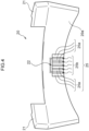
- Fig. 5 is a rear-upper perspective view of the protective cover 20 and Fig. 6 is a rear view of the protective cover 20.
- the rear face side 20b is curved so to be recessed.
- the opening portion 22 is disposed at a central portion of the rear face side 20b of the protective cover 20.
- a plurality of rear face side ribs 23a are formed from a rear face side lower edge of the opening portion 22.
- the rear face side ribs 23a extend downward and protrude rearward.
- upper end edges of the plurality of rear face side ribs 23a are formed to be coplanar with and connected with the rear face side lower edge of the opening portion 22.
- Interstices 23b are formed between the rear face side ribs 23a in elongated slit shapes.
- the plurality of rear face side ribs 23a and the plurality of interstices 23b formed between the adjacent rear face side ribs 23a constitute a first drawing portion 23 into which a liquid sample is drawn by capillary force.
- the plurality of interstices 23b of the first drawing portion 23 that are between the plurality of ribs connecting to the rear face side lower edge of the opening portion 22 act as capillaries.
- a surplus liquid sample arriving at the first drawing portion 23 may be drawn into the interstices 23b of the first drawing portion 23 by the capillary effect and accommodated there by surface tension. As shown in Fig.
- the first drawing portion 23 projects in the rear face direction relative to the opening portion 22.
- a flange 29 protrudes to the rear face side from a lower edge of the protective cover 20.
- Lower end edges of the rear face side ribs 23a are spaced apart from an upper face of the flange 29 and are not linked thereto.
- a plurality of upward ribs 26a are formed from a rear face side upper edge of the opening portion 22.
- the upward ribs 26a extend upward and protrude rearward.
- lower end edges of the plurality of upward ribs 26a are formed to be coplanar with and connected with the rear face side upper edge of the opening portion 22.
- Interstices 26b are formed between the upward ribs 26a in long, narrow slit shapes.
- the plurality of upward ribs 26a and the plurality of interstices 26b formed between the upward ribs 26a constitute a third drawing portion 26 for drawing a liquid sample by capillary force.
- inclined ribs 28a are formed from the lower ends of the upward ribs 26a that are disposed at both the left and right ends of the third drawing portion 26 and from the upper ends of the rear face side ribs 23a that are disposed at both the left and right ends of the first drawing portion 23.
- the inclined ribs 28a are angled downward toward the sides. Lower ends of the inclined ribs 28a are spaced apart from the upper face of the flange 29 and are not linked thereto.
- both left and right ends of the opening portion 22 are surrounded by the corresponding pairs of the inclined ribs 28a.
- the surplus liquid sample is drawn toward the flange 29 by slit-shaped interstices 28b that are formed between the pairs of inclined ribs 28a.
- an inclined drawing portion 28 is formed by the pair of inclined ribs 28a, which extend at an angle downward to the side from the respective end portion of the opening portion 22, and the interstice 28b between the pair of inclined ribs 28a.
- the opening portion 22 is surrounded by the first drawing portion 23, the third drawing portion 26 and the respective inclined drawing portions 28 at left and right. As described later, whatever position of the opening portion 22 a surplus liquid sample entering through the opening portion 22 enters from, that liquid sample is drawn and accommodated by one or more of the interstices 23b, the interstices 26b and the interstices 28b. The sample that cannot be accommodated in the interstices 23b and 28b may be drawn to the flange 29 and accumulated at the flange 29.
- the rear face side ribs 23a and inclined ribs 28a extend downward from the opening portion 22 towards the flange 29 but a distance is left open between the rear face side ribs 23a and inclined ribs 28a and the flange 29.
- a space at the upper face of the flange 29 is not closed up and large amounts of the sample may be accumulated at the upper face of the flange 29 by surface tension. Furthermore, substantially triangular spaces are formed between the flange 29, the rear face side ribs 23a at both ends and the inclined ribs 28a, and these triangular spaces are linked with the space at the upper face of the flange 29. Thereby, even larger amounts of the sample may be accommodated. Therefore, the spaces at the upper face of the flange 29 including the substantially triangular spaces described above are referred to as liquid sumps 24 that accommodate a liquid sample that overflows from the first drawing portion 23.
- Fig. 7 is a section along VII-VII in Fig. 1 . That is, Fig. 7 is a section cut along the center of the opening portion 22, showing a magnification of a vicinity of the opening portion 22 and the insertion aperture 12. As is shown in Fig. 7 , in the state in which the protective cover 20 is attached to the casing body 101 enclosing the measuring instrument 102, the opening portion 22 is disposed at the upper side in the vertical direction relative to the insertion aperture 12. As shown in Fig. 7 , the lower edge of the opening portion 22 is at the upper side relative to an upper edge of the insertion aperture 12 in the vertical direction. Moreover, beveling 12a is formed at edges of the insertion aperture 12.
- the beveling 12a smoothly links from the upper edge and lower edge of the insertion aperture 12 to an outer wall of the casing body 101. As shown in Fig. 7 , the beveling 12a is formed as inclined surfaces. Moreover, an upper edge of the beveling 12a is disposed at the upper side relative to the lower edge of the opening portion 22. A portion of the beveling 12a is superposed in the front-rear direction with the lower edge of the opening portion 22. Furthermore, a deep interior space at the rear face side of the insertion aperture 12 serves as a test strip accommodation portion 14 in which the test strip 50 (see Fig. 8 ) is accommodated. Deeper inside, terminals 15 are provided that electronically connect with an electrode portion 52, which is described later.
- the lower edge of the opening portion 22 is disposed at the upper side relative to the upper edge of the insertion aperture 12, but the upper edge of the insertion aperture 12 may be formed at the upper side relative to the lower edge of the opening portion 22.
- a height difference between the upper edge of the insertion aperture 12 and the lower edge of the opening portion 22 is specified to be smaller than a thickness of the test strip 50. Note that, in this case, if the thickness of the test strip 50 illustrated in Fig. 8 is represented by h, the difference between the upper edge of the insertion aperture 12 and the lower edge of the opening portion 22 is smaller than the thickness h.
- the test strip 50 is curved when inserted through the opening portion 22 into the insertion aperture 12.
- the rear face side ribs 23a and upward ribs 26a protruding rearward from the rear face side 20b of the protective cover 20, and specifically connecting to the edge portions of the opening portion 22, are spaced apart from the outer face of the casing body 101 that includes the insertion aperture 12, assuring a predetermined distance therebetween. Therefore, a liquid sample pooling in the ribs and spaces of the protective cover 20 is unlikely to come into contact with the measurement device 10.
- Fig. 8 is a plan view schematically showing the test strip 50 that is employed at the measurement device 10 according to the present exemplary embodiment.
- the upper side is an upstream side and the lower side is a downstream side.
- the test strip 50 is formed of a material with flexibility.
- the test strip 50 is in a sheet shape that is formed to be elongated.
- a slot-shaped spotting portion 51 into which a liquid sample is spotted is formed at the upstream side of the test strip 50.
- One end of an electrode that is used for measurement is exposed at the upstream side of the test strip 50.
- the electrode portion 52 is formed at another end of the electrode, which is exposed at the downstream side of the test strip 50.
- the test strip 50 When the test strip 50 is attached to the measurement device 10, the electrode portion 52 makes contact with the terminals 15 provided at the measuring instrument 102 of the measurement device 10 (see Fig. 7 ).
- the test strip 50 has a structure in which an electrode fabricated of metal is sandwiched between two sheets of a material such as synthetic resin or the like that has flexibility.
- the insertion aperture 12 and the opening portion 22 are formed in elongated slit shapes matching the shape of the test strip 50.
- the opening portion 22 is at a higher position than the insertion aperture 12.
- the insertion aperture 12 and the opening portion 22 are offset in the vertical direction, and heights thereof from the bottom face of the measurement device 10 are different.
- the upper edge of the opening portion 22 is disposed at the upper side, closer to the top face of the measurement device 10 than the upper edge of the insertion aperture 12.
- the lower edge of the opening portion 22 is also disposed at the upper side, closer to the top face of the measurement device 10 than the lower edge of the insertion aperture 12. Furthermore, the lower edge of the opening portion 22 is disposed at the upper side, closer to the top face of the measurement device 10 than the upper edge of the insertion aperture 12. In other words, in the vertical direction, the upper edge of the insertion aperture 12 is disposed at the lower side relative to the lower edge of the opening portion 22. Note that the upper edge of the insertion aperture 12 may be at the upper side relative to the lower edge of the opening portion 22, in which case it is sufficient that the difference between the upper edge of the insertion aperture 12 and the lower edge of the opening portion 22 is set to be smaller than the aforementioned thickness h of the test strip 50.
- the measuring instrument 102 is accommodated inside the casing body 101 behind the insertion aperture 12.
- a space extending from the insertion aperture 12 serves as the test strip accommodation portion 14 in which the test strip 50 is accommodated (see Fig. 7 ).
- a path along which the test strip 50 proceeds from the insertion aperture 12 to the test strip accommodation portion 14 extends in the front-rear direction from the insertion aperture 12 to the test strip accommodation portion 14.
- the test strip 50 may proceed along the path in line with the path and may smoothly come into contact with the terminals 15 that are in the test strip accommodation portion 14 (see Fig. 7 ).
- the sectional diagram of Fig. 9 shows a state in which the test strip 50 is inserted into the measurement device 10 shown in Fig. 7 in the state in which the protective cover 20 is attached to the casing body 101. Conditions while the test strip 50 is being inserted into the opening portion 22 of the protective cover 20 and the measurement device are described. Firstly, a distal end at the side of the test strip 50 at which the electrode portion 52 is disposed is placed on the second drawing portion 25 that protrudes forward. Because the upper end edge of the second drawing portion 25 is coplanar with the opening portion 22, the test strip 50 may be inserted along the second drawing portion 25 that protrudes forward and into the opening portion 22 that has a small width. Thereby, the test strip 50 may be inserted into the opening portion 22 more easily than if the second drawing portion 25 was absent.
- the test strip 50 when the test strip 50 is inserted along the second drawing portion 25 and into the opening portion 22, the distal end of the test strip 50 touches against the beveling 12a formed in the surroundings of the insertion aperture 12 of the casing body 101.
- the test strip 50 is formed in an elongated sheet shape and is flexible. Therefore, when the test strip 50 is inserted further, the distal end is smoothly guided with flexibility into the insertion aperture 12 that is disposed lower than the opening portion 22. Since a portion of the beveling 12a is superposed with the lower edge of the opening portion 22 in the front -rear direction, the distal end of the test strip 50 that has been placed on the lower edge of the opening portion 22 inevitably abuts against the beveling 12a.
- the beveling 12a is an inclined surface smoothly linking to the insertion aperture 12, and the test strip 50 may be easily inserted along the beveling 12a to the insertion aperture 12 that is disposed at the lower side relative to the opening portion 22.
- a lower face of the test strip 50 that has been inserted into the insertion aperture 12 abuts against the upper end edges of the rear face side ribs 23a of the first drawing portion 23 (i.e., against a rear face side lower edge 22b of the opening portion 22), and an upper face of the test strip 50 abuts against a front face side upper edge 22a of the opening portion 22 of the protective cover 20. Because the flexible test strip 50 is curved, these abutting regions abut with area contact due to a force acting to restore the curvature. Note that, when the lower face of the test strip 50 abuts against the plurality of rear face side ribs 23a, gaps may be formed between the lower face of the test strip 50 and the interstices 23b between the rear face side ribs 23a.
- the opening portion 22 is formed such that the left-right direction width of the opening portion 22 is a little longer than the width of the test strip 50.
- small gaps are formed between the respective left and right edges of the opening portion 22 and left and right edges of the test strip 50.
- the plurality of rear face side ribs 23a that form the first drawing portion 23 are disposed orthogonally to the lower face side of the test strip 50 that has been inserted into the insertion aperture 12.
- the meaning of the term "surplus blood sample” as used in the present exemplary embodiment is intended to include a blood sample with a portion exceeding an amount required for measurement.
- the upper face of the test strip 50 abuts against the front face side upper edge 22a of the opening portion 22.
- the entering of some amount of the blood sample to the inside of the protective cover 20 is blocked by this abutting region (below referred to as a "first abutting portion").
- the surplus blood sample may simply remain at this first abutting portion due to surface tension. Note that a likelihood of the surplus blood sample flowing to this first abutting portion is essentially very low, and, in many cases, the blood sample would flow down to the lower face of the test strip 50 due to gravity.
- the surplus blood sample may be drawn into the interstices 23b by capillary force. Depending on the amount of the surplus blood sample, the surplus blood sample may simply be accommodated in the interstices 23b. However, when the surplus blood sample is large, the surplus blood sample flows to the flange 29 and is accumulated at the flange 29 by surface tension. Moreover, when a surplus blood sample flows along the upper face or lower face of the test strip 50, the surplus blood sample may flow sideways to both sides of the test strip 50.
- the blood sample flowing along both sides of the test strip 50 passes through the gaps between the left and right walls of the opening portion 22 and the test strip 50, and may be drawn into the inclined drawing portions 28. Note that, since the first drawing portion 23 and the inclined drawing portions 28 are spaced apart from the flange 29 at the lower side, even if a portion of the surplus blood sample cannot be accommodated in the first drawing portion 23 and the inclined drawing portions 28, the portion may be accumulated in the aforementioned liquid sumps 24.
- some amount of the surplus blood sample 60 may be also captured at the front face side of the protective cover 20, at the second drawing portion 25.
- first drawing portion 23, the second drawing portion 25, the third drawing portion 26 and the inclined drawing portions 28 may not only be structured by ribs and interstices between the ribs, but may also be structured by attaching a fibrous material capable of absorbing a sample in the liquid state at the corresponding position.
- the protective cover 20 is attached to be removable from the measurement device 10 of the present disclosure. Thereby, when the protective cover 20 is soiled by a sample, the protective cover 20 may be replaced with a new protective cover 20, or the protective cover 20 may be cleaned and then reattached.
- the insertion aperture 12 and the opening portion 22 are offset in the vertical direction and heights thereof from the bottom face of the measurement device 10 are different.
- flexibility of the test strip 50 is utilized to insert the test strip 50 through the opening portion 22 to the insertion aperture 12 with a different height.
- the opening portion 22 is at a higher position than the insertion aperture 12.
- the opening portion 22 may be formed so as to be at a lower position than the insertion aperture 12.
- the present invention is applicable to a measurement device for measuring a sample of liquid, including for example blood, urine or the like, such as a blood sugar measurement device.
Landscapes
- Health & Medical Sciences (AREA)
- Life Sciences & Earth Sciences (AREA)
- Engineering & Computer Science (AREA)
- Biomedical Technology (AREA)
- Chemical & Material Sciences (AREA)
- Hematology (AREA)
- Physics & Mathematics (AREA)
- Molecular Biology (AREA)
- General Health & Medical Sciences (AREA)
- Pathology (AREA)
- Analytical Chemistry (AREA)
- Immunology (AREA)
- General Physics & Mathematics (AREA)
- Urology & Nephrology (AREA)
- Biochemistry (AREA)
- Biophysics (AREA)
- Food Science & Technology (AREA)
- Medicinal Chemistry (AREA)
- Chemical Kinetics & Catalysis (AREA)
- Public Health (AREA)
- Veterinary Medicine (AREA)
- Animal Behavior & Ethology (AREA)
- Surgery (AREA)
- Heart & Thoracic Surgery (AREA)
- Medical Informatics (AREA)
- Diabetes (AREA)
- Cell Biology (AREA)
- Biotechnology (AREA)
- Ecology (AREA)
- Microbiology (AREA)
- Electrochemistry (AREA)
- Optics & Photonics (AREA)
- Clinical Laboratory Science (AREA)
- Investigating Or Analysing Biological Materials (AREA)
- Automatic Analysis And Handling Materials Therefor (AREA)
Applications Claiming Priority (1)
| Application Number | Priority Date | Filing Date | Title |
|---|---|---|---|
| JP2022171799A JP2024063666A (ja) | 2022-10-26 | 2022-10-26 | 測定装置 |
Publications (2)
| Publication Number | Publication Date |
|---|---|
| EP4361629A1 true EP4361629A1 (fr) | 2024-05-01 |
| EP4361629B1 EP4361629B1 (fr) | 2026-02-11 |
Family
ID=88510777
Family Applications (1)
| Application Number | Title | Priority Date | Filing Date |
|---|---|---|---|
| EP23204377.8A Active EP4361629B1 (fr) | 2022-10-26 | 2023-10-18 | Dispositif de mesure avec un port pour bandelette conçu pour le piégeage de fluide |
Country Status (4)
| Country | Link |
|---|---|
| US (1) | US20240138733A1 (fr) |
| EP (1) | EP4361629B1 (fr) |
| JP (1) | JP2024063666A (fr) |
| CN (1) | CN117929739A (fr) |
Citations (4)
| Publication number | Priority date | Publication date | Assignee | Title |
|---|---|---|---|---|
| US20080166269A1 (en) * | 2005-04-12 | 2008-07-10 | Roche Diagnostics Operations, Inc. | Device For Analyzing a Liquid Sample |
| JP2011232170A (ja) | 2010-04-27 | 2011-11-17 | Nipro Corp | 測定装置 |
| US20120252133A1 (en) * | 2011-03-31 | 2012-10-04 | Cilag Gmbh International | Test meter with a strip port connector configured for fluid entrapment |
| US20220299501A1 (en) * | 2019-09-17 | 2022-09-22 | Iki | Method and portable reader for analyzing a biological fluid specimen |
-
2022
- 2022-10-26 JP JP2022171799A patent/JP2024063666A/ja active Pending
-
2023
- 2023-09-20 US US18/470,894 patent/US20240138733A1/en active Pending
- 2023-10-13 CN CN202311339173.1A patent/CN117929739A/zh active Pending
- 2023-10-18 EP EP23204377.8A patent/EP4361629B1/fr active Active
Patent Citations (4)
| Publication number | Priority date | Publication date | Assignee | Title |
|---|---|---|---|---|
| US20080166269A1 (en) * | 2005-04-12 | 2008-07-10 | Roche Diagnostics Operations, Inc. | Device For Analyzing a Liquid Sample |
| JP2011232170A (ja) | 2010-04-27 | 2011-11-17 | Nipro Corp | 測定装置 |
| US20120252133A1 (en) * | 2011-03-31 | 2012-10-04 | Cilag Gmbh International | Test meter with a strip port connector configured for fluid entrapment |
| US20220299501A1 (en) * | 2019-09-17 | 2022-09-22 | Iki | Method and portable reader for analyzing a biological fluid specimen |
Also Published As
| Publication number | Publication date |
|---|---|
| CN117929739A (zh) | 2024-04-26 |
| JP2024063666A (ja) | 2024-05-13 |
| EP4361629B1 (fr) | 2026-02-11 |
| US20240138733A1 (en) | 2024-05-02 |
Similar Documents
| Publication | Publication Date | Title |
|---|---|---|
| EP0502691B1 (fr) | Système pour régler l'écoulement des liquides dans des cartouches diagnostiques des instruments d'analyse | |
| CA2119816C (fr) | Systeme d'analyse d'eprouvettes | |
| EP2748618A1 (fr) | Cartouche d'analyse d'un échantillon de liquide biologique | |
| US20200355679A1 (en) | Immunochromatographic test device | |
| EP4361629A1 (fr) | Dispositif de mesure avec un port pour bandelette conçu pour le piégeage de fluide | |
| EP4361630A1 (fr) | Couvercle de protection | |
| US9949724B2 (en) | Specimen cup including test card slot and method of use thereof | |
| CN105317505B (zh) | 油位计组装结构 | |
| JPH09173874A (ja) | 直方体形の貯蔵容器 | |
| ES2803505T3 (es) | Contacto eléctrico de baja fuerza en sustratos deformables metalizados | |
| JP6102643B2 (ja) | 車載器 | |
| CN210037823U (zh) | 一种检测卡 | |
| JP5234749B2 (ja) | 被検液分析用チップ | |
| US20170184577A1 (en) | Sensing sensor and sensing device | |
| US8087191B2 (en) | Device for the pixel-integrated return of fluid | |
| EP2402759B1 (fr) | Bandelette réactive pour détecter un échantillon liquide | |
| JP7151496B2 (ja) | オイルレベルゲージ | |
| JPH1027659A (ja) | Fpc用コネクタ | |
| JP2006010396A (ja) | 液位透視パネルおよび液体貯留ポット | |
| JPH08159843A (ja) | オイルレベルゲージ | |
| EP4332561A1 (fr) | Système de mesure | |
| US20240019357A1 (en) | Measuring device, and sample liquid feeding method | |
| JP7264924B2 (ja) | 投影装置 | |
| EP4332560A1 (fr) | Dispositif de mesure | |
| CN116917692A (zh) | 具有被捕获磁条的水平仪 |
Legal Events
| Date | Code | Title | Description |
|---|---|---|---|
| PUAI | Public reference made under article 153(3) epc to a published international application that has entered the european phase |
Free format text: ORIGINAL CODE: 0009012 |
|
| STAA | Information on the status of an ep patent application or granted ep patent |
Free format text: STATUS: THE APPLICATION HAS BEEN PUBLISHED |
|
| AK | Designated contracting states |
Kind code of ref document: A1 Designated state(s): AL AT BE BG CH CY CZ DE DK EE ES FI FR GB GR HR HU IE IS IT LI LT LU LV MC ME MK MT NL NO PL PT RO RS SE SI SK SM TR |
|
| STAA | Information on the status of an ep patent application or granted ep patent |
Free format text: STATUS: REQUEST FOR EXAMINATION WAS MADE |
|
| 17P | Request for examination filed |
Effective date: 20241018 |
|
| RBV | Designated contracting states (corrected) |
Designated state(s): AL AT BE BG CH CY CZ DE DK EE ES FI FR GB GR HR HU IE IS IT LI LT LU LV MC ME MK MT NL NO PL PT RO RS SE SI SK SM TR |
|
| GRAP | Despatch of communication of intention to grant a patent |
Free format text: ORIGINAL CODE: EPIDOSNIGR1 |
|
| STAA | Information on the status of an ep patent application or granted ep patent |
Free format text: STATUS: GRANT OF PATENT IS INTENDED |
|
| INTG | Intention to grant announced |
Effective date: 20251104 |
|
| GRAS | Grant fee paid |
Free format text: ORIGINAL CODE: EPIDOSNIGR3 |
|
| GRAA | (expected) grant |
Free format text: ORIGINAL CODE: 0009210 |
|
| STAA | Information on the status of an ep patent application or granted ep patent |
Free format text: STATUS: THE PATENT HAS BEEN GRANTED |
|
| AK | Designated contracting states |
Kind code of ref document: B1 Designated state(s): AL AT BE BG CH CY CZ DE DK EE ES FI FR GB GR HR HU IE IS IT LI LT LU LV MC ME MK MT NL NO PL PT RO RS SE SI SK SM TR |
|
| REG | Reference to a national code |
Ref country code: CH Ref legal event code: F10 Free format text: ST27 STATUS EVENT CODE: U-0-0-F10-F00 (AS PROVIDED BY THE NATIONAL OFFICE) Effective date: 20260211 Ref country code: GB Ref legal event code: FG4D |
|
| REG | Reference to a national code |
Ref country code: DE Ref legal event code: R096 Ref document number: 602023011833 Country of ref document: DE |
|
| REG | Reference to a national code |
Ref country code: IE Ref legal event code: FG4D |