EP4363306B1 - Aufrichtvorrichtung für ein unterwasserfahrzeug - Google Patents
Aufrichtvorrichtung für ein unterwasserfahrzeug Download PDFInfo
- Publication number
- EP4363306B1 EP4363306B1 EP22744291.0A EP22744291A EP4363306B1 EP 4363306 B1 EP4363306 B1 EP 4363306B1 EP 22744291 A EP22744291 A EP 22744291A EP 4363306 B1 EP4363306 B1 EP 4363306B1
- Authority
- EP
- European Patent Office
- Prior art keywords
- vehicle
- arm
- autonomous underwater
- hull
- arms
- Prior art date
- Legal status (The legal status is an assumption and is not a legal conclusion. Google has not performed a legal analysis and makes no representation as to the accuracy of the status listed.)
- Active
Links
Images



Classifications
-
- B—PERFORMING OPERATIONS; TRANSPORTING
- B63—SHIPS OR OTHER WATERBORNE VESSELS; RELATED EQUIPMENT
- B63G—OFFENSIVE OR DEFENSIVE ARRANGEMENTS ON VESSELS; MINE-LAYING; MINE-SWEEPING; SUBMARINES; AIRCRAFT CARRIERS
- B63G8/00—Underwater vessels, e.g. submarines; Equipment specially adapted therefor
- B63G8/14—Control of attitude or depth
- B63G8/26—Trimming equipment
-
- B—PERFORMING OPERATIONS; TRANSPORTING
- B63—SHIPS OR OTHER WATERBORNE VESSELS; RELATED EQUIPMENT
- B63G—OFFENSIVE OR DEFENSIVE ARRANGEMENTS ON VESSELS; MINE-LAYING; MINE-SWEEPING; SUBMARINES; AIRCRAFT CARRIERS
- B63G8/00—Underwater vessels, e.g. submarines; Equipment specially adapted therefor
- B63G8/001—Underwater vessels adapted for special purposes, e.g. unmanned underwater vessels; Equipment specially adapted therefor, e.g. docking stations
-
- B—PERFORMING OPERATIONS; TRANSPORTING
- B63—SHIPS OR OTHER WATERBORNE VESSELS; RELATED EQUIPMENT
- B63G—OFFENSIVE OR DEFENSIVE ARRANGEMENTS ON VESSELS; MINE-LAYING; MINE-SWEEPING; SUBMARINES; AIRCRAFT CARRIERS
- B63G8/00—Underwater vessels, e.g. submarines; Equipment specially adapted therefor
- B63G8/14—Control of attitude or depth
-
- B—PERFORMING OPERATIONS; TRANSPORTING
- B63—SHIPS OR OTHER WATERBORNE VESSELS; RELATED EQUIPMENT
- B63G—OFFENSIVE OR DEFENSIVE ARRANGEMENTS ON VESSELS; MINE-LAYING; MINE-SWEEPING; SUBMARINES; AIRCRAFT CARRIERS
- B63G8/00—Underwater vessels, e.g. submarines; Equipment specially adapted therefor
- B63G8/14—Control of attitude or depth
- B63G8/22—Adjustment of buoyancy by water ballasting; Emptying equipment for ballast tanks
-
- B—PERFORMING OPERATIONS; TRANSPORTING
- B63—SHIPS OR OTHER WATERBORNE VESSELS; RELATED EQUIPMENT
- B63B—SHIPS OR OTHER WATERBORNE VESSELS; EQUIPMENT FOR SHIPPING
- B63B2211/00—Applications
- B63B2211/02—Oceanography
-
- B—PERFORMING OPERATIONS; TRANSPORTING
- B63—SHIPS OR OTHER WATERBORNE VESSELS; RELATED EQUIPMENT
- B63G—OFFENSIVE OR DEFENSIVE ARRANGEMENTS ON VESSELS; MINE-LAYING; MINE-SWEEPING; SUBMARINES; AIRCRAFT CARRIERS
- B63G8/00—Underwater vessels, e.g. submarines; Equipment specially adapted therefor
- B63G8/001—Underwater vessels adapted for special purposes, e.g. unmanned underwater vessels; Equipment specially adapted therefor, e.g. docking stations
- B63G2008/002—Underwater vessels adapted for special purposes, e.g. unmanned underwater vessels; Equipment specially adapted therefor, e.g. docking stations unmanned
-
- B—PERFORMING OPERATIONS; TRANSPORTING
- B63—SHIPS OR OTHER WATERBORNE VESSELS; RELATED EQUIPMENT
- B63G—OFFENSIVE OR DEFENSIVE ARRANGEMENTS ON VESSELS; MINE-LAYING; MINE-SWEEPING; SUBMARINES; AIRCRAFT CARRIERS
- B63G8/00—Underwater vessels, e.g. submarines; Equipment specially adapted therefor
- B63G8/001—Underwater vessels adapted for special purposes, e.g. unmanned underwater vessels; Equipment specially adapted therefor, e.g. docking stations
- B63G2008/002—Underwater vessels adapted for special purposes, e.g. unmanned underwater vessels; Equipment specially adapted therefor, e.g. docking stations unmanned
- B63G2008/004—Underwater vessels adapted for special purposes, e.g. unmanned underwater vessels; Equipment specially adapted therefor, e.g. docking stations unmanned autonomously operating
Definitions
- the present invention relates to underwater vehicles, in particular autonomous underwater vehicles, better known by the acronym AUV meaning Autonomous Underwater Vehicle.
- the invention relates to a system making it possible to vary a trim angle of such an AUV, in particular to put it in a vertical or close to vertical position.
- AUVs are typically designed to navigate in a nominal horizontal position in the water. In this nominal position, the AUV has a zero or near-zero trim angle and is in a so-called equilibrium position in the water. Its trim angle is defined by the angle between its longitudinal axis and a horizontal plane. Navigating in a nominal horizontal position reduces drag forces and minimizes energy consumption while navigating.
- a change in attitude angle to approach the vertical of the AUV may be required to carry out certain operations, including monitoring sites using cameras fitted to the AUV, or resetting the navigation system using the AUV's antennas placed out of the water, or simply for the recovery of the AUV.
- One such device is a propulsion system, comprising one or more thrusters, mounted on the AUV and which is operated to change the pitch angle of the AUV.
- adjustment boxes housed at the front and rear of the AUV.
- Each adjustment box defines a volume and is at least partially filled with fluids.
- the quantities of fluids vary in the different boxes to vary the trim angle of the AUV.
- Thrusters and trim boxes can also be simultaneously integrated into an AUV to increase trim capabilities.
- JP 2006 232070 A describes an example of an AUV whose attitude angle can be changed.
- the invention aims to provide an autonomous underwater vehicle comprising a verticalization device which is particularly simple and convenient, both in its manufacture and in its use.
- the articulated arm allows the float to be moved away from the hull of the vehicle and, due to the buoyancy of the float, this allows the position of the center of volume of the vehicle, also called the center of buoyancy or thrust, to be modified in order to facilitate the verticalization of the vehicle. Deploying the arm requires very little energy, which is advantageous for autonomous vehicles. In addition to being convenient, the addition of such an arm equipped with a float is a compact solution since it changes the architecture of the autonomous underwater vehicle very little.
- the autonomous underwater vehicle may comprise at least two arms, attached to the hull on the port and starboard sides, arranged so as to form an angle between them within the range [60°; 180°[.
- the autonomous underwater vehicle may include at least one actuating member enabling the arm to move from the folded position to the deployed position.
- the actuating member may further allow the arm to move from the extended position to the folded position.
- the actuating member is capable of orienting the arm in a determined or selected angular position relative to the longitudinal main axis.
- the actuating member can be configured to adapt, depending on the attitude angle of the vehicle, the angular position of the arm in the deployed position, relative to the main longitudinal axis.
- the autonomous underwater vehicle may include a verticality sensor, such as an accelerometer, such that the angular position of the arm is monitored and controlled based on the output signal of the verticality sensor. This helps ensure stability of the AUV in its vertical or almost vertical position, even in the event of disturbances linked to the environment, and in particular the effects of waves or the density of the water.
- a verticality sensor such as an accelerometer
- the float may have a variable volume. This may influence the position of the center of thrust and therefore may also improve the stability of the AUV in its vertical or near-vertical position.
- At least one of the arms can be telescopic. This allows a distance between the distal end and the proximal end of the arm to be adjusted, so as to move the floats closer to or further away from the hull of the vehicle. It is possible to facilitate the verticalization of the vehicle. This distance can also be monitored and controlled using a verticality sensor.
- the autonomous underwater vehicle may additionally comprise one or more adjustment boxes capable of varying the trim angle of the vehicle.
- the autonomous underwater vehicle may additionally comprise one or more thrusters capable of varying the trim angle of the vehicle.
- the combination of the arm and the adjustment boxes and/or the thrusters makes it possible to further facilitate the verticalization of the autonomous underwater vehicle.
- the adjustment boxes and/or the thrusters make it possible to initiate the verticalization of the autonomous underwater vehicle, and when the trim angle reaches a threshold value, the arm can be deployed so as to finalize the verticalization and ensure the stability of the vehicle, once the vehicle is verticalized.
- the adjustment boxes can be arranged, when the vehicle is in nominal position, in an upper part of the hull and the arms are attached to a lower part of the hull of the vehicle.
- the invention relates, according to a second aspect, to a method for verticalizing a vehicle as mentioned above, comprising the actuation of the arm for put it in the deployed position, from the folded position, in particular when the vehicle's trim angle reaches a first threshold angle.
- the method may comprise first initiating the verticalization of the vehicle by means of adjustment boxes and/or thrusters.
- the method may include actuating the arm to place it in the stowed position from the deployed position when the trim angle of the vehicle is less than a second threshold angle.
- the invention finds an application in the field of autonomous underwater vehicles, intended to be used once or several times, following their recovery in the open sea.
- the invention applies in particular to vehicles known under the term AUV, as described above.
- autonomous underwater vehicles are used to perform various operations at sea, such as surveillance operations.
- autonomous underwater vehicles are launched from a boat (such as USVs, Unmanned Surface Vessels ) or a submarine, or even an aircraft, and navigate completely submerged in the water in a nominal position close to horizontal.
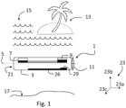
- the autonomous underwater vehicle 1 comprises a hull 3, of cylindrical shape or not. In certain embodiments, the underwater vehicle may be of any other shape.
- This hull extends along a main longitudinal axis 5.
- the main longitudinal axis 5 passes through the nose 21 of the autonomous underwater vehicle 1 and a propulsion system 11, such as propeller thrusters for example.
- Vehicle 1 is shown in the Figure 1 in nominal navigation position, in which the main longitudinal axis 5 is substantially parallel to the horizontal axis.
- horizontal plane is meant a plane having an orientation parallel to the horizon.
- the hull 3 In the nominal navigation position, the hull 3 comprises an upper part 3a facing the sea surface 15, and a lower part 3b facing the seabed 17.
- the vehicle In order to limit as much as possible the effect of drag forces, in general, during nominal navigation of the vehicle (apart from operations requiring maneuvers such as changing orientation), the vehicle is configured to navigate in the nominal position illustrated in Figure 1 , that is to say in which the main longitudinal axis 5 forms a zero or almost zero angle with the horizontal plane.
- the angle formed is an angle between 0° and 10°.
- This angle subsequently called the trim angle, is the longitudinal inclination of the vehicle 1, that is to say the trim angle that the main longitudinal axis 5 forms with the horizontal plane 19 (parallel to the direction 23a of the reference frame 23).
- the underwater vehicle To enable the autonomous underwater vehicle to be maneuvered underwater, the underwater vehicle must neither rise nor fall in its nominal position, meaning that the vehicle must have a zero or near-zero trim angle in the equilibrium position.
- the nominal position of vehicle 1 is an equilibrium position of vehicle 1 when it is submerged, and depends in particular on the relative position of the center of gravity and the center of thrust, also called the center of buoyancy or volume.
- the nominal position of the vehicle, for a vehicle with zero buoyancy is characterized by the fact that the center of gravity and the center of thrust are aligned along the vertical (direction 23b orthogonal to the horizontal plane 19).
- the center of gravity of vehicle 1 depends on its architecture, that is, the mass distribution of its body and the elements it contains inside the hull.
- the center of thrust of the vehicle the place on the vehicle where the hydrostatic forces, "Archimedes' thrust", are applied, varies according to the distribution of volumes in the vehicle.
- the equilibrium position may vary when vehicle 1 is maneuvered, especially when the speed of vehicle 1 is changed, due to the influence of hydrodynamic forces.
- the vehicle 1 therefore includes elements making it possible in particular to manage the relative position of the center of gravity and the center of thrust in order to modify the equilibrium position of the vehicle 1 for carrying out the various maneuvers. In other words, this amounts to modifying the attitude angle of the vehicle 1.
- the underwater vehicle 1 here comprises a thruster 11 arranged at one end of the hull 3 of the vehicle and which is capable of modifying the speed of movement of the vehicle underwater and also of maneuvering the vehicle. Maneuvering the underwater vehicle means allowing its movement in the three directions identified 23a, 23b, 23c by the reference frame 23 represented on the Figure 1 .
- the thrust applied to the vehicle 1 by the thruster 11 then drives the vehicle 1 with the part 21, called the nose, ahead of the rest of the vehicle 1.
- the nose 21 and the thruster 11 are aligned along the main longitudinal axis 5 of the vehicle 1.
- the vehicle 1 comprises adjustment boxes 7, 9 respectively arranged at the front and rear of the vehicle 1. These are boxes 7, 9 defining a volume, partially filled with a liquid, such as water or oil.
- the volume of liquid contained in the adjustment boxes 7, 9 can be modified, so as to vary the center of thrust of the vehicle 1, thus making it possible to vary the trim angle of the vehicle 1.
- the adjustment boxes 7, 9 are connected to each other by a pipe, thus forming a closed circuit.
- control boxes can admit liquid (e.g. sea water) from the outside or discharge liquid to the outside.
- liquid e.g. sea water
- the admission of sea water, to weigh down the control boxes, can be done by means of a tap coupled with a flow limiter (particularly in the event of overpressure outside the vehicle).
- the evacuation of water from the control boxes can be done by means of a pump advantageously coupled with a non-return valve. This variation of the overall volume of liquid in the boxes adjustments allow you to vary the weight of the vehicle in the water. This allows you to move the vehicle closer to or further from the surface.
- the variation of the volume contained in the adjustment boxes 7, 9 makes it possible to modify the position of the center of thrust by modifying the distribution of weight inside the hull 3 of the vehicle.
- These boxes are generally arranged at the front and rear of the vehicle 1.
- the vehicle 1 can include several other adjustment boxes 7, 9, arranged differently (to starboard and to port for example).
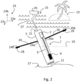
- the thrusters and the adjustment boxes can be used (whatever their positions) to initiate the verticalization of the vehicle 1, as illustrated in Figure 2 .
- FIG. 2 illustrates an example of a surveillance operation of an area of interest 13, requiring the “permanent” vertical positioning of the vehicle 1.
- such a permanent vertical position of the AUV may prove to be interesting, in particular to place the antennas of the AUV out of the water, for example during the phases of recalibration of the navigation system, or communication phases (radio or satellite).
- the initiation of the verticalization of vehicle 1 aims to move vehicle 1 from the nominal position (illustrated in Figure 1 ) to a position close to vertical (illustrated in Figure 2 ): this is done by varying the angle vehicle trim angle, so that the vehicle, balanced in the water, goes from a trim angle of approximately zero to a trim angle of more than 60°.
- the surveillance operation aims to monitor the area of interest 13 by means of a camera 25.
- the camera 25 is arranged on an arm attached to the hull 3 of the vehicle 1.
- the on-board camera 25 is raised above the surface of the water 15 in the direction of the area of interest 13 (by means of an arm 27), and then makes it possible to obtain images of the area of interest 13 whose clarity is satisfactory for the surveillance activities.
- the initiation of the vertical positioning can be done with the adjustment boxes alone, in particular by making the rear of the vehicle 1 heavier than the front of the vehicle.
- the rear adjustment box 9 is entirely filled with liquid
- the front adjustment box 7 is entirely filled with air.
- the initiation of the vertical setting can be carried out by means of the propulsion system, having one of the configurations as presented previously
- the initiation of the vertical positioning makes it possible to obtain a trim angle of the vehicle 1 which is of the order of 70°, so that the main longitudinal axis of the vehicle is not parallel to the vertical direction 23b.
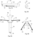
- the autonomous underwater vehicle 30 comprises a verticalization device comprising a single arm 32.
- the arm 32 comprises two ends, a distal end and a proximal end.
- the proximal end is the end of the arm 32 which is rotatably mounted on the hull 40 of the vehicle 30 and the distal end comprises a float 34, that is to say an element whose volume density is lower than that of water.
- the float 34 is integral with the arm 32.
- the arm is able to be arranged in a folded position in which the float 34 is here retracted inside the hull 40 of the vehicle 30. In this folded position, the arm is arranged substantially parallel to the main longitudinal axis 38 of the vehicle 30, so as not to protrude relative to the hull 40 of the vehicle 38, and therefore not to impact the movement of the vehicle 30 (by creating drag forces).
- the arm 32 is rotatably mounted on the shell 40 so as to be at least rotatably movable and to form an angle relative to the longitudinal main axis 38 in the deployed position, as illustrated in Figures 4A and 4B .
- the axis of rotation is an axis orthogonal to the main longitudinal axis 5, and oriented according to the direction 23c of the reference frame 23 reproduced on the Figures 4A and 4B . Rotating the arm 32 from the folded position to the deployed position allows the float 34 to be placed away from the hull 40 of the vehicle 30.
- the buoyancy of the float acts on the position of the center of thrust of the vehicle.
- the float 34 when the arm 32 is in the deployed position, the float 34 is placed at a distance from the hull 40 of the vehicle 30, so that this influences the position of the center of thrust of the vehicle 30.
- the float 34 makes it possible to move a volume of water away from the hull 40 of the vehicle 30, so that the position of the hydrostatic forces applied to the vehicle 30 is modified. causing the modification of the position of the center of thrust.
- the deployment of the arms then makes it possible to act mainly on the position of the center of thrust, by moving it towards the nose 42 of the vehicle 1.
- the vehicle when the arm 32 is deployed, the vehicle can continue its movement towards the vertical and the stability of the vehicle in the vertical position can be improved.
- the characteristics of the arms and floats are chosen so as to allow, when the arm is deployed, to move the center of thrust towards the nose 42.
- the arm 32 is advantageously arranged at the level of the lower hull of the vehicle 30.
- the arm in this example is referred to as a passive arm, because its positioning relative to the main longitudinal axis 38 depends on the characteristics of the float (for example its buoyancy) but also on the length of the arm.
- the arm 32 and the float 34 are configured so that, in the deployed position, the arm 32 is substantially perpendicular to the longitudinal main axis 38 of the autonomous underwater vehicle 30. In certain embodiments, the arm 32, in the deployed position, forms an angle with the longitudinal main axis 38 of the vehicle 1 comprised in the range [80;100].
- the deployment of the arm can be triggered by an actuator or by the initiation of the verticalization movement, as illustrated in the Figures 4A and 3A (arrow 41).
- the arm can be deployed by means of an actuating member allowing the arm to move from a folded position to a deployed position only.
- the arm once deployed, cannot be folded into the folded position, in which the float is retracted into the hull.
- expendable autonomous underwater vehicles which can be used only once at sea.
- the actuating member comprises a spring arranged between the arm 32 and the shell 40 of the vehicle 30 and a switch (of the valve type for example, all or nothing) configured to activate the spring, so that the latter exerts a force on the arm 32 to move it from a folded position, substantially perpendicular to the main axis 38, to a deployed position.
- a switch of the valve type for example, all or nothing
- activate it is meant that the switch is configured to allow the spring to apply a force on the arm 32, so that it comes to take a deployed position.
- the adjustment boxes and/or the propulsion system 36 are controlled to initiate verticalization, and the passive arm 32 is then deployed to have a synergistic action with the adjustment boxes and/or the propulsion 36.
- the arm 32 is then deployed “at the right time” when the initiation of verticalization allows the vehicle to have a trim angle of the order of 70°, making it possible to improve the verticality and the holding of the AUV in a vertical position.
- the deployment of the arms can be done simultaneously or one after the other in a sequence, such as for example starboard then port.
- the vehicle 50 comprises two arms 52, 62 respectively comprising two floats 54, 64 at their distal end.
- the arms are preferably attached to the lower hull, respectively to port and starboard.
- the arms are arranged so as to form an angle 66 included in the range [60°; 180°[.
- the arms 52, 62 are actuable by means of an actuating member allowing one of the arms to move from a folded position to a deployed position and vice versa.
- the actuating member for deploying the arms 52, 62 and vice versa notably comprises a motor, capable of orienting the arms 52, 62 in several angular positions relative to the main longitudinal axis.
- the motorized arms 52, 62 are orientable at least around their axes of rotation (as indicated previously, orthogonal to the main longitudinal axis 58 of the vehicle 50) so as to allow the deployment of the arms 52, 62 in selected deployed positions, for example according to the angle between the main longitudinal axis 58 of the vehicle 50 and the arm 52, 62.
- the actuating member i.e. the motor
- the vehicle 50 may include a verticality sensor, such as one or more accelerometers, so that the angular position of the arm is monitored and controlled according to the output signal of the verticality sensor.
- the float is configured to have a variable volume.
- environmental conditions such as a sudden onset of an unusual swell
- the arm is telescopic, so that the length of the arms can be adjustable.
- the effect of the arms on the center of thrust can be modified by varying the length of the arms.
- the vehicle 50 comprises two active arms 52, 62, it may in one embodiment comprise a single active arm, or more than two active arms.
- the verticalization device comprises, in addition to the active arms, other elements, such as the control boxes and/or the propulsion system 56.
- the arms 52, 62 are deployed after the verticalization is initiated by the control boxes and/or the propulsion system 56.
- the verticalization device is then configured to control the arms 52, 62 and/or the adjustment boxes and/or the propulsion system 56.
- the verticalization device comprises a control unit capable of controlling different elements, in order to ensure the synchronization of their impacts on the center of thrust of the vehicle 80.
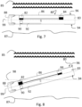
- the vehicle 80 illustrated in these figures is generally cylindrical, is approximately 6.5 m long and has a diameter of approximately 0.5 m. This vehicle 80 has a mass of approximately 1200 kg and when submerged, this vehicle 80 displaces approximately 1100 liters of water.
- the control boxes 82, 84 of the vehicle 80 have a maximum volume of 55 liters respectively. These control boxes 82, 84 are respectively arranged 2m behind and in front of the center of gravity (CDG) and the center of thrust (CDC for center of hull in the figures) which are aligned vertically.
- CDG center of gravity
- CDC center of thrust
- the rear control box 82 is thus arranged between the center of gravity (or thrust) and the propulsion system 88
- the front control box 84 is arranged between the center of gravity (or thrust) and the nose 83 of the vehicle 80.
- the autonomous underwater vehicle 80 comprises adjustment boxes 82, 84 which are arranged, when the vehicle 80 is in nominal position, in an upper part 96 of the hull 86 and the arms are attached to a lower portion 94 of the hull 86 of the vehicle 80.
- the adjustment boxes 82, 84 and the arms 90 are arranged on either side of the longitudinal main axis 99.
- the adjustment boxes are arranged inside the hull of the vehicle 80, in particular in a so-called upper part 96, which, when the vehicle 80 is sailing in the nominal position, is directed towards the surface 85.
- the arms are attached to the lower part 94 of the hull 86, which when the vehicle 80 is sailing in the nominal position, is directed towards the seabed 87.
- the adjustment boxes allow the trim angle of the vehicle 80 to be varied. In this embodiment, only the adjustment boxes allow the trim angle of the vehicle to be varied.
- the figures 7, 8 And 9 illustrate three configurations of the adjustment boxes 82, 84, in which the vehicle 80 respectively has a zero trim angle, a positive trim angle and a negative trim angle, when immersed in sea water (with an estimated mass volume of 1030 kg/m 3 ).
- the adjustment boxes are filled 60% with air at the front and 20% with air at the rear.
- the longitudinal inclination of the vehicle 80 relative to the horizontal plane 98 drives the nose 83 of the vehicle towards the surface of the water 85.
- the filling of the adjustment boxes is modified so that the rear adjustment box 82 has a filling rate greater than the filling rate of the front adjustment box 84.
- the longitudinal inclination of the vehicle 80 relative to the horizontal plane 98 drives the nose 83 of the vehicle towards the bottom 87.
- the filling of the adjustment boxes is modified so that the body of front adjustment 84 has a higher filling rate than the filling rate of the rear adjustment box 82.
- Two arms 92 are rotatably mounted on the hull 86 of the vehicle 80. At the free end of the arm 92, a float 90 is mounted.
- the float has a volume of approximately 10 liters (or 20 liters for the two arms).
- the arms 92 configured to be deployed have a length of approximately 2 m.
- the axis of rotation of the arms is here orthogonal to the main longitudinal axis 99.
- the adjustment boxes 82, 84 are used in conjunction with the arms 92.
- the adjustment boxes are filled with air to 80% at the front and to 0% at the rear 82.
- the rear adjustment box 82 must be completely filled with liquid.
- the adjustment boxes allow a vehicle attitude angle of maximum 75° to be generated.
- the action of the arms, by their deployment, allows regulation of the verticality of the vehicle 80, in a range of +/-12° attitude angle around the vertical (i.e. around a attitude angle of 90°).
- the arms 92a, 92b can be positioned in several isolated positions (some of which are shown in dotted lines on the Figure 10 ).
- the position of the arms is controlled to take one or more isolated positions, when the vehicle initiates a vertical positioning or when the vehicle is in a vertical position, so as to form an angle greater than 0° and less than 180° with the main longitudinal axis of the vehicle 80.
- the deployment of one or both arms in one of the deployed positions as illustrated in the Figure 10 is done according to a method comprising in particular a step in which, when the vehicle's trim angle reaches a first threshold angle, the arm(s) is/are actuated to put them in the deployed position, from the folded position.
- the deployment of the arms of the vehicle 80 can be carried out following a modification of the trim angle of the vehicle, for example by the use of the adjustment boxes 82, 84 and/or the propulsion system, so that this trim angle becomes greater than equal to the first threshold angle.
- the verticalization of the vehicle 80 is initiated prior to the deployment of the arms, and carried out for example by means of the adjustment boxes 82, 84 and/or the propulsion system.
- initializing the vertical setting via the adjustment boxes allows the vehicle 80 to reach a trim angle of approximately 75°.
- the first threshold angle of 70° may be specified, such that the arms are deployed when the vehicle trim angle 80 exceeds 70° via the adjustment boxes.
- the method may also comprise a step of folding the arm(s) of the vehicle 80, when the attitude angle of the vehicle 80 becomes less than a second threshold angle.
- the arms are configured to be actuated and folded, when the trim angle becomes lower than the second threshold value.
Landscapes
- Engineering & Computer Science (AREA)
- Mechanical Engineering (AREA)
- Aviation & Aerospace Engineering (AREA)
- Control Of Position, Course, Altitude, Or Attitude Of Moving Bodies (AREA)
Claims (14)
- Autonomes Unterwasserfahrzeug (1, 30, 50, 80) bestehend aus einer Schale (3, 40, 60, 86), die sich entlang einer Längshauptachse (5, 38, 58, 99) erstreckt, mindestens einer Fahrzeugaufrichtvorrichtung, die so eingerichtet ist, dass sie einen Fahrzeugniveauwinkel (1, 30, 50, 80) zwischen einer horizontalen Nennposition des Fahrzeugs und einer vertikalen Position des Fahrzeugs ändert, wobei die Aufrichtvorrichtung des Fahrzeugs einen oder mehrere Arme (24, 26, 32, 52, 62, 92) umfasst, die durch ein proximales Ende (24a, 26a) an der Schale (3, 40, 60, 86) und drehbar zur Schale (3, 40, 60, 86) angebracht sind, dadurch gekennzeichnet, dass der Arm
einen Schwimmer (28, 29, 34, 54, 64, 90) an einem freien distalen Ende (24b, 26b) umfasst, so dass der Arm (24, 26, 32, 52, 62, 92) zu Folgendem eingerichtet ist:- eine eingeklappte Position, wenn sich das Fahrzeug in Nennposition mit einem Niveauwinkel von nahezu Null befindet, in der der Arm (24, 26, 32, 52, 62, 92) im Wesentlichen parallel zur Längshauptachse (5, 38, 58, 99) des Fahrzeugs (1, 30, 50, 80) liegt und der Schwimmer (28, 29, 34, 54, 64, 90) in unmittelbarer Nähe der Schale (3, 40, 60, 86) liegt;- eine ausgeklappte Position, in der der Arm (24, 26, 32, 52, 62, 92) zur Längshauptachse (5, 38, 58, 99) geneigt ist, um das Fahrzeug (1, 30, 50, 80) in eine sogenannte vertikale Position mit einem Höhenwinkel von mehr als 70° gegenüber seiner Nennposition zu bringen und/oder zu stabilisieren. - Autonomes Unterwasserfahrzeug (1, 50, 80) nach Anspruch 1, umfassend mindestens zwei Arme (24, 26, 52, 62, 92), am Schlepper- und Steuerbordrumpf befestigt, so angeordnet, dass ein Winkel (66) im Bereich von [60° ;180°] entsteht.
- Autonomes Unterwasserfahrzeug (1, 30, 50, 80) nach einem der Ansprüche 1 und 2, umfassend mindestens ein Betätigungselement, das es dem Arm (24, 26, 32, 52, 62, 92) ermöglicht, von der eingeklappten in die ausgeklappte Position zu wechseln.
- Autonomes Unterwasserfahrzeug (50, 80) nach Anspruch 3, wobei das Betätigungselement ferner ermöglicht, dass der Arm (52, 62, 92) von der ausgeklappten in die eingeklappte Position wechselt.
- Autonomes Unterwasserfahrzeug (50, 80) nach Anspruch 4, wobei das Betätigungselement dazu geeignet ist, den Arm (52, 62, 92) in einer bestimmten oder ausgewählten Winkelposition in Bezug auf die Längshauptachse (58, 99) auszurichten.
- Autonomes Unterwasserfahrzeug (50, 80) nach Anspruch 5, wobei das Betätigungselement so eingerichtet ist, dass es die Winkelposition des Arms (52, 62, 92) in der ausgeklappten Position in Bezug auf die Längshauptachse (58, 99) entsprechend dem Neigungswinkel des Fahrzeugs anpasst.
- Autonomes Unterwasserfahrzeug (50, 80) nach einem der Ansprüche 4 und 5, ferner umfassend einen Vertikalsensor, wie beispielsweise einen Beschleunigungsmesser, so dass die Winkelposition des Arms (52, 62, 92) in Abhängigkeit vom Ausgangssignal des Vertikalsensors gesteuert wird.
- Autonomes Unterwasserfahrzeug (1, 30, 50, 80) nach einem der Ansprüche 1 bis 7, wobei der Schwimmer (28, 29, 34, 54, 64, 90) ein variables Volumen aufweist.
- Autonomes Unterwasserfahrzeug (1, 30, 50, 80) nach einem der Ansprüche 1 bis 8, wobei mindestens einer der Arme (24, 26, 32, 52, 62, 92) teleskopierbar ist.
- Autonomes Unterwasserfahrzeug (1, 80) nach einem der Ansprüche 1 bis 9, das eine oder mehrere Einstellkästen (7, 9, 82, 84) und/oder einen oder mehrere Triebwerke umfasst, die in der Lage sind, den Höhenwinkel des Fahrzeugs (1, 80) zu verändern.
- Autonomes Unterwasserfahrzeug (1, 80) nach Anspruch 10, wobei die Einstellkästen (7, 9, 82, 84) angeordnet sind, wenn sich das Fahrzeug (1, 80) in Nennposition befindet, in einem oberen Teil der Schale (3, 86) und die Arme (24, 26, 92) sind an einem unteren Teil der Schale (3, 86) aus dem Fahrzeug (1, 80) entfernen.
- Aufrichtverfahren eines autonomen Unterwasserfahrzeugs (1, 30, 50, 80) nach einem der vorhergehenden Ansprüche, umfassend die Betätigung eines Arms (24, 26, 32, 52, 62, 92), um es aus der eingeklappten Position in die ausgeklappte Position zu bringen, insbesondere wenn der Neigungswinkel des Fahrzeugs (1, 30, 50, 80) einen ersten Schwellenwinkel erreicht.
- Aufrichtverfahren nach den Ansprüchen 10 und 12, das vorab die Einleitung des Aufrichtens des Fahrzeugs (1, 80) über die Einstellkästen (7, 9, 82, 84) oder die Fahrzeugtriebwerke (1, 80) umfasst.
- Verfahren zum Aufrichten nach einem der Ansprüche 12 und 13, das die Betätigung eines Arms (52, 62, 92) umfasst, um ihn aus der ausgeklappten Position in die eingeklappte Position zu bringen, wenn der Höhenwinkel des Fahrzeugs (50, 80) kleiner als ein zweiter Schwellenwinkel ist.
Applications Claiming Priority (2)
| Application Number | Priority Date | Filing Date | Title |
|---|---|---|---|
| FR2106967A FR3124486B1 (fr) | 2021-06-29 | 2021-06-29 | Dispositif de mise à la verticale pour véhicule sous-marin |
| PCT/FR2022/051275 WO2023275476A1 (fr) | 2021-06-29 | 2022-06-28 | Dispositif de mise à la verticale pour véhicule sous-marin |
Publications (2)
| Publication Number | Publication Date |
|---|---|
| EP4363306A1 EP4363306A1 (de) | 2024-05-08 |
| EP4363306B1 true EP4363306B1 (de) | 2025-05-21 |
Family
ID=81327658
Family Applications (1)
| Application Number | Title | Priority Date | Filing Date |
|---|---|---|---|
| EP22744291.0A Active EP4363306B1 (de) | 2021-06-29 | 2022-06-28 | Aufrichtvorrichtung für ein unterwasserfahrzeug |
Country Status (4)
| Country | Link |
|---|---|
| US (1) | US20240294241A1 (de) |
| EP (1) | EP4363306B1 (de) |
| FR (1) | FR3124486B1 (de) |
| WO (1) | WO2023275476A1 (de) |
Families Citing this family (1)
| Publication number | Priority date | Publication date | Assignee | Title |
|---|---|---|---|---|
| CN116812118B (zh) * | 2023-08-30 | 2023-12-22 | 自然资源部第一海洋研究所 | 一种基于保形支撑式的auv海底着陆装置及其方法 |
Family Cites Families (4)
| Publication number | Priority date | Publication date | Assignee | Title |
|---|---|---|---|---|
| JP2006232070A (ja) * | 2005-02-24 | 2006-09-07 | Mitsui Eng & Shipbuild Co Ltd | グライド型水中航走体の姿勢制御方法、無線連絡方法及びグライド型水中航走体 |
| US9487282B2 (en) * | 2014-04-08 | 2016-11-08 | Mrv Systems, Llc | Underwater vehicles configured to perform vertical profiling and diagonal profiling, and corresponding methods of operation |
| US9381987B1 (en) * | 2015-10-01 | 2016-07-05 | Mrv Systems, Llc | Air-based-deployment-compatible underwater vehicle configured to perform vertical profiling and, during information transmission, perform motion stabilization at a water surface, and associated methods |
| CN205916310U (zh) * | 2016-07-06 | 2017-02-01 | 中国船舶重工集团公司第七一九研究所 | 一种深海无人潜航器 |
-
2021
- 2021-06-29 FR FR2106967A patent/FR3124486B1/fr active Active
-
2022
- 2022-06-28 EP EP22744291.0A patent/EP4363306B1/de active Active
- 2022-06-28 WO PCT/FR2022/051275 patent/WO2023275476A1/fr not_active Ceased
- 2022-06-28 US US18/569,644 patent/US20240294241A1/en active Pending
Also Published As
| Publication number | Publication date |
|---|---|
| EP4363306A1 (de) | 2024-05-08 |
| FR3124486A1 (fr) | 2022-12-30 |
| WO2023275476A1 (fr) | 2023-01-05 |
| FR3124486B1 (fr) | 2025-05-23 |
| US20240294241A1 (en) | 2024-09-05 |
Similar Documents
| Publication | Publication Date | Title |
|---|---|---|
| EP3902742B1 (de) | Andockvorrichtung für ein unterwasserfahrzeug | |
| EP1897799B1 (de) | Einrichtung für die dynamische Stabilisierung eines U-Bootes | |
| EP3906188B1 (de) | Andockvorrichtung für ein unterwasserfahrzeug | |
| EP0385827A1 (de) | Antriebsvorrichtung für Unterseeboot | |
| EP3168126B1 (de) | Tragflügel in form eines umgedrehten t, der angepasst ist, um auf einem boot installiert zu werden | |
| FR2709469A1 (fr) | Ensemble de propulsion pour véhicule sous-marin sans équipage. | |
| EP4363306A1 (de) | Aufrichtvorrichtung für ein unterwasserfahrzeug | |
| EP3728020B1 (de) | Verfahren zur steuerung des auftriebs eines unterwasserfahrzeugs | |
| EP0694008B1 (de) | Tragflügelboot mit segeln | |
| EP3728019B1 (de) | Unterwasserfähiges fahrzeug mit einem mast | |
| EP1794049B2 (de) | Vorrichtung zum ablenken von unterwasser- oder schwimmobjekten | |
| EP2353991A2 (de) | Tragfluegelboot | |
| FR2710897A1 (fr) | Véhicule sous-marin autonome utilisant du gaz comprimé comme source d'énergie associé à des surfaces prenant appui sur l'eau. | |
| EP4493456B1 (de) | Geschlepptes unterwasserfahrzeug und system zur bergung solch eines unterwasserfahrzeugs | |
| WO2025125765A1 (fr) | Dispositif de propulsion nautique et navire équipé du dispositif de propulsion | |
| CH721820A2 (fr) | Système de transport à hydroptère | |
| CH720731A2 (fr) | Système de transport à hydroptère comportant au moins un hydroptère | |
| CH720795A2 (fr) | Système de transport à hydroptère à stabilité améliorée | |
| WO2024224248A1 (fr) | Systeme de transport a hydroptere | |
| FR3148213A1 (fr) | Systeme de transport a hydroptere | |
| FR3148779A1 (fr) | Systeme de transport a hydroptere a stabilite amelioree | |
| FR3162201A1 (fr) | Systeme de transport a hydroptere | |
| WO2024236531A1 (fr) | Système de transport à hydroptère à stabilité améliorée | |
| WO1989011997A1 (fr) | Vehicule sous-marin autopropulse pour la detection d'objets immerges | |
| WO2025238609A1 (fr) | Système de transport à hydroptère |
Legal Events
| Date | Code | Title | Description |
|---|---|---|---|
| STAA | Information on the status of an ep patent application or granted ep patent |
Free format text: STATUS: UNKNOWN |
|
| STAA | Information on the status of an ep patent application or granted ep patent |
Free format text: STATUS: THE INTERNATIONAL PUBLICATION HAS BEEN MADE |
|
| PUAI | Public reference made under article 153(3) epc to a published international application that has entered the european phase |
Free format text: ORIGINAL CODE: 0009012 |
|
| STAA | Information on the status of an ep patent application or granted ep patent |
Free format text: STATUS: REQUEST FOR EXAMINATION WAS MADE |
|
| 17P | Request for examination filed |
Effective date: 20231226 |
|
| AK | Designated contracting states |
Kind code of ref document: A1 Designated state(s): AL AT BE BG CH CY CZ DE DK EE ES FI FR GB GR HR HU IE IS IT LI LT LU LV MC MK MT NL NO PL PT RO RS SE SI SK SM TR |
|
| DAV | Request for validation of the european patent (deleted) | ||
| DAX | Request for extension of the european patent (deleted) | ||
| GRAP | Despatch of communication of intention to grant a patent |
Free format text: ORIGINAL CODE: EPIDOSNIGR1 |
|
| STAA | Information on the status of an ep patent application or granted ep patent |
Free format text: STATUS: GRANT OF PATENT IS INTENDED |
|
| INTG | Intention to grant announced |
Effective date: 20250219 |
|
| GRAS | Grant fee paid |
Free format text: ORIGINAL CODE: EPIDOSNIGR3 |
|
| GRAA | (expected) grant |
Free format text: ORIGINAL CODE: 0009210 |
|
| STAA | Information on the status of an ep patent application or granted ep patent |
Free format text: STATUS: THE PATENT HAS BEEN GRANTED |
|
| AK | Designated contracting states |
Kind code of ref document: B1 Designated state(s): AL AT BE BG CH CY CZ DE DK EE ES FI FR GB GR HR HU IE IS IT LI LT LU LV MC MK MT NL NO PL PT RO RS SE SI SK SM TR |
|
| REG | Reference to a national code |
Ref country code: GB Ref legal event code: FG4D Free format text: NOT ENGLISH |
|
| REG | Reference to a national code |
Ref country code: CH Ref legal event code: EP |
|
| REG | Reference to a national code |
Ref country code: DE Ref legal event code: R096 Ref document number: 602022014990 Country of ref document: DE |
|
| REG | Reference to a national code |
Ref country code: IE Ref legal event code: FG4D Free format text: LANGUAGE OF EP DOCUMENT: FRENCH |
|
| PGFP | Annual fee paid to national office [announced via postgrant information from national office to epo] |
Ref country code: DE Payment date: 20250627 Year of fee payment: 4 |
|
| PGFP | Annual fee paid to national office [announced via postgrant information from national office to epo] |
Ref country code: IS Payment date: 20250626 Year of fee payment: 4 Ref country code: NO Payment date: 20250627 Year of fee payment: 4 |
|
| REG | Reference to a national code |
Ref country code: SE Ref legal event code: TRGR |
|
| PGFP | Annual fee paid to national office [announced via postgrant information from national office to epo] |
Ref country code: FR Payment date: 20250527 Year of fee payment: 4 |
|
| PGFP | Annual fee paid to national office [announced via postgrant information from national office to epo] |
Ref country code: AT Payment date: 20250721 Year of fee payment: 4 |
|
| REG | Reference to a national code |
Ref country code: NL Ref legal event code: MP Effective date: 20250521 |
|
| PG25 | Lapsed in a contracting state [announced via postgrant information from national office to epo] |
Ref country code: FI Free format text: LAPSE BECAUSE OF FAILURE TO SUBMIT A TRANSLATION OF THE DESCRIPTION OR TO PAY THE FEE WITHIN THE PRESCRIBED TIME-LIMIT Effective date: 20250521 Ref country code: PT Free format text: LAPSE BECAUSE OF FAILURE TO SUBMIT A TRANSLATION OF THE DESCRIPTION OR TO PAY THE FEE WITHIN THE PRESCRIBED TIME-LIMIT Effective date: 20250922 Ref country code: ES Free format text: LAPSE BECAUSE OF FAILURE TO SUBMIT A TRANSLATION OF THE DESCRIPTION OR TO PAY THE FEE WITHIN THE PRESCRIBED TIME-LIMIT Effective date: 20250521 |
|
| REG | Reference to a national code |
Ref country code: LT Ref legal event code: MG9D |
|
| PG25 | Lapsed in a contracting state [announced via postgrant information from national office to epo] |
Ref country code: GR Free format text: LAPSE BECAUSE OF FAILURE TO SUBMIT A TRANSLATION OF THE DESCRIPTION OR TO PAY THE FEE WITHIN THE PRESCRIBED TIME-LIMIT Effective date: 20250822 |
|
| PG25 | Lapsed in a contracting state [announced via postgrant information from national office to epo] |
Ref country code: PL Free format text: LAPSE BECAUSE OF FAILURE TO SUBMIT A TRANSLATION OF THE DESCRIPTION OR TO PAY THE FEE WITHIN THE PRESCRIBED TIME-LIMIT Effective date: 20250521 Ref country code: NL Free format text: LAPSE BECAUSE OF FAILURE TO SUBMIT A TRANSLATION OF THE DESCRIPTION OR TO PAY THE FEE WITHIN THE PRESCRIBED TIME-LIMIT Effective date: 20250521 |
|
| PGFP | Annual fee paid to national office [announced via postgrant information from national office to epo] |
Ref country code: TR Payment date: 20250716 Year of fee payment: 4 |
|
| PG25 | Lapsed in a contracting state [announced via postgrant information from national office to epo] |
Ref country code: BG Free format text: LAPSE BECAUSE OF FAILURE TO SUBMIT A TRANSLATION OF THE DESCRIPTION OR TO PAY THE FEE WITHIN THE PRESCRIBED TIME-LIMIT Effective date: 20250521 |
|
| PG25 | Lapsed in a contracting state [announced via postgrant information from national office to epo] |
Ref country code: HR Free format text: LAPSE BECAUSE OF FAILURE TO SUBMIT A TRANSLATION OF THE DESCRIPTION OR TO PAY THE FEE WITHIN THE PRESCRIBED TIME-LIMIT Effective date: 20250521 |
|
| PGFP | Annual fee paid to national office [announced via postgrant information from national office to epo] |
Ref country code: SE Payment date: 20250630 Year of fee payment: 4 |
|
| PG25 | Lapsed in a contracting state [announced via postgrant information from national office to epo] |
Ref country code: RS Free format text: LAPSE BECAUSE OF FAILURE TO SUBMIT A TRANSLATION OF THE DESCRIPTION OR TO PAY THE FEE WITHIN THE PRESCRIBED TIME-LIMIT Effective date: 20250821 |
|
| PG25 | Lapsed in a contracting state [announced via postgrant information from national office to epo] |
Ref country code: LV Free format text: LAPSE BECAUSE OF FAILURE TO SUBMIT A TRANSLATION OF THE DESCRIPTION OR TO PAY THE FEE WITHIN THE PRESCRIBED TIME-LIMIT Effective date: 20250521 |
|
| REG | Reference to a national code |
Ref country code: AT Ref legal event code: MK05 Ref document number: 1796545 Country of ref document: AT Kind code of ref document: T Effective date: 20250521 |
|
| PG25 | Lapsed in a contracting state [announced via postgrant information from national office to epo] |
Ref country code: AT Free format text: LAPSE BECAUSE OF FAILURE TO SUBMIT A TRANSLATION OF THE DESCRIPTION OR TO PAY THE FEE WITHIN THE PRESCRIBED TIME-LIMIT Effective date: 20250521 Ref country code: SM Free format text: LAPSE BECAUSE OF FAILURE TO SUBMIT A TRANSLATION OF THE DESCRIPTION OR TO PAY THE FEE WITHIN THE PRESCRIBED TIME-LIMIT Effective date: 20250521 Ref country code: DK Free format text: LAPSE BECAUSE OF FAILURE TO SUBMIT A TRANSLATION OF THE DESCRIPTION OR TO PAY THE FEE WITHIN THE PRESCRIBED TIME-LIMIT Effective date: 20250521 |
|
| PG25 | Lapsed in a contracting state [announced via postgrant information from national office to epo] |
Ref country code: CZ Free format text: LAPSE BECAUSE OF FAILURE TO SUBMIT A TRANSLATION OF THE DESCRIPTION OR TO PAY THE FEE WITHIN THE PRESCRIBED TIME-LIMIT Effective date: 20250521 |
|
| PG25 | Lapsed in a contracting state [announced via postgrant information from national office to epo] |
Ref country code: EE Free format text: LAPSE BECAUSE OF FAILURE TO SUBMIT A TRANSLATION OF THE DESCRIPTION OR TO PAY THE FEE WITHIN THE PRESCRIBED TIME-LIMIT Effective date: 20250521 |
|
| PG25 | Lapsed in a contracting state [announced via postgrant information from national office to epo] |
Ref country code: SK Free format text: LAPSE BECAUSE OF FAILURE TO SUBMIT A TRANSLATION OF THE DESCRIPTION OR TO PAY THE FEE WITHIN THE PRESCRIBED TIME-LIMIT Effective date: 20250521 |
|
| REG | Reference to a national code |
Ref country code: CH Ref legal event code: H13 Free format text: ST27 STATUS EVENT CODE: U-0-0-H10-H13 (AS PROVIDED BY THE NATIONAL OFFICE) Effective date: 20260127 |
|
| PG25 | Lapsed in a contracting state [announced via postgrant information from national office to epo] |
Ref country code: IT Free format text: LAPSE BECAUSE OF FAILURE TO SUBMIT A TRANSLATION OF THE DESCRIPTION OR TO PAY THE FEE WITHIN THE PRESCRIBED TIME-LIMIT Effective date: 20250521 |
|
| PG25 | Lapsed in a contracting state [announced via postgrant information from national office to epo] |
Ref country code: LU Free format text: LAPSE BECAUSE OF NON-PAYMENT OF DUE FEES Effective date: 20250628 |
|
| PG25 | Lapsed in a contracting state [announced via postgrant information from national office to epo] |
Ref country code: MC Free format text: LAPSE BECAUSE OF FAILURE TO SUBMIT A TRANSLATION OF THE DESCRIPTION OR TO PAY THE FEE WITHIN THE PRESCRIBED TIME-LIMIT Effective date: 20250521 |
|
| REG | Reference to a national code |
Ref country code: DE Ref legal event code: R097 Ref document number: 602022014990 Country of ref document: DE |
|
| REG | Reference to a national code |
Ref country code: BE Ref legal event code: MM Effective date: 20250630 |
|
| PG25 | Lapsed in a contracting state [announced via postgrant information from national office to epo] |
Ref country code: RO Free format text: LAPSE BECAUSE OF FAILURE TO SUBMIT A TRANSLATION OF THE DESCRIPTION OR TO PAY THE FEE WITHIN THE PRESCRIBED TIME-LIMIT Effective date: 20250521 |
|
| PLBE | No opposition filed within time limit |
Free format text: ORIGINAL CODE: 0009261 |
|
| STAA | Information on the status of an ep patent application or granted ep patent |
Free format text: STATUS: NO OPPOSITION FILED WITHIN TIME LIMIT |
|
| REG | Reference to a national code |
Ref country code: CH Ref legal event code: L10 Free format text: ST27 STATUS EVENT CODE: U-0-0-L10-L00 (AS PROVIDED BY THE NATIONAL OFFICE) Effective date: 20260402 |
|
| PG25 | Lapsed in a contracting state [announced via postgrant information from national office to epo] |
Ref country code: IE Free format text: LAPSE BECAUSE OF NON-PAYMENT OF DUE FEES Effective date: 20250628 |
|
| PG25 | Lapsed in a contracting state [announced via postgrant information from national office to epo] |
Ref country code: BE Free format text: LAPSE BECAUSE OF NON-PAYMENT OF DUE FEES Effective date: 20250630 |
|
| PG25 | Lapsed in a contracting state [announced via postgrant information from national office to epo] |
Ref country code: CH Free format text: LAPSE BECAUSE OF NON-PAYMENT OF DUE FEES Effective date: 20250630 |
|
| 26N | No opposition filed |
Effective date: 20260224 |