EP4363352B1 - Procédé de stockage ou de récupération d'auxiliaires de stockage - Google Patents
Procédé de stockage ou de récupération d'auxiliaires de stockage Download PDFInfo
- Publication number
- EP4363352B1 EP4363352B1 EP22737716.5A EP22737716A EP4363352B1 EP 4363352 B1 EP4363352 B1 EP 4363352B1 EP 22737716 A EP22737716 A EP 22737716A EP 4363352 B1 EP4363352 B1 EP 4363352B1
- Authority
- EP
- European Patent Office
- Prior art keywords
- shuttle
- storage
- handling device
- shelf
- rack
- Prior art date
- Legal status (The legal status is an assumption and is not a legal conclusion. Google has not performed a legal analysis and makes no representation as to the accuracy of the status listed.)
- Active
Links
Images




Classifications
-
- B—PERFORMING OPERATIONS; TRANSPORTING
- B65—CONVEYING; PACKING; STORING; HANDLING THIN OR FILAMENTARY MATERIAL
- B65G—TRANSPORT OR STORAGE DEVICES, e.g. CONVEYORS FOR LOADING OR TIPPING, SHOP CONVEYOR SYSTEMS OR PNEUMATIC TUBE CONVEYORS
- B65G1/00—Storing articles, individually or in orderly arrangement, in warehouses or magazines
- B65G1/02—Storage devices
- B65G1/04—Storage devices mechanical
- B65G1/0492—Storage devices mechanical with cars adapted to travel in storage aisles
-
- B—PERFORMING OPERATIONS; TRANSPORTING
- B65—CONVEYING; PACKING; STORING; HANDLING THIN OR FILAMENTARY MATERIAL
- B65G—TRANSPORT OR STORAGE DEVICES, e.g. CONVEYORS FOR LOADING OR TIPPING, SHOP CONVEYOR SYSTEMS OR PNEUMATIC TUBE CONVEYORS
- B65G1/00—Storing articles, individually or in orderly arrangement, in warehouses or magazines
- B65G1/02—Storage devices
- B65G1/04—Storage devices mechanical
-
- B—PERFORMING OPERATIONS; TRANSPORTING
- B65—CONVEYING; PACKING; STORING; HANDLING THIN OR FILAMENTARY MATERIAL
- B65G—TRANSPORT OR STORAGE DEVICES, e.g. CONVEYORS FOR LOADING OR TIPPING, SHOP CONVEYOR SYSTEMS OR PNEUMATIC TUBE CONVEYORS
- B65G1/00—Storing articles, individually or in orderly arrangement, in warehouses or magazines
- B65G1/02—Storage devices
- B65G1/04—Storage devices mechanical
- B65G1/0471—Storage devices mechanical with access from beneath
-
- B—PERFORMING OPERATIONS; TRANSPORTING
- B65—CONVEYING; PACKING; STORING; HANDLING THIN OR FILAMENTARY MATERIAL
- B65G—TRANSPORT OR STORAGE DEVICES, e.g. CONVEYORS FOR LOADING OR TIPPING, SHOP CONVEYOR SYSTEMS OR PNEUMATIC TUBE CONVEYORS
- B65G1/00—Storing articles, individually or in orderly arrangement, in warehouses or magazines
- B65G1/02—Storage devices
- B65G1/04—Storage devices mechanical
- B65G1/06—Storage devices mechanical with means for presenting articles for removal at predetermined position or level
- B65G1/065—Storage devices mechanical with means for presenting articles for removal at predetermined position or level with self propelled cars
-
- B—PERFORMING OPERATIONS; TRANSPORTING
- B65—CONVEYING; PACKING; STORING; HANDLING THIN OR FILAMENTARY MATERIAL
- B65G—TRANSPORT OR STORAGE DEVICES, e.g. CONVEYORS FOR LOADING OR TIPPING, SHOP CONVEYOR SYSTEMS OR PNEUMATIC TUBE CONVEYORS
- B65G1/00—Storing articles, individually or in orderly arrangement, in warehouses or magazines
- B65G1/02—Storage devices
- B65G1/04—Storage devices mechanical
- B65G1/137—Storage devices mechanical with arrangements or automatic control means for selecting which articles are to be removed
- B65G1/1373—Storage devices mechanical with arrangements or automatic control means for selecting which articles are to be removed for fulfilling orders in warehouses
- B65G1/1375—Storage devices mechanical with arrangements or automatic control means for selecting which articles are to be removed for fulfilling orders in warehouses the orders being assembled on a commissioning stacker-crane or truck
-
- B—PERFORMING OPERATIONS; TRANSPORTING
- B65—CONVEYING; PACKING; STORING; HANDLING THIN OR FILAMENTARY MATERIAL
- B65G—TRANSPORT OR STORAGE DEVICES, e.g. CONVEYORS FOR LOADING OR TIPPING, SHOP CONVEYOR SYSTEMS OR PNEUMATIC TUBE CONVEYORS
- B65G57/00—Stacking of articles
- B65G57/30—Stacking of articles by adding to the bottom of the stack
- B65G57/301—Stacking of articles by adding to the bottom of the stack by means of reciprocatory or oscillatory lifting and holding or gripping devices
- B65G57/302—Stacking of articles by adding to the bottom of the stack by means of reciprocatory or oscillatory lifting and holding or gripping devices added articles being lifted to substantially stationary grippers or holders
-
- B—PERFORMING OPERATIONS; TRANSPORTING
- B65—CONVEYING; PACKING; STORING; HANDLING THIN OR FILAMENTARY MATERIAL
- B65G—TRANSPORT OR STORAGE DEVICES, e.g. CONVEYORS FOR LOADING OR TIPPING, SHOP CONVEYOR SYSTEMS OR PNEUMATIC TUBE CONVEYORS
- B65G1/00—Storing articles, individually or in orderly arrangement, in warehouses or magazines
- B65G1/02—Storage devices
- B65G1/04—Storage devices mechanical
- B65G1/0407—Storage devices mechanical using stacker cranes
- B65G1/0414—Storage devices mechanical using stacker cranes provided with satellite cars adapted to travel in storage racks
-
- B—PERFORMING OPERATIONS; TRANSPORTING
- B65—CONVEYING; PACKING; STORING; HANDLING THIN OR FILAMENTARY MATERIAL
- B65G—TRANSPORT OR STORAGE DEVICES, e.g. CONVEYORS FOR LOADING OR TIPPING, SHOP CONVEYOR SYSTEMS OR PNEUMATIC TUBE CONVEYORS
- B65G2201/00—Indexing codes relating to handling devices, e.g. conveyors, characterised by the type of product or load being conveyed or handled
- B65G2201/02—Articles
- B65G2201/0235—Containers
Definitions
- the invention relates to a method for storing or retrieving storage aids according to the preamble of claim 1.
- Automated storage systems are known in the field of warehouse logistics for automatically storing and retrieving goods from a warehouse using a storage process. Such storage systems and storage processes are used in modern logistics to enable quick, fast and individual fulfillment of orders. For this purpose, storage systems usually include means for picking goods in order to handle orders that include a large number of different products. However, such storage systems are also used as warehouses, for example in the automotive industry, where, for example, a large number of different components are stored in a common warehouse and must be available at short notice.
- a disadvantage of known storage systems and storage methods is that the storage and retrieval machines that store and retrieve goods move along predetermined paths in the storage system. This results in waiting times when storing and retrieving goods from the storage locations, especially if a storage and retrieval machine has to handle another order beforehand.
- goods can build up, for example when goods are taken over or transferred between the storage system and a conveyor belt.
- the object of the invention is therefore to provide a method for storing or retrieving storage aids with a shuttle in a shelf of an automated storage system, which enables rapid and flexible handling of goods and increases the throughput of goods.
- the method according to the invention is designed for storing or retrieving storage aids with a shuttle in a shelf of an automated storage system.
- the shelf comprises several shelf supports set up on a base and several storage levels arranged vertically one above the other with storage spaces arranged between the shelf supports. Neighboring shelf supports of the shelf that delimit the width of a storage space have a clear width on the base that is smaller than the length of the shuttle in a longitudinal axis of the shuttle and larger than the width of the shuttle in a transverse axis of the shuttle.
- the steps described below are carried out.
- the shuttle is driven under the shelf on the base and the shuttle is coupled to neighboring shelf supports of the shelf.
- the shuttle carries out a vertical climb on these neighboring shelf supports up to the height of the storage level of the storage space in which the storage aid is to be stored or from which the storage aid is to be retrieved.
- the storage aid is then stored from the shuttle into the storage location or the storage aid is removed from the storage location onto the shuttle.
- the method according to the invention comprises the vertical descent of the shuttle along the adjacent shelf supports down to the ground.
- the method also comprises the steps of driving out of the shelf and/or driving in under the shelf on the ground by the shuttle with a direction of travel along the longitudinal axis of the shuttle, as well as turning the shuttle by 90 degrees.
- the method comprises the step of coupling the shuttle by driving up to only two of the adjacent shelf supports, wherein the longitudinal axis of the shuttle is positioned essentially parallel to a shelf front of the shelf.
- the goods throughput in the storage system is significantly increased by the method according to the invention, since a large number of possible access routes are provided for the individual shuttles, which means that the shuttles can easily avoid each other and do not have to wait for other shuttles to pass by.
- the shuttle is positioned in front of the two adjacent shelf supports before being coupled to the two adjacent shelf supports by driving towards the two adjacent shelf supports with a direction of travel along the transverse axis of the shuttle.
- the shuttle is positioned after the shuttle has been rotated and before it is coupled to the two adjacent shelf supports with a journey in the direction of travel of the shuttle's longitudinal axis.
- This also allows the shelf aisles to be used for the shuttle to travel.
- the shuttle moves on the ground in an oncoming traffic area with other shuttles which have a direction of travel essentially opposite to the shuttle. This allows the direction of travel of the individual shuttles to be coordinated with one another and the individual shuttles can move autonomously in the storage system.
- the vertical ascent and/or the vertical descent of the shuttle on the only two adjacent shelf supports is carried out by a friction wheel coupling. This ensures a particularly rapid coupling and decoupling process with a structurally simple and robust coupling mechanism.
- the shuttle preferably has a load-handling device for receiving the storage aid, wherein when the storage aid is stored from the shuttle into the storage location, the load-handling device with the storage aid picked up by the load-handling device is moved from a guide for the load-handling device provided on the shuttle to a guide for the load-handling device provided on the storage location.
- the storage aid is picked up by the load-handling device and the load-handling device with the picked up storage aid is preferably moved from the guide for the load-handling device provided on the storage location to the guide for the load-handling device provided on the shuttle. This ensures that the storage aid is stored and retrieved safely.
- the load-handling device is also preferably controlled by means of a control unit depending on the position of the shuttle in the storage system. This improves the coordination between the load-handling device, storage aid and shuttle.
- the automated storage system in which the method according to the invention is implemented comprises at least one shelf with several shelf supports placed on a base.
- the shelf has several storage levels arranged vertically one above the other, each storage level comprising at least one storage space.
- the storage system also has a number of storage aids that can be stored in the storage locations. Storage aids include, for example, storage containers, storage pallets, trays, boxes and similar devices known in the field of logistics for receiving goods.
- the storage system also includes at least one shuttle with a drive unit, wherein the shuttle is movable on the base by means of the drive unit and which is designed to receive a storage aid and to feed it to and from one of the storage locations.
- the storage system also includes at least one load-carrying device, which is designed to store the storage aid from the shuttle in the storage location and to remove it from the storage location to the shuttle.
- a transfer area is provided between the base and a lowest storage level of the shelf, wherein the transfer area has a height that corresponds at least to a height of a shuttle with a storage aid picked up by the shuttle.
- the shuttle can be moved independently along at least one of the shelf supports by means of the drive unit.
- the design of the automated storage system provides an additional transfer area, which is provided below the lowest storage level. This means that the shuttles can also travel below the lowest storage level, preferably on the ground. This allows for significantly greater flexibility in the possible paths of the shuttles in the storage system than is possible with state-of-the-art storage systems.
- the increased number of possible paths available for a shuttle during the supply or removal of a storage aid from a storage location means that the goods throughput and the speed of the storage system can be increased significantly compared to the state of the art.
- the ability of the shuttle to move along at least one of the shelf supports enables the shuttle to transfer the storage aid from the transfer level to one of the storage levels.
- the shelf supports in the area of the transfer area have a coupling area for receiving the shuttle. This has the advantage that the shuttle can be moved on the ground independently of the shelf supports in the transfer area and can be coupled into the shelf supports at the same time.
- the storage locations each have a guide for guiding the load-handling device. This allows the load-handling device to engage in the guide and position a storage aid on a storage location or remove it from the storage location and transfer it to the shuttle.
- the load-handling device is preferably designed independently of the shuttle. Alternatively The load handling device can also be mechanically and/or electrically coupled to the shuttle.
- the drive unit of the shuttle preferably has at least two drive wheels for moving the shuttle on the ground. This allows the shuttle to perform rotational movements and curved changes of direction on the ground.
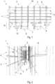
- the automated storage system 1 used in the method according to the invention is shown in an exemplary embodiment in Figure 1 and comprises at least one shelf 2 with several shelf supports 3 set up on a base and running vertically at least in sections.
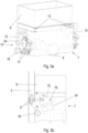
- the storage system 1 comprises several shelves, as in Figure 2
- the shelf 2 has several storage levels 4 arranged vertically one above the other, each storage level 4 comprising at least one storage location 5.
- the storage system 1 comprises several storage aids 6 which can be stored in the storage locations 5.
- the storage system 1 comprises at least one shuttle 7 with a drive unit, the shuttle 7 being movable on the ground by means of the drive unit.
- the drive unit also preferably comprises at least one electric motor.
- the drive unit preferably comprises two drive wheels 8 which serve to move the shuttle 7 on the ground.
- the shelf supports 3 are preferably manufactured by means of a continuous rolling process or a pressing process. Alternative variants of shelf supports 3 are generally known to those skilled in the art.
- the shuttle 7 is designed to receive a storage aid 6 and to feed it to and from one of the storage locations 5.
- the shuttle 7 preferably has a loading area which is in Figure 1 and Figure 3a can be seen.
- the shuttle 7 can also have a receiving space for the storage aid 6, which is designed to receive the storage aid 6.
- the storage system 1 also comprises a load-handling device 9, which is designed to store the storage aid 6 from the shuttle 7 into the storage location 5 and to retrieve it from the storage location 5 onto the shuttle 7.
- the load-handling device 9 is explained in more detail below.
- a transfer area 10 is provided between the base and a lowest storage level 4 of the rack.
- the transfer area 10 has a height which corresponds at least to a height of the shuttle with a storage aid 6 picked up by the shuttle 7. This allows the shuttle 7 to move below the lowest storage level 4 and to drive through the shelf 2.
- the shuttle 7 can be moved along at least one of the shelf supports 3 by means of the drive unit. This allows the shuttle 7 to reach any storage level 4.
- a distance between two adjacent shelf supports 3 is selected such that a shuttle 7 can drive through them.
- the distance is selected such that an axis of the drive wheels 8 of the shuttle 7 is parallel to a distance of two one when the shuttle 7 moves below the lowest storage level 4.
- Storage space 5 is limited by the shelf supports 3.
- the shuttle 7 performs a turn of essentially 90 degrees, so that the axis of the drive wheels 8 is essentially parallel to the course of the shelf, for example normal to a shelf aisle.
- the shelf supports 3 in the area of the transfer area 10 have a coupling area 11 for receiving a shuttle 7.
- the coupling area 11 is in Figure 1 and in Figure 2
- the coupling area 11 is preferably designed as a recess in a profile of the shelf supports 3 in the transfer area 10.
- the drive unit of the shuttle 7 preferably has a shelf support coupling unit 12, wherein the shelf support coupling unit 12 is designed to couple the shuttle to the shelf support 3.
- the shelf support coupling unit 12 is also attached to the shuttles in Figure 1
- the shelf support coupling unit 12 is in the Figures 3a to 3e visible and is described in detail below.
- the shuttle 7 can, for example, engage in this coupling area 11 by means of the shelf support coupling unit 12, whereby the shuttle 7 is coupled to the respective shelf support 3.
- the shelf supports 3 of the storage system 1 preferably do not have any separate mechanisms or devices that enable the shuttle 7 to move along the shelf support 3.
- the shelf support coupling unit 12 is designed to form a frictional connection with the respective shelf support 3 in order to enable force transmission.
- the storage system 1 comprises the load-carrying device 9, which in a preferred embodiment is Figures 4b and 4c
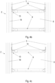
- the storage locations 5, which are in the Figures 4a to 4c preferably each comprise a guide 13 for guiding the load-carrying means 9.
- These guides 13 are designed as a pair of rails in accordance with the embodiment shown in the figures, in which the load-carrying means 9 runs.
- the shuttle 7 has, as shown in Figure 3a
- the load-carrying device 9 also has a guide 13, which is designed as a pair of rails, and into which the load-carrying device 9 can be inserted.
- the load-carrying device 9 preferably has two pairs of running wheels 14, which run in the rails of the guides 13.
- the load-carrying device 9 can thus be easily transferred from the guides 13 in the shelf 2 in the area of the storage locations 5 into the guide 13 of the shuttle 7.
- the load-carrying device 9 is preferably mechanically and/or electrically connected to the shuttle.
- the load-carrying device 9 can, for example, comprise an electric motor as a drive, the load-carrying device 9 being supplied with power by the shuttle 7 by means of a cable connection.
- the load-carrying device 9 can have a have their own battery.
- the load-handling device 9 can comprise a control unit. The control unit is designed to control the load-handling device 9 depending on the position of the shuttle in the storage system 1.
- the load-handling device 9 can be connected to the shuttle 7 by a mechanical drive connection.
- a mechanical drive connection can, for example, comprise a crankshaft, a scissor drive, a chain drive or the like. Further mechanical drive connections will become apparent to the person skilled in the art from this exemplary reference.
- the load-handling device 9 preferably comprises support areas for at least one storage aid 6. If a storage aid 6 is fed from a shuttle 7 to a storage location 5, it is transferred from the shuttle 7 to the respective storage location 5 by means of the load-handling device, or transferred from the storage location 5 to the shuttle 7 when it is removed from storage.
- the load-handling device 9 comprises a lifting mechanism or lifting pneumatics, which enables the storage aid 6 to be lifted so that it rests on the support areas and can be transferred by means of the load-handling device 9.
- the load-handling device 9 can also comprise a gripping mechanism for manipulating the storage aid 6.
- this comprises a chain conveyor, which picks up a storage aid 6, while the load-handling device 9 is pushed under the storage aid 6.
- Figure 4b shows two storage locations 5 arranged one above the other with storage aids 6 stored therein, whereby a load-carrying device 9 is positioned under each of the storage aids 6.
- the respective storage aid 6 is lifted by means of the lifting mechanism of the load-handling device 9, whereby a transfer of the storage aid 6, for example, to a shuttle 7 (not shown) is made possible.
- the load-handling device 9 can also comprise, for example, one or more chain drives and/or one or more belt drives for moving the storage aids 6.
- the chains of the chain drives and/or the belts of the belt drives can also form the support areas.
- the guides 13 of the storage locations 5 are in Figure 4a presented in detail. In Figure 4a It is also clear that any storage depth can be achieved in a storage level 4 of the shelf 2 by means of the load-handling device 9.
- a storage aid 6 can be moved in the shelf 2 along the guides 13, whereby several storage aids 6 can be stored one behind the other in the shelf 2. Furthermore, this construction enables a load-handling device 9 to run through the entire shelf 2 along the guides 13.
- the load-handling devices 9 are designed independently of the shuttles 7 and can move in a storage level 4 independently of the position of a specific shuttle 7. According to this embodiment, the load-handling devices 9 can also, as in Figure 1 shown, remain on shelf 2, while the Shuttles 7 supply and/or remove storage aids 6 to a storage level 4.
- a load-handling device 9 can be transferred from the guides of the shelf 2 into the guide 13 of the shuttle 7 in order to be supplied to another storage level 4 by means of the shuttle 7, for example.
- the shuttles 7 of the storage system 1 each comprise at least one shelf support coupling unit 12, which enables the shuttle 7 to be coupled into or onto a shelf support 3, whereby the shuttle 7 can climb the shelf support 3 and transport a storage aid 6 and/or a load-carrying device 9 to a specific storage level 4.
- connection of the shelf support coupling unit 12 to the shelf support 3 is preferably established by means of a frictional connection, whereby the shelf support 3 can be designed as a simple profile, preferably a rolled profile, and there is no need for additional mechanical components which must be provided on the shelf supports 3 in order to enable a transfer of the shuttles 7 along the shelf supports 3.
- the shuttle 7 with the shelf support coupling unit 12 is shown in detail.
- the shelf support coupling unit 12 comprises a coupling arm 15 on two opposite sides of the shuttle 7.
- Each of the coupling arms 15 is pivotally connected to the shuttle 7 at a pivot point 16. This enables the coupling arms 15 on the shuttle 7 to perform a rotary movement, and the shuttle 7 with any storage aid 6 it may hold to still remain in an upright position.
- a servomotor 24 can also be provided, which acts on the pivot point 16.
- Each of the coupling arms 15 comprises a plurality of rollers, wherein at least some of the rollers rest against the shelf support 3 when the shuttle is coupled to one of the shelf supports 3.
- Figure 3a shows an exemplary version of the Shuttle 7 in a decoupled, and the Figures 3b and 3c show the shuttle 7 in a coupled state to a shelf support 3 or in the course of coupling.
- Figure 3b shows a cross-section through the shelf support, and Figure 3c shows the shelf support 3 in an external view.
- the coupling arm 15 comprises two drive rollers 17 and a guide roller 18.
- the two drive rollers 17 clamp the shelf support 3 at least partially in the course of the coupling process, and are preferably driven by means of a chain drive or a belt drive.
- the chain drive or the belt drive are preferably connected to the drive unit of the shuttle 7.
- the coupling arm 15 also preferably comprises the guide roller 18, which is arranged at a distance from the two drive rollers 17 on the coupling arm 15. At least one of the drive rollers 17 is narrower than the guide roller 18.
- the coupling area 11 is designed as an opening in a side wall of the shelf support 3.
- the shelf support 3 comprises a slot 19, which runs essentially along the entire height of the shelf support 3.
- the slot 19 is narrower than the opening in the coupling area 11, but allows the belt of the belt drive or the chain of the chain drive to be guided from an outer area of the shelf support 3 into the inner area. If the guide roller 18 rests against the shelf support 3, the coupling arm 15 is pivoted in such a way that one of the drive rollers 17 is arranged in the inner area of the shelf support 3, and one of the drive rollers 17 rests against the shelf support 3 from the outside. This state is in Figure 3b visible.
- the design of the shuttle 7 with the shelf support coupling unit 12 also makes it possible to guide the shuttle 7 along a curve or an arc of a support 21.
- the support 21 is preferably designed in the same way as the shelf support 3 described above, with the support 21 additionally comprising an arc or a curve. This is shown in the Figures 5a to 5e visible. Since the shuttle 7 is pivotally connected to the coupling arm 15, the shelf support coupling unit 12 enables the position of the shuttle 7 to be adjusted in relation to the course of the support 21 when traveling through the curve. This makes it possible to guide the support in a curve, with the shuttle 7 automatically performing a position adjustment using a storage aid 6 held by it. As a result, the shuttle 7 maintains an upright orientation, regardless of the course of the support 21.
- the servomotor 24 can also be provided to carry out the position adjustment, which engages the pivot point 16 between the shuttle 7 and the coupling arm 15 and actively pivots the shuttle 7 relative to the coupling arm 15.
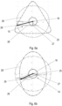
- the pivoting of the shuttle 7 when traveling through the curve of the support 21 is shown in the Figures 5c and 5d
- the servomotor 24 can also change the position of the shuttle 7 at a position of the shuttle 7 on a substantially vertically extending portion of the support 21, as in Figure 5d This enables easy ergonomic removal or insertion of goods into the storage aid 6.
- the guide roller 18 also engages the outer roller guide 23, which is opposite the inner roller guide 22 along the arch, at least in sections. This ensures that the guide roller 18 does not lift off the inner roller guide 22.
- the guide roller 18 thus runs along the curve of the support 21, at least in sections, between the inner roller guide 22 and the outer roller guide 23. This ensures that the drive rollers 17 exert a clamping force on the support, which is oriented normally or at a right angle to the support 21, essentially during the entire passage through the curve of the support 21. This ensures a high frictional force between the support 21 and the drive rollers 17, so that the drive rollers 17 are prevented from slipping on the support 21.
- the coupling arm 15 comprises a joint 27 between the drive rollers 17 and the pivot point 16, as well as a first partial arm 25 and a second partial arm 26.
- a distance between the drive rollers 17 and the pivot point 16 of the coupling arm 16 can be varied, preferably continuously, by means of the joint 27.
- a curve 28 which an engagement point 29 of the drive rollers 17 can follow in relation to the pivot point 16 can be varied by changing the geometry of the coupling arm 15.
- Figure 6a and Figure 6b show two different exemplary curves 29, which the point of attack 29 can follow according to this embodiment.
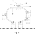
- Figure 5e shows the support 21 with several arches.
- the support 21 in this embodiment comprises several arches as described above, which cause a curvature of the support 21 so that it runs parallel to the ground at least in sections or points.
- the ground is in Figure 5e marked with a dashed line.
- the support 21 can comprise a coupling area 11 in the sections parallel to the ground, or as in Figure 5e shown in the points parallel to the ground. This has the advantage that the shuttle 7 can be easily coupled into the support 21 in the coupling area 11, which is aligned parallel to the ground, and can be uncoupled from it.
- the shuttle can be easily coupled into and out of the support 21 at points parallel to the ground.
- a support 21 with several arches can also be constructed in such a way that different levels above the ground can be reached. Furthermore, this can be used to transfer shuttles 7 between several different grounds that are at different heights. This is particularly useful if the storage system 1 extends over several halls with different zero levels, or to reach different levels of the workstations 20.
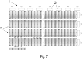
- Figure 7 shows the automated storage system 1 in a schematic view from above with several workstations 20.
- Figure 7 a plurality of shuttles 7 can be seen.
- the shuttles 7 transport storage aids 6 between the workstations 20 and the shelves 2 of the storage system 1.
- each workstation 20 at least one support 21 with a bow according to the Figures 5a to 5e intended.
- the method according to the invention for storing or retrieving storage aids 6 with a shuttle 7 in a shelf 2 of the automated storage system 1 will now be described with reference to Figure 1 explained.
- the shelf 2 has, as already explained, several shelf supports 3 set up on a base and several storage levels 4 arranged vertically one above the other with storage spaces 5 arranged between the shelf supports 3.
- adjacent shelf supports 3 of the shelf 2 delimiting the width of a storage space 5 have a clear width on the base that is smaller than the length of the shuttle 7 in a longitudinal axis of the shuttle 7 and larger than the width of the shuttle 7 in a transverse axis of the shuttle 7.
- the rack 2 is driven under with the shuttle 7 on the ground.
- the method according to the invention comprises coupling the shuttle 7 to adjacent shelf supports 3.
- the first shuttle 7 in the foreground in Figure 1 is shown in this coupling process.
- the method according to the invention comprises a vertical ascent of the shuttle 7 on these adjacent shelf supports 3 up to the height of the storage level 4 of the storage location 5 in which the storage aid 6 is to be stored or from which the storage aid 6 is to be retrieved.
- Shuttle 7 is on the left side of the Figure 1 shown in this vertical ascent.
- the method according to the invention includes storing the storage aid 6 from the shuttle 7 in the storage location 5 or removing the storage aid 6 from the storage location 5 onto the shuttle 7, as well as a vertical descent of the shuttle 7 on the adjacent shelf supports 3 to the ground. Furthermore, the method according to the invention includes driving out of the shelf 2 and/or driving in under the shelf 2 on the ground by the shuttle 7 with a direction of travel along the longitudinal axis of the shuttle 7. This is also in Figure 1 in which the second shuttle 7 enters from the left along its longitudinal axis under the shelf 2. In addition, the method according to the invention includes turning the shuttle 7 by 90 degrees outside the shelf 2.
- the method according to the invention comprises coupling the shuttle 7 by moving it to only two of the adjacent shelf supports 3, whereby the longitudinal axis of the shuttle 7 is positioned essentially parallel to a shelf front of the shelf 2.
- the first shuttle 7 is clearly moving from the right in the foreground towards the only two shelf supports 3.
- the shuttle 7 is positioned in front of the two adjacent shelf supports 3 by approaching the two adjacent shelf supports 3 with a direction of travel along the transverse axis of the shuttle 7 before being coupled to the two adjacent shelf supports 3.
- This achieves the advantage that the shuttle can move directly to the shelf supports and a simple mechanism for coupling to the two adjacent shelf supports can be implemented.
- the shuttle 7 is positioned in front of the two adjacent shelf supports 3 after turning and before coupling to the two adjacent shelf supports 3 by traveling in the direction of travel of the shuttle 7's longitudinal axis. This also allows the shelf aisles to be used for the shuttle 7 to travel. In addition, the shuttles 7 can avoid each other within the shelf aisle or drive past each other.
- the shuttle 7 moves on the ground in a counter-traffic area with other shuttles 7, which have a direction of travel that is essentially opposite to the shuttle 7. This allows the direction of travel of the individual shuttles 7 to be coordinated with one another, and the individual shuttles 7 can move autonomously in the storage system 1.
- the vertical ascent and/or the vertical descent of the shuttle 7 on the only two adjacent shelf supports 3 is carried out by a friction wheel coupling. This ensures a particularly rapid coupling and decoupling process with a structurally simple and robust coupling mechanism.
- the shuttle 7 preferably has a load-handling device 9 for receiving the storage aid 6, wherein when the storage aid 6 is stored from the shuttle 7 into the storage location 5, the load-handling device 9 with the storage aid 6 received by the load-handling device 9 is moved from a guide 13 provided on the shuttle 7 for the load-handling device 9 to a guide 13 provided on the storage location 5 for the load-handling device 9.
- the storage aid 6 is retrieved from the storage location 5 onto the shuttle 7, the storage aid 6 is picked up by the load-handling device 9, and the load-handling device 9 with the picked up storage aid 6 is preferably moved from the guide 13 provided on the storage location 5 for the load-handling device 9 to the guide 13 provided on the shuttle 7 for the load-handling device 9.
- the load-handling device 9 is also preferably controlled by means of a control unit depending on the position of the shuttle 7 in the storage system 1. This improves the coordination between the load-handling device 9, the storage aid 6 and the shuttle 7.
Landscapes
- Engineering & Computer Science (AREA)
- Mechanical Engineering (AREA)
- Warehouses Or Storage Devices (AREA)
Claims (8)
- Procédé de stockage ou de récupération d'auxiliaires de stockage (6) à l'aide d'une navette (7) dans un rayonnage (2) d'un système de stockage automatisé (1), le rayonnage (2) comportant plusieurs montants de rayonnage (3) placés sur un soubassement et plusieurs plans de stockage (4) superposés verticalement avec des emplacements de stockage (5) disposés entre les montants de rayonnage (3), et des montants de rayonnage (3) du rayonnage (2) délimitant la largeur d'un emplacement de stockage (5) au niveau du soubassement présentant une distance libre qui est inférieure à la longueur de la navette (7) dans un axe longitudinal de la navette (7) et supérieure à la largeur de la navette (7) dans un axe transversal de la navette, les étapes suivantes étant exécutées selon ce procédé :passage sous le rayonnage (2) de la navette (7) sur le soubassement,accouplement de la navette (7) à des montants de rayonnage (3) adjacents,montée verticale de la navette (7) sur ces montants de rayonnage (3) adjacents jusqu'à la hauteur du plan de stockage (4) de l'emplacement de stockage (5) dans lequel l'auxiliaire de stockage (6) doit être stocké ou depuis lequel l'auxiliaire de stockage (6) doit être récupéré,stockage de l'auxiliaire de stockage (6) de la navette (7) dans l'emplacement de stockage (5) ou récupération de l'auxiliaire de stockage (6) de l'emplacement de stockage (5) sur la navette (7), descente verticale de la navette (7) sur les montants de rayonnage (3) adjacents jusqu'au soubassement etsortie du rayonnage (2) et/ou entrée sous le rayonnage (2) de la navette (7) sur le soubassement, avec une direction de déplacement le long de l'axe longitudinal de la navette (7),caractérisé en ce que ce procédé comprend les autres étapes suivantes :rotation de la navette (7) à 90 degrés à l'extérieur du rayonnage (2),accouplement de la navette (7) en s'approchant de seulement deux des montants de rayonnage (3) adjacents, l'axe longitudinal de la navette (7) étant positionné sensiblement parallèlement à la face avant du rayonnage (2).
- Procédé selon la revendication 1, caractérisé en ce qu'avant l'accouplement aux seulement deux montants de rayonnage (3) adjacents, la navette (7) se positionne par une approche des seulement deux montants de rayonnage (3) adjacents avec une direction de déplacement le long de l'axe longitudinal de la navette (7).
- Procédé selon une des revendications 1 ou 2, caractérisé en ce qu'après la rotation de la navette et avant l'accouplement aux seulement deux montants de rayonnage (3) adjacents, la navette (7) se positionne devant les seulement deux montants de rayonnage (3) adjacents en se déplaçant dans la direction de l'axe longitudinal de la navette (7).
- Procédé selon une des revendications 1 à 3, caractérisé en ce qu'après le passage sous le rayonnage (2) sur le soubassement, la navette (7) se déplace dans une zone de circulation en sens inverse avec d'autres navettes (7) qui présentent une direction de déplacement sensiblement opposée à la navette (7).
- Procédé selon une des revendications 1 à 4, caractérisé en ce que la montée verticale et/ou la descente verticale de la navette (7) sont exécutées sur les seulement deux montants de rayonnage (3) adjacents par le biais d'un accouplement de roues de fiction.
- Procédé selon une des revendications 1 à 5, caractérisé en ce que la navette (7) comporte un moyen de réception de charge (9) pour recevoir l'auxiliaire de stockage (6), le moyen de réception de charge (9) avec l'auxiliaire de charge (6) réceptionné par le moyen de réception de charge (9) étant, lors du stockage de l'auxiliaire de stockage (6) de la navette (7) dans l'emplacement de stockage (5), déplacés d'un guide (13) prévu pour le moyen de réception de charge (9) sur la navette (7) à un guide (13) prévu pour le moyen de réception de charge (9) sur l'emplacement de stockage (5).
- Procédé selon une des revendications 1 à 6, caractérisé en ce que la navette (7) comporte un moyen de réception de charge (9) pour recevoir l'auxiliaire de stockage (6), l'auxiliaire de stockage (6) étant réceptionné par le moyen de réception de charge (9) lors de la récupération de l'auxiliaire de stockage (6) de l'emplacement de stockage (5) sur la navette (7), et le moyen de réception de charge (9) avec l'auxiliaire de charge (6) réceptionné étant déplacés d'un guide (13) prévu pour le moyen de réception de charge (9) sur l'emplacement de stockage (5) à un guide (13) prévu pour le moyen de réception de charge (9) sur la navette (7).
- Procédé selon une des revendications 6 ou 7, caractérisé en ce que le moyen de réception de charge (9) est commandé au moyen d'une unité de commande en fonction de la position de la navette (7) dans le système de stockage (1).
Applications Claiming Priority (2)
| Application Number | Priority Date | Filing Date | Title |
|---|---|---|---|
| ATA50564/2021A AT525200A1 (de) | 2021-07-08 | 2021-07-08 | Automatisiertes Lagersystem |
| PCT/AT2022/060235 WO2023279127A1 (fr) | 2021-07-08 | 2022-06-30 | Procédé de stockage ou de récupération d'auxiliaires de stockage |
Publications (3)
| Publication Number | Publication Date |
|---|---|
| EP4363352A1 EP4363352A1 (fr) | 2024-05-08 |
| EP4363352B1 true EP4363352B1 (fr) | 2024-10-23 |
| EP4363352C0 EP4363352C0 (fr) | 2024-10-23 |
Family
ID=82404134
Family Applications (2)
| Application Number | Title | Priority Date | Filing Date |
|---|---|---|---|
| EP22737716.5A Active EP4363352B1 (fr) | 2021-07-08 | 2022-06-30 | Procédé de stockage ou de récupération d'auxiliaires de stockage |
| EP22737715.7A Pending EP4367044A1 (fr) | 2021-07-08 | 2022-06-30 | Système de stockage automatisé |
Family Applications After (1)
| Application Number | Title | Priority Date | Filing Date |
|---|---|---|---|
| EP22737715.7A Pending EP4367044A1 (fr) | 2021-07-08 | 2022-06-30 | Système de stockage automatisé |
Country Status (8)
| Country | Link |
|---|---|
| US (2) | US20250100796A1 (fr) |
| EP (2) | EP4363352B1 (fr) |
| CN (2) | CN117642343A (fr) |
| AT (1) | AT525200A1 (fr) |
| CL (2) | CL2024000013A1 (fr) |
| ES (1) | ES3005316T3 (fr) |
| MX (2) | MX2024000411A (fr) |
| WO (2) | WO2023279127A1 (fr) |
Families Citing this family (3)
| Publication number | Priority date | Publication date | Assignee | Title |
|---|---|---|---|---|
| NO347948B1 (en) * | 2022-09-29 | 2024-05-21 | Autostore Tech As | Buffer system |
| AT525735B1 (de) * | 2022-10-06 | 2023-07-15 | Knapp Ag | Automatisiertes Lagersystem mit einem Shuttle zum Transport von Lagerhilfsmitteln |
| DE102023128319A1 (de) * | 2023-10-16 | 2025-04-17 | Hossam Yakub | Automatisiertes Lagersystem |
Family Cites Families (18)
| Publication number | Priority date | Publication date | Assignee | Title |
|---|---|---|---|---|
| US4299496A (en) * | 1978-11-06 | 1981-11-10 | Interlake, Inc. | Load proximity detection techniques |
| US6652213B1 (en) * | 2000-09-08 | 2003-11-25 | California Natural Products | Automated warehousing system and method |
| ITMO20020076A1 (it) * | 2002-03-29 | 2003-09-29 | Ronflette Sa | Magazzino automatico |
| DE102013006391B4 (de) * | 2013-04-12 | 2015-02-26 | Fraunhofer-Gesellschaft zur Förderung der angewandten Forschung e.V. | Bedienfahrzeug, Verfahren zum Bewegen eines Bedienfahrzeugs an einer Lagerregal-Anordnung und Lagerregal-Anordnung |
| DE102013018268B4 (de) * | 2013-10-31 | 2024-02-22 | Sew-Eurodrive Gmbh & Co Kg | Transportsystem |
| US20150225187A1 (en) * | 2014-02-11 | 2015-08-13 | Sergey N. Razumov | Multi-level storage system with transportation devices movable in substantially perpendicular directions and method of transferring containers in desired sequence |
| CN104444007A (zh) * | 2014-07-23 | 2015-03-25 | 贵阳普天物流技术有限公司 | 一种密集式立体仓库货物的存取方法及装置 |
| FR3042182B1 (fr) * | 2015-10-13 | 2020-09-18 | Exotec Solutions | Systeme de preparation de commandes |
| CN108820663A (zh) * | 2018-06-11 | 2018-11-16 | 江苏高科物流科技股份有限公司 | 一种自动化仓储及堆垛机系统 |
| CN108706266B (zh) * | 2018-06-11 | 2021-04-20 | 江苏高科物流科技股份有限公司 | 一种穿梭车式自动化仓储及穿梭车系统 |
| WO2019238697A1 (fr) * | 2018-06-12 | 2019-12-19 | Autostore Technology AS | Système de stockage automatisé |
| DE102018117096A1 (de) * | 2018-07-16 | 2020-01-16 | MBA Instruments GmbH | Transporteinheit für ein Hochregallager |
| CN110356754A (zh) * | 2018-11-06 | 2019-10-22 | 北京京东尚科信息技术有限公司 | 货物拣选系统及方法 |
| CN111731728B (zh) * | 2019-04-30 | 2025-06-13 | 北京京东乾石科技有限公司 | 物品运送系统 |
| US11780676B2 (en) * | 2019-08-14 | 2023-10-10 | Opex Corporation | Systems and methods for managing inventory |
| KR102280791B1 (ko) * | 2019-08-22 | 2021-07-22 | 세창인터내쇼날(주) | 저상형 자동 창고 시스템 |
| CN110723448B (zh) * | 2019-10-21 | 2021-07-09 | 上海快仓智能科技有限公司 | 智能仓储系统及其控制方法 |
| CN112320189B (zh) * | 2020-11-27 | 2024-12-06 | 昆船智能技术股份有限公司 | 一种可垂直攀爬的穿梭车及穿梭车立体仓库 |
-
2021
- 2021-07-08 AT ATA50564/2021A patent/AT525200A1/de not_active Application Discontinuation
-
2022
- 2022-06-30 EP EP22737716.5A patent/EP4363352B1/fr active Active
- 2022-06-30 CN CN202280048567.9A patent/CN117642343A/zh active Pending
- 2022-06-30 MX MX2024000411A patent/MX2024000411A/es unknown
- 2022-06-30 WO PCT/AT2022/060235 patent/WO2023279127A1/fr not_active Ceased
- 2022-06-30 EP EP22737715.7A patent/EP4367044A1/fr active Pending
- 2022-06-30 US US18/576,959 patent/US20250100796A1/en active Pending
- 2022-06-30 ES ES22737716T patent/ES3005316T3/es active Active
- 2022-06-30 CN CN202280048568.3A patent/CN117730040A/zh active Pending
- 2022-06-30 WO PCT/AT2022/060234 patent/WO2023279126A1/fr not_active Ceased
- 2022-06-30 MX MX2024000410A patent/MX2024000410A/es unknown
- 2022-06-30 US US18/576,921 patent/US20240375869A1/en active Pending
-
2024
- 2024-01-03 CL CL2024000013A patent/CL2024000013A1/es unknown
- 2024-01-03 CL CL2024000014A patent/CL2024000014A1/es unknown
Also Published As
| Publication number | Publication date |
|---|---|
| US20240375869A1 (en) | 2024-11-14 |
| AT525200A1 (de) | 2023-01-15 |
| CN117642343A (zh) | 2024-03-01 |
| CN117730040A (zh) | 2024-03-19 |
| KR20240032070A (ko) | 2024-03-08 |
| CL2024000014A1 (es) | 2024-08-09 |
| EP4363352C0 (fr) | 2024-10-23 |
| US20250100796A1 (en) | 2025-03-27 |
| EP4363352A1 (fr) | 2024-05-08 |
| CL2024000013A1 (es) | 2024-06-07 |
| WO2023279126A1 (fr) | 2023-01-12 |
| MX2024000410A (es) | 2024-03-27 |
| ES3005316T3 (en) | 2025-03-14 |
| MX2024000411A (es) | 2024-03-27 |
| EP4367044A1 (fr) | 2024-05-15 |
| WO2023279127A1 (fr) | 2023-01-12 |
| KR20240032074A (ko) | 2024-03-08 |
Similar Documents
| Publication | Publication Date | Title |
|---|---|---|
| EP4363352B1 (fr) | Procédé de stockage ou de récupération d'auxiliaires de stockage | |
| EP2013123B1 (fr) | Module de préparation pour des palettes comprenant un module de transport qui peut être déplacé en-dessous des emplacements d'empilement des palettes, avec un dispositif de levage | |
| AT503427B1 (de) | Verfahren zum ein- und auslagern von ladegut | |
| EP0458021A1 (fr) | Entrepôt avec rayonnages pour matériel recueilli dans des cassettes autoporteuses | |
| EP3475212B1 (fr) | Entrepôt à haut rayonnage comprenant, à l'intérieur, des transstockeurs destinés à stocker et déstocker ou transférer des marchandises entreposées | |
| EP3620422B1 (fr) | Transporteur sans conducteur | |
| EP1695925A1 (fr) | Magasin à rayonnage et procédé pour transférer d'articles dans un magasin à rayonnage | |
| WO2014072265A1 (fr) | Extracteur de marchandise stockée pour un système de stockage automatique | |
| EP3786089A1 (fr) | Dispositif et procédé de transport et de tri des marchandises de détail | |
| EP1446353A1 (fr) | Dispositif servant a deplacer un moyen de suspension de charge en sens transversal dans un systeme en hauteur destine a manipuler des unites de stockage | |
| DE4422240A1 (de) | Verfahren und Einrichtung zur Handhabung von Transportuntersätzen | |
| EP0589844A1 (fr) | Magasin à haute performance avec des moyens pour stocker et prélever des marchandises | |
| EP2746193B1 (fr) | Véhicule pour entrepôt, transstockeur, entrepôt et procédé correspondant | |
| DE3830373A1 (de) | Automatisch arbeitendes lager- und transportsystem zur ver- und entsorgung von arbeitsplaetzen | |
| EP3527507B1 (fr) | Dispositif de préparation de commandes et chariot de préparation de commandes pour un entrepôt à rayonnages | |
| EP3981717A1 (fr) | Véhicule de transport mobile avec une étagère pour recevoir des objets | |
| EP0383257B1 (fr) | Installation d'entrepôt | |
| DE19834927A1 (de) | Verfahren und Vorrichtung zum Ein- und Auslagern von Stückgut | |
| EP1473254B1 (fr) | Système d'entraînement pour dispositif de stockage | |
| DE102016201962B4 (de) | Verfahren und Vorrichtung zur Förderung eines Regallager-Transportfahrzeugs | |
| DE202020104955U1 (de) | Aufzug und Regalsystem | |
| EP4389659A1 (fr) | Dispositif et procédé de préparation de commandes | |
| DE3631602A1 (de) | Regalanordnung | |
| EP0798238B1 (fr) | Système d'entreposage pour palettes pour objets longs | |
| DE19601953C1 (de) | Verfahren und Vorrichtung zum Ein- und Auslagern von Fördergut |
Legal Events
| Date | Code | Title | Description |
|---|---|---|---|
| STAA | Information on the status of an ep patent application or granted ep patent |
Free format text: STATUS: UNKNOWN |
|
| STAA | Information on the status of an ep patent application or granted ep patent |
Free format text: STATUS: THE INTERNATIONAL PUBLICATION HAS BEEN MADE |
|
| PUAI | Public reference made under article 153(3) epc to a published international application that has entered the european phase |
Free format text: ORIGINAL CODE: 0009012 |
|
| STAA | Information on the status of an ep patent application or granted ep patent |
Free format text: STATUS: REQUEST FOR EXAMINATION WAS MADE |
|
| 17P | Request for examination filed |
Effective date: 20240131 |
|
| AK | Designated contracting states |
Kind code of ref document: A1 Designated state(s): AL AT BE BG CH CY CZ DE DK EE ES FI FR GB GR HR HU IE IS IT LI LT LU LV MC MK MT NL NO PL PT RO RS SE SI SK SM TR |
|
| GRAP | Despatch of communication of intention to grant a patent |
Free format text: ORIGINAL CODE: EPIDOSNIGR1 |
|
| STAA | Information on the status of an ep patent application or granted ep patent |
Free format text: STATUS: GRANT OF PATENT IS INTENDED |
|
| DAV | Request for validation of the european patent (deleted) | ||
| DAX | Request for extension of the european patent (deleted) | ||
| INTG | Intention to grant announced |
Effective date: 20240724 |
|
| GRAS | Grant fee paid |
Free format text: ORIGINAL CODE: EPIDOSNIGR3 |
|
| GRAA | (expected) grant |
Free format text: ORIGINAL CODE: 0009210 |
|
| STAA | Information on the status of an ep patent application or granted ep patent |
Free format text: STATUS: THE PATENT HAS BEEN GRANTED |
|
| RIN1 | Information on inventor provided before grant (corrected) |
Inventor name: GAILBERGER, CHRISTOPH Inventor name: PUNTIGAM, WOLFGANG Inventor name: MATHI, FRANZ |
|
| AK | Designated contracting states |
Kind code of ref document: B1 Designated state(s): AL AT BE BG CH CY CZ DE DK EE ES FI FR GB GR HR HU IE IS IT LI LT LU LV MC MK MT NL NO PL PT RO RS SE SI SK SM TR |
|
| REG | Reference to a national code |
Ref country code: GB Ref legal event code: FG4D Free format text: NOT ENGLISH |
|
| RIN1 | Information on inventor provided before grant (corrected) |
Inventor name: GAILBERGER, CHRISTOPH Inventor name: PUNTIGAM, WOLFGANG Inventor name: MATHI, FRANZ |
|
| REG | Reference to a national code |
Ref country code: CH Ref legal event code: EP |
|
| REG | Reference to a national code |
Ref country code: DE Ref legal event code: R096 Ref document number: 502022001977 Country of ref document: DE |
|
| REG | Reference to a national code |
Ref country code: IE Ref legal event code: FG4D Free format text: LANGUAGE OF EP DOCUMENT: GERMAN |
|
| U01 | Request for unitary effect filed |
Effective date: 20241023 |
|
| U07 | Unitary effect registered |
Designated state(s): AT BE BG DE DK EE FI FR IT LT LU LV MT NL PT RO SE SI Effective date: 20241107 |
|
| REG | Reference to a national code |
Ref country code: ES Ref legal event code: FG2A Ref document number: 3005316 Country of ref document: ES Kind code of ref document: T3 Effective date: 20250314 |
|
| PG25 | Lapsed in a contracting state [announced via postgrant information from national office to epo] |
Ref country code: IS Free format text: LAPSE BECAUSE OF FAILURE TO SUBMIT A TRANSLATION OF THE DESCRIPTION OR TO PAY THE FEE WITHIN THE PRESCRIBED TIME-LIMIT Effective date: 20250223 Ref country code: HR Free format text: LAPSE BECAUSE OF FAILURE TO SUBMIT A TRANSLATION OF THE DESCRIPTION OR TO PAY THE FEE WITHIN THE PRESCRIBED TIME-LIMIT Effective date: 20241023 |
|
| PG25 | Lapsed in a contracting state [announced via postgrant information from national office to epo] |
Ref country code: NO Free format text: LAPSE BECAUSE OF FAILURE TO SUBMIT A TRANSLATION OF THE DESCRIPTION OR TO PAY THE FEE WITHIN THE PRESCRIBED TIME-LIMIT Effective date: 20250123 |
|
| PG25 | Lapsed in a contracting state [announced via postgrant information from national office to epo] |
Ref country code: GR Free format text: LAPSE BECAUSE OF FAILURE TO SUBMIT A TRANSLATION OF THE DESCRIPTION OR TO PAY THE FEE WITHIN THE PRESCRIBED TIME-LIMIT Effective date: 20250124 |
|
| PG25 | Lapsed in a contracting state [announced via postgrant information from national office to epo] |
Ref country code: PL Free format text: LAPSE BECAUSE OF FAILURE TO SUBMIT A TRANSLATION OF THE DESCRIPTION OR TO PAY THE FEE WITHIN THE PRESCRIBED TIME-LIMIT Effective date: 20241023 |
|
| PG25 | Lapsed in a contracting state [announced via postgrant information from national office to epo] |
Ref country code: RS Free format text: LAPSE BECAUSE OF FAILURE TO SUBMIT A TRANSLATION OF THE DESCRIPTION OR TO PAY THE FEE WITHIN THE PRESCRIBED TIME-LIMIT Effective date: 20250123 |
|
| PG25 | Lapsed in a contracting state [announced via postgrant information from national office to epo] |
Ref country code: SM Free format text: LAPSE BECAUSE OF FAILURE TO SUBMIT A TRANSLATION OF THE DESCRIPTION OR TO PAY THE FEE WITHIN THE PRESCRIBED TIME-LIMIT Effective date: 20241023 |
|
| U20 | Renewal fee for the european patent with unitary effect paid |
Year of fee payment: 4 Effective date: 20250612 |
|
| PG25 | Lapsed in a contracting state [announced via postgrant information from national office to epo] |
Ref country code: SK Free format text: LAPSE BECAUSE OF FAILURE TO SUBMIT A TRANSLATION OF THE DESCRIPTION OR TO PAY THE FEE WITHIN THE PRESCRIBED TIME-LIMIT Effective date: 20241023 |
|
| PG25 | Lapsed in a contracting state [announced via postgrant information from national office to epo] |
Ref country code: CZ Free format text: LAPSE BECAUSE OF FAILURE TO SUBMIT A TRANSLATION OF THE DESCRIPTION OR TO PAY THE FEE WITHIN THE PRESCRIBED TIME-LIMIT Effective date: 20241023 |
|
| PLBE | No opposition filed within time limit |
Free format text: ORIGINAL CODE: 0009261 |
|
| STAA | Information on the status of an ep patent application or granted ep patent |
Free format text: STATUS: NO OPPOSITION FILED WITHIN TIME LIMIT |
|
| 26N | No opposition filed |
Effective date: 20250724 |
|
| PGFP | Annual fee paid to national office [announced via postgrant information from national office to epo] |
Ref country code: ES Payment date: 20250707 Year of fee payment: 4 |
|
| PGFP | Annual fee paid to national office [announced via postgrant information from national office to epo] |
Ref country code: CH Payment date: 20250717 Year of fee payment: 4 |
|
| PG25 | Lapsed in a contracting state [announced via postgrant information from national office to epo] |
Ref country code: MC Free format text: LAPSE BECAUSE OF FAILURE TO SUBMIT A TRANSLATION OF THE DESCRIPTION OR TO PAY THE FEE WITHIN THE PRESCRIBED TIME-LIMIT Effective date: 20241023 |
|
| PG25 | Lapsed in a contracting state [announced via postgrant information from national office to epo] |
Ref country code: IE Free format text: LAPSE BECAUSE OF NON-PAYMENT OF DUE FEES Effective date: 20250630 |