EP4389659A1 - Dispositif et procédé de préparation de commandes - Google Patents
Dispositif et procédé de préparation de commandes Download PDFInfo
- Publication number
- EP4389659A1 EP4389659A1 EP23215784.2A EP23215784A EP4389659A1 EP 4389659 A1 EP4389659 A1 EP 4389659A1 EP 23215784 A EP23215784 A EP 23215784A EP 4389659 A1 EP4389659 A1 EP 4389659A1
- Authority
- EP
- European Patent Office
- Prior art keywords
- pallet
- picking
- shaft
- order
- section
- Prior art date
- Legal status (The legal status is an assumption and is not a legal conclusion. Google has not performed a legal analysis and makes no representation as to the accuracy of the status listed.)
- Pending
Links
Images






Classifications
-
- B—PERFORMING OPERATIONS; TRANSPORTING
- B65—CONVEYING; PACKING; STORING; HANDLING THIN OR FILAMENTARY MATERIAL
- B65G—TRANSPORT OR STORAGE DEVICES, e.g. CONVEYORS FOR LOADING OR TIPPING, SHOP CONVEYOR SYSTEMS OR PNEUMATIC TUBE CONVEYORS
- B65G57/00—Stacking of articles
- B65G57/02—Stacking of articles by adding to the top of the stack
- B65G57/03—Stacking of articles by adding to the top of the stack from above
- B65G57/035—Stacking of articles by adding to the top of the stack from above with a stepwise downward movement of the stack
-
- B—PERFORMING OPERATIONS; TRANSPORTING
- B65—CONVEYING; PACKING; STORING; HANDLING THIN OR FILAMENTARY MATERIAL
- B65G—TRANSPORT OR STORAGE DEVICES, e.g. CONVEYORS FOR LOADING OR TIPPING, SHOP CONVEYOR SYSTEMS OR PNEUMATIC TUBE CONVEYORS
- B65G1/00—Storing articles, individually or in orderly arrangement, in warehouses or magazines
- B65G1/02—Storage devices
- B65G1/04—Storage devices mechanical
- B65G1/137—Storage devices mechanical with arrangements or automatic control means for selecting which articles are to be removed
- B65G1/1373—Storage devices mechanical with arrangements or automatic control means for selecting which articles are to be removed for fulfilling orders in warehouses
- B65G1/1378—Storage devices mechanical with arrangements or automatic control means for selecting which articles are to be removed for fulfilling orders in warehouses the orders being assembled on fixed commissioning areas remote from the storage areas
-
- G—PHYSICS
- G06—COMPUTING OR CALCULATING; COUNTING
- G06Q—INFORMATION AND COMMUNICATION TECHNOLOGY [ICT] SPECIALLY ADAPTED FOR ADMINISTRATIVE, COMMERCIAL, FINANCIAL, MANAGERIAL OR SUPERVISORY PURPOSES; SYSTEMS OR METHODS SPECIALLY ADAPTED FOR ADMINISTRATIVE, COMMERCIAL, FINANCIAL, MANAGERIAL OR SUPERVISORY PURPOSES, NOT OTHERWISE PROVIDED FOR
- G06Q10/00—Administration; Management
- G06Q10/08—Logistics, e.g. warehousing, loading or distribution; Inventory or stock management
- G06Q10/087—Inventory or stock management, e.g. order filling, procurement or balancing against orders
-
- B—PERFORMING OPERATIONS; TRANSPORTING
- B65—CONVEYING; PACKING; STORING; HANDLING THIN OR FILAMENTARY MATERIAL
- B65G—TRANSPORT OR STORAGE DEVICES, e.g. CONVEYORS FOR LOADING OR TIPPING, SHOP CONVEYOR SYSTEMS OR PNEUMATIC TUBE CONVEYORS
- B65G2201/00—Indexing codes relating to handling devices, e.g. conveyors, characterised by the type of product or load being conveyed or handled
- B65G2201/02—Articles
- B65G2201/0267—Pallets
Definitions
- the invention relates to a device for order picking on pallets or goods carriers with an order picking shaft, with a pallet buffer for unloaded pallets, wherein the pallet buffer is arranged laterally next to the order picking shaft and with a feed device for transporting an unloaded pallet from the order picking shaft to the pallet buffer or from the pallet buffer to the order picking shaft.
- the invention also relates to a method for order picking.
- the invention aims to improve a device and method for order picking on pallets or goods carriers with regard to the flexibility of their use.
- a device for order picking on pallets or goods carriers with the features of claim 1 is provided for this purpose.
- a method for order picking on pallets or goods carriers with the features of claim 10 is provided.
- the pallet buffer has at least two storage spaces for pallets or goods carriers of different sizes. This means that pallets or goods carriers of different sizes can be loaded selectively and directly one after the other using the picking device. This is because the pallet buffer is used to store an unloaded pallet outside the picking shaft. to temporarily store them in order to arrange them at the height of the picking level immediately after a fully loaded pallet has been lowered into the picking shaft.
- the picking device according to the invention can therefore be used in an extremely flexible manner.
- the at least two storage locations in the pallet buffer are arranged one above the other in the height direction of the picking shaft.
- a lifting and lowering device is provided in order to move an unloaded pallet up to the height of the pallet buffer.
- An unloaded pallet can thus be stored in a storage location in the pallet buffer while a pallet is being loaded.
- the picking shaft has at least one first adjustable shaft wall, wherein by means of the first adjustable shaft wall a free cross section of the picking shaft can be changed at least in sections by means of a movement of the first adjustable shaft wall perpendicular to the height direction of the picking shaft, wherein the first adjustable shaft wall has an upper section and a lower section in the height direction of the picking shaft, wherein the upper section extends from a height position of the pallet buffer to a picking level at the upper end of the picking shaft, wherein the lower section extends downwards starting from the height position of the pallet buffer and wherein the upper section and the lower section are adjustable independently of one another.
- the free cross-section of the picking shaft can be adjusted so that the walls of the picking shaft only are arranged at a very short distance from the side edges of the pallet that is currently being loaded. This prevents loads that are positioned on the pallet from falling into the picking shaft next to the pallet. This is extremely advantageous when picking is to be carried out on pallets of different sizes. This is because a picker and/or a picking robot do not have to be extremely careful to position the load exactly on the edge of the pallet.
- the first adjustable shaft wall has an upper section and a lower section that can be adjusted independently of one another, it is possible to simultaneously load a first pallet of a first size with goods and to drive a second pallet of a different size into the picking shaft from below and then place it in the pallet buffer.
- the pallet to be placed in the pallet buffer is not loaded, so there is no risk of goods falling off the pallet.
- a first pallet of a small size is loaded, an unloaded pallet of a small size is usually always placed in the pallet buffer, so that two pallets of different sizes are always arranged in the pallet buffer.
- a picker or master computer then always has the choice of whether a large or small pallet should be loaded next.
- the device according to the invention does not cause any waiting signals.
- the upper section and the lower section of the first adjustable shaft wall can be arranged immediately adjacent to the load on the pallet as the pallet is loaded and then gradually lowered in order to prevent load on the pallet from slipping or even falling off during the progressive lowering.
- the upper section of the adjustable shaft wall is connected to a section of the picking level.
- an edge between the horizontally arranged picking level and the vertically arranged first adjustable shaft wall is moved when the first shaft wall is adjusted.
- an order picker or an order picking robot always has an edge or a stop available in the area of the first adjustable shaft wall to arrange loads quickly and precisely on the pallet to be loaded or on loads that have already been stacked.
- a second shaft wall is provided which is adjustable at least in sections, wherein the second adjustable shaft wall is perpendicular to the first adjustable shaft wall and wherein by means of the second adjustable shaft wall a free cross-section of the picking shaft can be changed at least in sections by means of a movement of the second adjustable shaft wall perpendicular to the height direction of the picking shaft.
- a third shaft wall is provided which is adjustable at least in sections, wherein the third adjustable shaft wall is arranged perpendicular to the first adjustable shaft wall and wherein by means of the third adjustable shaft wall a free cross section of the picking shaft can be changed at least in sections by means of a movement of the third adjustable shaft wall perpendicular to the height direction of the picking shaft.
- one adjustable shaft wall is sufficient to adjust the free cross-section of the picking shaft to the size of the pallet that is currently being loaded. If, on the other hand, the cross-section of the different pallets is not identical, it may be advantageous to adjust three shaft walls of the picking shaft to process the two pallets of different sizes. This can be the case, for example, if the pallets are always to be arranged with their center of gravity in the middle of the free cross-section of the picking shaft, or if the feet of the pallets are positioned in such a way that the distance from the feet of the different pallets to the shaft walls of the picking shaft changes between different pallets. A first, second and third adjustable shaft wall can then be used to ensure that all four shaft walls of the picking shaft are arranged directly adjacent to the edges of the pallet loading area.
- means are provided for holding and moving a pallet in the upper section of the picking shaft between a height position of the pallet buffer and an upper end of the picking shaft, wherein the means for holding and moving are designed and arranged to take an unloaded pallet from the pallet buffer from the feed device, to move the unloaded pallet to the upper end of the picking shaft and, during the start of the loading process, to lower the pallet step by step until the pallet is transferred from the means for holding and moving to a lifting and lowering device, wherein the means for holding and moving have a plurality of pallet supports which can be moved into and out of a free cross-section of the picking shaft and wherein the pallet supports can be moved into and out of the free cross-section of the picking shaft below a standing area for a picker or a picking robot.
- an unloaded pallet can be moved from the height of the pallet buffer to the upper end of the picking shaft, i.e. until the loading surface of the pallet is approximately at the level of or just below the picking level.
- These holding and moving means are independent of a lifting and lowering device that takes unloaded pallets from a feeding conveyor, enters the picking shaft from below and then transfers them to the feeding device of the pallet buffer.
- the lifting and lowering device also takes partially loaded pallets from the holding and moving means in order to either lower them step by step during further loading or to move fully loaded pallets downwards in the picking shaft in order to then be able to strap these fully loaded pallets or wrap them in stretch film, for example.
- the lifting and lowering device is also designed to then transfer the fully loaded and finished pallets back to a discharging conveyor.
- the interaction of the lifting and lowering device on the one hand and the means for holding and moving on the other hand makes it possible to take an unloaded pallet from the pallet buffer and arrange it at the height of or just below the height of the picking level while a fully loaded pallet is being transported away or strapped or wrapped in order to be able to continue picking without losing time.
- the means for holding and moving have several pallet supports that can be moved into and out of a free cross-section of the picking shaft, whereby the pallet supports can be moved into and out of the free cross-section of the picking shaft below a standing area for an order picker or an order picking robot
- three walls of the picking shaft can be made very narrow in the transverse direction, for example. The insides of these walls form the shaft walls of the picking shaft. This enables very good ergonomics, as an order picker can stand very close to the items to be loaded. Pallet can stand and in particular does not have to bend over a very wide wall of the picking shaft in order to move loads onto the pallet loading area.
- the pallet supports are therefore moved below a standing area of the picking platform into the free cross-section of the picking shaft and also moved out of the free cross-section of the picking shaft again below the standing area of the picking platform.
- the pallet supports Above the standing area of the picking platform, the pallet supports are always arranged in such a way that they protrude into the free cross-section of the picking shaft and can therefore only be moved vertically above the standing area of the picking platform, i.e. towards the picking level and away from the picking level.
- the pallet supports can, for example, be swivelled into the free cross-section of the picking shaft and then moved up and down again using a suitable height adjustment. There is sufficient space available beneath the base of the picking platform to easily move the pallet supports out of the free cross-section of the picking shaft, for example by swiveling them out or by means of a sliding movement or along a curved path.
- the pallet supports above the standing area for an order picker or an order picking robot can only be moved in and against the height direction of the order picking shaft.
- the problem underlying the invention is also solved by a method for order picking on pallets or goods carriers with a device according to the invention.
- the method according to the invention provides, among other things, that while a pallet is being loaded, another unloaded pallet is brought into the picking shaft from below and then moved into one of the storage locations of the pallet buffer by means of the feed device. Depending on which pallet size is to be loaded next, a pallet of this size is brought into the picking shaft by means of the feed device from one of the storage locations of the pallet buffer and moved upwards to the picking level by the means for holding and moving. While the pallet is being loaded, the pallet is then gradually lowered downwards by the means for holding and moving, in accordance with the height of the load already stacked on the pallet.
- the shaft walls of the picking shaft takes place independently of one another in an upper section and a lower section of the first adjustable shaft wall. This means, for example, that a small pallet can already be loaded and a large pallet can be lowered downwards through the picking shaft.
- the unloaded pallets are conveniently stored in the pallet buffer one above the other so that pallets of different sizes can be moved directly from their respective storage locations into the picking shaft without first having to be re-sorted or rearranged in the pallet buffer.
- pallet supports of the means for holding and moving are pivoted into the free cross-section of the picking shaft below a standing area for an order picker or order picking robot on the order picking platform and then moved to move an unloaded pallet upwards to the order picking level and subsequently when lowering a pallet step by step, exclusively in the vertical direction or against the vertical direction of the order picking shaft.
- at least one, and possibly several walls of the order picking shaft can be narrow when viewed transversely to the vertical direction, resulting in very good ergonomics for an order picker. Because at least one boundary wall of the order picking shaft is very narrow, the order picker does not have to bend far over this wall, but can move the load onto the pallet with a short and quick movement close to the body.
- Fig.1 shows a device 10 according to the invention for order picking.
- the device 10 is designed as a manual order picking station and one or more order pickers 12 move load 14, which is delivered by means of a conveyor system 16 shown only schematically, onto an initially unloaded pallet.
- the device 10 stands on a hall floor 6 on which the conveyor system 56 is also arranged.
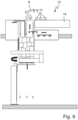
- Fig.9 an automatic picking station.
- the device 10 has, when designed as an automatic picking station according to Fig.9 a picking robot 8 which, like the picker 12 at the manual picking station, takes load 14 from the conveyor system 16 and moves it onto an initially unloaded pallet.
- the device 10 designed as a manual picking station of the Fig.1 and the device 10 designed as an automatic picking station of the Fig.9 but identically constructed.
- the device 10 for a mixed operation, in which both an order picker 12 and a Order picking robots 8 are provided to jointly load an initially unloaded pallet with load 14.
- the device 10 of the Fig.1 has a picking platform 18, the upper side 20 of which forms a standing area for one or two order pickers 12.
- a picking shaft 22 extends through the picking platform 18.
- An upper end of the picking shaft 22 forms part of a picking level 24.
- Fig.1 is a schematic representation that allows a view into the picking shaft 22 from the side. For this reason, only three shaft walls of the picking shaft 22 are visible, namely a first adjustable shaft wall 26, a second adjustable shaft wall 28 and a third, fixed shaft wall 30. A third adjustable shaft wall is arranged opposite and parallel to the second adjustable shaft wall 28, but as explained, in Fig.1 is not shown.
- the first adjustable shaft wall 26 has an upper section 26a and a lower section 26b.
- the upper section 26a and the lower section 26b have been adjusted in different ways. This will be explained below.
- Both the upper section 26a and the lower section 26b of the first adjustable shaft wall 26 can be adjusted in and against an arrow 28, i.e. perpendicular to a height direction of the picking shaft 22.
- a pallet buffer 30 is provided, which Fig.1 is also only shown schematically, but has two storage spaces for pallets of different sizes. These two storage spaces are in the embodiment of the Fig.1 arranged one above the other.
- a first, smaller pallet 32 has just been partially moved from an upper storage location of the pallet buffer 30 in a horizontal direction into the free cross section of the order picking shaft 22 by means of a feed device (not shown).
- a second, larger pallet 36 is arranged in a second, lower storage location of the pallet buffer 30.
- the first pallet 32 is still empty and therefore not loaded.
- the second pallet 36 is also empty and not loaded.
- the two storage locations of the pallet buffer 30 are intended exclusively for unloaded, empty pallets 32, 36.
- the first, smaller pallet 32 is already partially located in the free cross-section of the picking shaft 22.
- the pallet 32 is taken over there by means 38 for holding and moving and can then be moved upwards in the height direction of the picking shaft 22 up to the picking level 24 according to the arrow 40.
- the first pallet 32 is moved upwards by means of the means 38 for holding and moving until an upper side of the first pallet 32 is at the level of the picking level 24 or just below the picking level 24.
- the means 38 for holding and moving move the pallet 32 step by step downwards according to its loading state, i.e. against the arrow 40.
- the order picker 12 can thus always arrange the load 14 approximately at the level of the picking level 24.
- a third pallet 42 is already fully loaded and is arranged below the height position of the pallet buffer 30.
- the third pallet 42 is already arranged below the lower end of the picking shaft 22, whereby this lower end of the picking shaft 22 is defined by a wrapping device 44.
- the fully loaded pallet 42 is currently being wrapped with stretch film 46.
- the fully or partially loaded pallet 42 is lowered downwards according to the arrow 48. This is done by means of a lifting and lowering device 50.
- Load 14 is stacked in several layers on the third pallet 42. While the lowest stack of load 14, which lies directly on the loading surface of the third pallet 42, is being wrapped using stretch film 46, the upper layers of load 14 are still located within the lower section 26b of the picking shaft 22. This ensures that the load 14 cannot fall off the third pallet 42.
- FIG.1 It is in Fig.1 It can be seen that the lower section 26b of the first adjustable shaft wall 26 is arranged directly adjacent to the upper layers of load 14 on the third pallet 42.
- the upper section 26a of the first adjustable shaft wall 26, on the other hand, has been moved a little way into the free cross-section of the picking shaft 22.
- the first adjustable shaft wall 26 has thus already been adjusted with its upper section 26a to the size of the first, smaller pallet 32, whereas the lower section 26b is still adjusted to the dimensions of the large pallet 42 or the stack of load 14 on the pallet 42.
- the second adjustable shaft wall 28 and the opposite, not visible third adjustable shaft wall have also already been adjusted a little in order to be able to accommodate the first, smaller pallet 32.
- the second adjustable shaft wall 28 and the opposite third adjustable shaft wall are adjusted so that the distance between the second adjustable shaft wall and the third adjustable shaft wall increases. This is to accommodate the first, smaller pallet 32, which is in a direction perpendicular to the plane of the Fig.1 longer than the large second pallet 36 and the large third pallet 42.
- the order picker 12 On the condition of the Fig.1 follows the state of Fig.2 the device 10.
- the order picker 12 is in Fig.2 no longer shown for reasons of clarity.
- the order picker 12 has already arranged a first layer of load 14 on the first, smaller pallet 32.
- the first pallet 32 can now be lowered a little with the help of the means 38 for holding and moving, which in the state of Fig.2 has already happened.
- the top of the load stacked on the pallet 32 is therefore already approximately at the height of the order picking level 24 and the order picker 12 can stack further load 14, which is delivered by means of the conveyor system 16, on the first layer of load 14.
- the upper section 26a of the first adjustable shaft wall 26 is arranged unchanged so that it is arranged adjacent to the lateral boundary of the pallet 32.
- the lower section 26b of the first adjustable shaft wall was adjusted compared to the state of the Fig.1 according to the arrow 52 into the free cross-section of the picking shaft 22.
- the lower section 26b is aligned in the state of Fig.2 with the upper section 26a of the first adjustable shaft wall 26.
- the lower section 26b can be in the state of Fig.2 into the free cross-section of the picking shaft 22, since the large third pallet 42 has already been completely wrapped with stretch film 46 and has been moved downwards according to the arrow 54 by means of the lifting and lowering device 50. Neither the third pallet 42 nor the stack of load on the third pallet 42 is therefore still within the picking shaft 22.
- the lifting and lowering device 50 transfers the fully loaded pallet 42 to a conveyor system 56, which is only shown schematically and which ensures the removal of the fully loaded third pallet 42.
- the second pallet 36 is in the state of Fig. 2 unchanged in its storage location in the palette buffer 30.
- Fig.3 In the state of Fig.3 was the Fig.2 The fully loaded third pallet 42 shown here was removed and is therefore no longer shown.
- a unloaded fourth pallet 58 is delivered and already taken over by the lifting and lowering device 50.
- the fourth pallet 58 In the state of the Fig.3 the fourth pallet 58 is already transported upwards towards the lower end of the picking shaft 22.
- the order picker 12 loads the first pallet 32 with the load 14, which is transported via the conveyor device 16.
- the first pallet 32 was lowered step by step according to its loading state.
- the order picker 12 stacks another layer of load 14 on the then top layer of load on the first pallet 32, the latter is lowered by the means for holding and moving 38 until the top side of the top layer of load is then at or slightly below the height of the order picking level 24.
- the first pallet 32 was lowered a little, as just described, so that another layer of load 14 can be stacked.
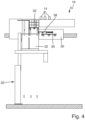
- the lifting and lowering device 50 has brought the fourth pallet 58 into the picking shaft 22 from below at the level of the pallet buffer 30.
- the feed device (not shown) takes over the fourth pallet 58 and moves it out of the free cross-section of the picking shaft 22 to the first storage location of the pallet buffer 30. This movement takes place according to the schematic representation of the Fig.4 to the right.
- a small pallet and a large pallet namely the fourth pallet 58 and the second pallet 36, are again available in the pallet buffer 30 in an unloaded state.
- Fig.5 shows you the condition of the Fig.4 following state of the device 10.
- the first pallet 32 has been fully loaded and is in the state of Fig.5 already from the Fig.5
- the lifting and lowering device 50 has been transferred to the lifting and lowering device 50 by means of non-recognizable means for holding and moving.
- the lifting and lowering device 50 has in the state of Fig.5 the fully loaded pallet 32 has already been lowered so far that it is located just before the end of the picking shaft 22.
- the upper section 26a and the lower section 26b of the first adjustable shaft wall 26 are in the state of Fig.5 unchanged in a position adjacent to the side edge of the first pallet 32 or adjacent to the stack of load 14 on the first pallet 32. This prevents load 14 on the pallet 32 from falling sideways into the picking shaft 32.
- the first pallet 32 has already been lowered by means of the lifting and lowering device 50 so far that the stack of loads on the first pallet 32 can be wrapped with stretch film 46 in the wrapping station 44.
- the 14 uppermost layers of the stack of loads 14 on the first pallet 32 are still held laterally by the lower section 26b of the first adjustable shaft wall and by the other shaft walls of the picking shaft 22.
- the uppermost layer of loads 14 on the first pallet 32 is already arranged below the height position of the pallet buffer 30.
- the large second unloaded pallet 36 can now be removed from the pallet buffer 30 by means of the feed device (not shown) and transferred to the means for holding and moving 38.
- the small fourth unloaded pallet 58 could be removed from the pallet buffer 30 and transferred to the holding and moving means 38.
- the upper section 26a of the first adjustable shaft wall 26 has been moved out of the free cross-section of the picking shaft 22 in a direction according to the arrow 25, in Fig.6 i.e. to the left, in order to adapt the free cross-section of the picking shaft 22 to the dimensions of the second, larger pallet 36.
- the second, larger pallet 36 is already loaded with cargo 14 by the order picker 12 (not shown) and gradually lowered by the means for holding and moving 38 according to the number of layers on the pallet 36.
- the means for holding and moving 38 lower the second pallet 36 by the height of one layer of load 14 so that the order picker can stack further load 14.
- the second storage location in the pallet buffer 30 is empty and only the small fourth pallet 58 is located in the pallet buffer 30.
- the first, fully loaded and wrapped pallet 32 is in the state of Fig.7 just transferred from the lifting and lowering device 50 to the conveyor system 56.
- the cross-section of the picking shaft 22 below the second pallet 36 is free, so that the latter can be lowered further step by step, transferred to the lifting and lowering device 50 and then wrapped with stretch film.
- either the fourth pallet 58 or the fifth pallet 60 can be removed from the pallet buffer 30 and placed in the picking shaft 22 in order to then load either the fourth, small pallet 58 or the fifth, large pallet 60.
- the decision as to whether a small pallet or a large pallet is loaded is made by a process computer (not shown), which also ensures that the load 14 intended for the respective pallet is delivered via the conveyor system 16.
- pallets of different sizes can also be loaded directly one after the other.
- the device 10 according to the invention can therefore be used in an extremely flexible manner.
- Fig.9 shows, as already explained, the device 10 according to a second embodiment.
- the device 10 is provided with an order picking robot 8, which takes over the load 14 from the conveyor system 16 and positions it on a pallet provided in the order picking shaft 22.
- an order picker 12 can also work alongside the order picking robot 8.
- the device 10 is operated with the order picking robot 8 in the same way as with the Fig. 1 to 8 has already been described.
- Fig.10 shows a schematic plan view of the device 10.
- Two order pickers 12a, 12b are shown schematically and are intended to be Fig.10 to take over the not shown load from the conveyor system 16 and move it onto a pallet 32, the top or loading surface of which is arranged at the height of the picking level.
- the smaller, first palette 32 is shown.
- the first adjustable shaft wall 26 has been moved into the free cross-section of the picking shaft 22 and is now immediately adjacent to the Fig.10 left side edge of the pallet 32.
- a fourth, fixed shaft wall 70 is arranged, which is also immediately adjacent to the Fig.10 right side edge of the pallet 32.
- the second adjustable shaft wall 28 can be seen, which has been moved a little way out of the free cross-section of the picking shaft 22.
- the second adjustable shaft wall is in the state of Fig.10 also directly adjacent to the Fig.10 upper edge of the pallet 32.
- the third adjustable shaft wall 72 can now be seen, which is located opposite the second adjustable shaft wall 28.
- the third adjustable shaft wall has also been moved a little out of the free cross-section of the picking shaft 22 and is now directly adjacent to the Fig.10 lower edge of the pallet 32.
- the free cross-section of the picking shaft 22 has thus been adjusted to the size of the loading area of the pallet 32 at the height of the picking level, so that there is only a narrow circumferential gap between the outer contour of the loading area of the small pallet 32 and the shaft walls 26, 28, 70, 72.
- the order pickers 12a, 12b can now take over load from the conveyor 16 and place it on the pallet 32. Since the shaft walls 26, 28, 70 and 72 of the order picking shaft 22 are arranged directly adjacent to the edges of the pallet 32, there is no fear of load falling off the pallet 32 and into the order picking shaft 32. The order pickers 12 can even press load against one of the shaft walls 26, 28, 70, 72 and use this as a stop when placing load.
- Fig.10 The means 38 for holding and moving the pallet 32 are shown schematically.
- the means 38 have a total of six pallet supports 74a, 74b, 74c, 74d, 74e and 74f.
- the pallet supports 74 would not be recognizable as such, since they are arranged under the pallet 32, but for clarity they are shown in Fig.10 marked.
- the pallet 32 rests with four of its feet on the pallet supports 74b, 74c, 74e and 74f.
- the pallet supports 74b, 74c, 74e, 74f would in and of themselves be in the top view of the Fig.10 cannot be seen, since they are arranged below the pallet 32.
- the pallet supports 74a, 74d are in the state of Fig.10 not used and would not be recognizable in and of themselves, since they are arranged below a section 76 which is arranged horizontally and which is connected to the first adjustable shaft wall 26.
- the pallet supports 74a to 74f in an upper section of the picking shaft 22, which extends from the base 20 of the picking platform 18 to the picking level 24, can only be moved in and against the height direction of the picking shaft 22. Only below the base 20 of the picking platform 18 can the pallet supports 74a to 74f be pivoted or moved out of the free cross-section of the picking shaft 22, which will be described below.
- Fig. 11 shows another schematic plan view of the device 10.
- a second, larger pallet 36 is now arranged in the picking shaft 22.
- the first adjustable shaft wall 26 was moved out of the free cross-section of the picking shaft 22 at least in the area of its upper section 26a.
- the upper section 26a of the first adjustable shaft wall 26 is immediately adjacent to the Fig. 11 left side edge of the pallet 36.
- the fourth fixed shaft wall 70 is also located immediately adjacent to the Fig. 11 right side edge of the pallet 36.
- the free cross-section of the picking shaft 22 has thus been adjusted to the size of the loading area of the pallet 36 at the height of the picking level, so that there is only a narrow circumferential gap between the outer contour of the large pallet 36 and the shaft walls 26, 28, 70, 72.
- the pallet 36 rests with six of its feet on each of the pallet supports 74a to 74f.
- pallets with four feet, cross boards instead of feet or a surrounding frame instead of feet can also be loaded and moved.
- only the shape and/or arrangement of the pallet supports must be adapted.
- the pallet supports 74a to 74f are in the top view of the Fig. 11 cannot be recognized in and of themselves, since they are arranged below the pallet 36, and have only been shown for clarification. In and of themselves, the pallet supports 74a to 74f would be visible in the top view of the Fig. 11 covered by the pallet 36.
- Fig. 11 the pallet buffer 30 is shown, which is also not visible in the top view. Specifically, a small, fourth pallet 58 and a large, fifth pallet 60 are shown. The fourth, small pallet 58 is located in the first storage location of the pallet buffer 30, which is arranged above the second storage location in the pallet buffer 30, with the fifth, large pallet 60 being located in the second storage location.
- the small pallets 58 and the large pallets 36, 60 do not have identical transverse dimensions.
- the small pallet 58 is narrower than the large pallet 60, but longer.
- the picking on the small pallets 58 and the large pallets 36, 60 is made possible by the device 10 according to the invention in that the picking shaft 22 is delimited by three adjustable shaft walls 26, 28, 72 and only one fixed shaft wall 70.
- Fig. 12 shows a schematic sectional view of the device 10 of Fig.1 .
- the cutting plane in Fig. 12 runs parallel to the height direction of the picking shaft 22, whereby the representation of the Fig. 12 is schematic.
- Fig. 12 serves to illustrate the means for moving and holding 38 and shows how the pallet supports 74a to 74f of the means 38 for holding and moving are moved into or out of the free cross-section of the picking shaft 22.
- Fig. 12 the picking platform 18 can be seen, the upper side of which is the base 20 for the Fig. 12 order pickers 12a, 12b shown only in the area of their feet.
- Fig. 12 It can be seen that the pallet supports 74a to 74f, whereby in Fig. 12 only two pallet supports 74c and 74f are shown in different states of movement, can be moved out of the free cross-section of the picking shaft 22 below the base 20.
- the pallet supports 74 are pivoted out along a curved path, for example, or pivoted or tilted about a rotation axis. In order to be able to carry out such a movement, a comparatively large amount of space is required to the side of the relevant shaft wall of the picking shaft 22. This space is available below the base 22 and in Fig. 12 For this purpose, a cavity 88a, 88b is schematically shown under the base 20
- the pallet supports 74a to 74f can only be moved in and against the height direction of the picking shaft 22. This can be seen from the different positions of the two pallet supports 74c and 74f in Fig. 12 Only after the pallet supports 74a to 74f are arranged again below the base 20 can they be swiveled, tilted or moved away in order to free up the cross-section of the picking shaft 22 again.
- the pallet supports 74a to 74f are guided in sliding guides, for example, and are moved using suitable drive technology.
- Fig. 12 thus shows several chronologically successive states simultaneously in order to illustrate how the two pallet supports 74c, 74f are first moved into the free cross-section of the picking shaft 22 and then moved upwards to the upper end of the picking shaft 22.
- the walls 78a and 78b of the picking shaft 22 can be made very narrow.
- the two order pickers 12a, 12b therefore do not have to bend far over the upper limit of these two walls 78a, 78b in order to move loads onto a pallet arranged in the picking shaft 22.
- Fig. 13 shows a schematic sectional view of the device 10, wherein the cutting plane runs parallel to the height direction of the picking shaft 22.
- the cutting plane in Fig. 13 but is perpendicular to the cutting plane of the Fig. 12
- the presentation of the Fig. 13 schematically.
- the picking platform 18 and the pallet buffer 30 can be seen.
- the first storage space in the pallet buffer 30 is occupied by a large pallet 36.
- This large pallet 36 is arranged in a holder 80 of the feed device.
- This holder can be moved horizontally, in Fig. 13 i.e. to the left, into the picking shaft 22 and back again.
- the holder 80 holds the feet of the pallet 36.
- the second storage space in the pallet buffer 30 is occupied by a small pallet 32.
- the pallet 32 is arranged in a second holder 82 of the feed device.
- the second holder 82 can be moved together with the pallet 32 in a horizontal direction to the left, into the picking shaft 22 and back again. In the state of Fig. 13 the second holder 82 has already been moved a little way into the picking shaft 22.
- the second holder 82 is moved further to the left into the picking shaft 22 until the feet of the pallet 32 are arranged above the pallet supports 74.
- the pallet 32 can then be placed on the pallet supports 74 and the second holder 82 can be pulled back again so that it is moved out of the free cross-section of the picking shaft 22.
- the pallet supports 74 lift the pallet 32 a little so that the holder 82 is released from the pallet 32 and can be moved back into the pallet storage 30.
- Fig. 13 is shown schematically.
- Fig. 13 thus illustrates several consecutive states simultaneously in order to clarify the movement sequence.
- the large pallet 36 would be moved in the same way by means of the first holder 80 into the free cross-section of the picking shaft 22 and placed there with its feet on the pallet supports 74.
- the pallet 36 can then be moved in the picking shaft 22 in the direction of the upper end of the picking shaft 32, which in Fig. 13 is shown schematically.
- FIG. 13 The upper section 26a of the first adjustable shaft wall and the lower section 26b of the first adjustable shaft wall 26 are shown.
- the upper section 26a is in the state of Fig. 13 into the free cross-section of the picking shaft 22, thereby reducing the free cross-section of the picking shaft 22 to the Adjust the size of the loading area of the small pallet 32 so that there is only a narrow gap at the sides of the small pallet 32.
- the lower section 26b is shown in a retracted position, so that at the level of the lower section 26b a large pallet 36 can be moved in the picking shaft 22 and, for example, introduced into the pallet buffer 30, cf. the illustrations of the Fig.8 and 9 .
- Fig. 13 shows vertically arranged guides 86 for the pallet supports 74.
- the pallet supports 74 can be moved in and against the height direction of the picking shaft 22.
- openings 84 are shown in the shaft wall of the picking shaft 22. Through these openings 84, the pallet supports 74 can be moved out of the free cross section of the picking shaft 22, for example, swung out.
- the small pallet 32 is removed from the pallet buffer 30 and moved upwards to just below the height of the picking level 24 to be loaded there.
- the second storage space in the pallet buffer 30 is then empty.
- a small pallet is then placed back into the pallet buffer 30 to fill the empty storage space and so that there is always a large pallet and a small pallet in the pallet buffer 30.
- either a large pallet or a small pallet is then removed from the pallet buffer and brought upwards to the height of the picking level 24 for loading.
- pallets to be loaded are always removed from the pallet buffer 30.
- the device 30 it is also possible with the device 30 to lift an unloaded pallet by means of the lifting and lowering device 50 and to transfer it directly to the means 38 for holding and moving and then to move it to the height of the picking level 24 for loading.
Landscapes
- Engineering & Computer Science (AREA)
- Business, Economics & Management (AREA)
- Mechanical Engineering (AREA)
- Economics (AREA)
- Marketing (AREA)
- Strategic Management (AREA)
- Entrepreneurship & Innovation (AREA)
- Human Resources & Organizations (AREA)
- Finance (AREA)
- Operations Research (AREA)
- Quality & Reliability (AREA)
- Development Economics (AREA)
- Tourism & Hospitality (AREA)
- Physics & Mathematics (AREA)
- General Business, Economics & Management (AREA)
- General Physics & Mathematics (AREA)
- Theoretical Computer Science (AREA)
- Accounting & Taxation (AREA)
- Warehouses Or Storage Devices (AREA)
Applications Claiming Priority (1)
| Application Number | Priority Date | Filing Date | Title |
|---|---|---|---|
| DE102022213844.9A DE102022213844B4 (de) | 2022-12-19 | 2022-12-19 | Vorrichtung zum Kommissionieren |
Publications (1)
| Publication Number | Publication Date |
|---|---|
| EP4389659A1 true EP4389659A1 (fr) | 2024-06-26 |
Family
ID=89190465
Family Applications (1)
| Application Number | Title | Priority Date | Filing Date |
|---|---|---|---|
| EP23215784.2A Pending EP4389659A1 (fr) | 2022-12-19 | 2023-12-12 | Dispositif et procédé de préparation de commandes |
Country Status (3)
| Country | Link |
|---|---|
| US (1) | US20240199335A1 (fr) |
| EP (1) | EP4389659A1 (fr) |
| DE (1) | DE102022213844B4 (fr) |
Cited By (1)
| Publication number | Priority date | Publication date | Assignee | Title |
|---|---|---|---|---|
| AT527587B1 (de) * | 2023-12-29 | 2025-04-15 | Tgw Logistics Group Gmbh | Wickelvorrichtung und Wickelverfahren zum Umwickeln von auf einem Ladungsträger angeordneten Produkten mit zumindest einer Folie |
Families Citing this family (1)
| Publication number | Priority date | Publication date | Assignee | Title |
|---|---|---|---|---|
| JP2025183703A (ja) * | 2024-06-05 | 2025-12-17 | 株式会社ダイフク | 物品積付設備 |
Citations (3)
| Publication number | Priority date | Publication date | Assignee | Title |
|---|---|---|---|---|
| WO2009109218A1 (fr) * | 2008-03-04 | 2009-09-11 | Dematic Ltd. | Procédé et poste de travail pour empilement multicouche semi-automatique sur un support de charge |
| DE202016001581U1 (de) * | 2016-03-07 | 2017-06-08 | Winkel Gmbh | Vorrichtung zum Kommissionieren auf Paletten |
| DE102014220046B4 (de) | 2014-10-02 | 2017-11-30 | Winkel Gmbh | Vorrichtung zum Kommissionieren auf Paletten |
Family Cites Families (5)
| Publication number | Priority date | Publication date | Assignee | Title |
|---|---|---|---|---|
| GB1560714A (en) * | 1978-01-27 | 1980-02-06 | Nordic Saunas Ltd | Shower cabinet |
| EP1930119B1 (fr) * | 2006-12-08 | 2014-08-20 | Trumpf Sachsen GmbH | Installation mécanique pour le traitement de pièces |
| US20090022572A1 (en) * | 2007-07-19 | 2009-01-22 | Thomas Pass | Cluster tool with a linear source |
| EP3272682B1 (fr) * | 2016-07-22 | 2019-06-26 | Ulma Manutencion, S. Coop. | Dispositif de manipulation de palettes, appareil de palettisation et procédé de manipulation de palettes |
| DE102020205722B4 (de) * | 2020-05-06 | 2025-10-23 | Winkel Gmbh | Vorrichtung und Verfahren zum Kommissionieren auf oder von Warenträgern |
-
2022
- 2022-12-19 DE DE102022213844.9A patent/DE102022213844B4/de active Active
-
2023
- 2023-12-12 EP EP23215784.2A patent/EP4389659A1/fr active Pending
- 2023-12-19 US US18/544,931 patent/US20240199335A1/en active Pending
Patent Citations (3)
| Publication number | Priority date | Publication date | Assignee | Title |
|---|---|---|---|---|
| WO2009109218A1 (fr) * | 2008-03-04 | 2009-09-11 | Dematic Ltd. | Procédé et poste de travail pour empilement multicouche semi-automatique sur un support de charge |
| DE102014220046B4 (de) | 2014-10-02 | 2017-11-30 | Winkel Gmbh | Vorrichtung zum Kommissionieren auf Paletten |
| DE202016001581U1 (de) * | 2016-03-07 | 2017-06-08 | Winkel Gmbh | Vorrichtung zum Kommissionieren auf Paletten |
Cited By (2)
| Publication number | Priority date | Publication date | Assignee | Title |
|---|---|---|---|---|
| AT527587B1 (de) * | 2023-12-29 | 2025-04-15 | Tgw Logistics Group Gmbh | Wickelvorrichtung und Wickelverfahren zum Umwickeln von auf einem Ladungsträger angeordneten Produkten mit zumindest einer Folie |
| AT527587A4 (de) * | 2023-12-29 | 2025-04-15 | Tgw Logistics Group Gmbh | Wickelvorrichtung und Wickelverfahren zum Umwickeln von auf einem Ladungsträger angeordneten Produkten mit zumindest einer Folie |
Also Published As
| Publication number | Publication date |
|---|---|
| DE102022213844A1 (de) | 2024-06-20 |
| US20240199335A1 (en) | 2024-06-20 |
| DE102022213844B4 (de) | 2025-05-15 |
Similar Documents
| Publication | Publication Date | Title |
|---|---|---|
| EP2013123B1 (fr) | Module de préparation pour des palettes comprenant un module de transport qui peut être déplacé en-dessous des emplacements d'empilement des palettes, avec un dispositif de levage | |
| EP2848561B1 (fr) | Procédé et dispositif de déplacement horizontal d'emplacements d'articles entre des modules voisins | |
| EP2648997B1 (fr) | Moyen de réception de charge universel pour la manutention sans palette de produits à emmagasiner | |
| EP2128047B2 (fr) | Dispositif de réception pour un véhicule transporteur | |
| DE4217079A1 (de) | Einrichtung zur selektiven palettisierung von gegenstaenden mit unterschiedlichen eigenschaften | |
| WO2013004695A1 (fr) | Système et procédé d'entrée d'un produit à stocker dans un rayon et de sortie hors du rayon | |
| WO2020182699A1 (fr) | Appareil de commande de rayonnages servant au chargement de marchandises empilables et système logistique équipé d'un appareil de commande de rayonnages de ce type | |
| DE2537279A1 (de) | Palettenentlader | |
| DE102022213844B4 (de) | Vorrichtung zum Kommissionieren | |
| DE202016001581U1 (de) | Vorrichtung zum Kommissionieren auf Paletten | |
| EP4363352B1 (fr) | Procédé de stockage ou de récupération d'auxiliaires de stockage | |
| EP0291083B1 (fr) | Procédé et installation pour transférer des plates-formes de transport sur une table élévatrice d'un station d'empilage | |
| EP2199229A2 (fr) | Moyen de réception de charge pour un appareil de commande de rayonnage, installation de transport dotée d'un appareil de commande de rayonnage et procédé de fonctionnement de l'installation de transport | |
| EP2452900B1 (fr) | Station de chargement de chariots-cages, système de commissionnement avec une telle station et procédés correspondants | |
| EP1157947B1 (fr) | Convoyeur vertical | |
| EP4337574B1 (fr) | Dispositif de tri | |
| EP2093166A1 (fr) | Procedé pour le déstockage rapide des articles d'un magasin de stockage et un magasin de stockage correspondant | |
| DE3402996A1 (de) | Anlage zum ein- und auslagern von containern unter verwendung eines hochregallagers | |
| EP3841045B1 (fr) | Dispositif de palettisation et procédé pour faire fonctionner un dispositif de palettisation | |
| DE19915023A1 (de) | Werkstückhandhabungssystem sowie Verfahren zum Handhaben von Werkstücken | |
| EP0798238A2 (fr) | Système d'entreposage pour palettes pour objets longs | |
| EP0436507A1 (fr) | Dispositif pour manutentionner des palettes | |
| DE10305095A1 (de) | Vorrichtung und Verfahren zum Wechseln von Paletten in einem Palettierautomaten | |
| DE3816448C2 (fr) | ||
| AT398745B (de) | Einrichtung zum sortieren von unterschiedlichen, auf buntaufteilanlagen aus plattenförmigen werkstücken durch längs- und querschnitte gewonnene formatzuschnitte |
Legal Events
| Date | Code | Title | Description |
|---|---|---|---|
| PUAI | Public reference made under article 153(3) epc to a published international application that has entered the european phase |
Free format text: ORIGINAL CODE: 0009012 |
|
| STAA | Information on the status of an ep patent application or granted ep patent |
Free format text: STATUS: THE APPLICATION HAS BEEN PUBLISHED |
|
| AK | Designated contracting states |
Kind code of ref document: A1 Designated state(s): AL AT BE BG CH CY CZ DE DK EE ES FI FR GB GR HR HU IE IS IT LI LT LU LV MC ME MK MT NL NO PL PT RO RS SE SI SK SM TR |
|
| STAA | Information on the status of an ep patent application or granted ep patent |
Free format text: STATUS: REQUEST FOR EXAMINATION WAS MADE |
|
| 17P | Request for examination filed |
Effective date: 20241125 |
|
| RBV | Designated contracting states (corrected) |
Designated state(s): AL AT BE BG CH CY CZ DE DK EE ES FI FR GB GR HR HU IE IS IT LI LT LU LV MC ME MK MT NL NO PL PT RO RS SE SI SK SM TR |