EP4364536B1 - Elektrisch leitfähige elastomere drucktinte für kontaktlose druckverfahren - Google Patents
Elektrisch leitfähige elastomere drucktinte für kontaktlose druckverfahren Download PDFInfo
- Publication number
- EP4364536B1 EP4364536B1 EP21790901.9A EP21790901A EP4364536B1 EP 4364536 B1 EP4364536 B1 EP 4364536B1 EP 21790901 A EP21790901 A EP 21790901A EP 4364536 B1 EP4364536 B1 EP 4364536B1
- Authority
- EP
- European Patent Office
- Prior art keywords
- printing ink
- electrically conductive
- printing
- silicone elastomer
- elastomer composition
- Prior art date
- Legal status (The legal status is an assumption and is not a legal conclusion. Google has not performed a legal analysis and makes no representation as to the accuracy of the status listed.)
- Active
Links
Classifications
-
- C—CHEMISTRY; METALLURGY
- C08—ORGANIC MACROMOLECULAR COMPOUNDS; THEIR PREPARATION OR CHEMICAL WORKING-UP; COMPOSITIONS BASED THEREON
- C08J—WORKING-UP; GENERAL PROCESSES OF COMPOUNDING; AFTER-TREATMENT NOT COVERED BY SUBCLASSES C08B, C08C, C08F, C08G or C08H
- C08J3/00—Processes of treating or compounding macromolecular substances
- C08J3/02—Making solutions, dispersions, lattices or gels by other methods than by solution, emulsion or suspension polymerisation techniques
-
- C—CHEMISTRY; METALLURGY
- C08—ORGANIC MACROMOLECULAR COMPOUNDS; THEIR PREPARATION OR CHEMICAL WORKING-UP; COMPOSITIONS BASED THEREON
- C08J—WORKING-UP; GENERAL PROCESSES OF COMPOUNDING; AFTER-TREATMENT NOT COVERED BY SUBCLASSES C08B, C08C, C08F, C08G or C08H
- C08J3/00—Processes of treating or compounding macromolecular substances
- C08J3/20—Compounding polymers with additives, e.g. colouring
- C08J3/203—Solid polymers with solid and/or liquid additives
-
- C—CHEMISTRY; METALLURGY
- C08—ORGANIC MACROMOLECULAR COMPOUNDS; THEIR PREPARATION OR CHEMICAL WORKING-UP; COMPOSITIONS BASED THEREON
- C08K—Use of inorganic or non-macromolecular organic substances as compounding ingredients
- C08K3/00—Use of inorganic substances as compounding ingredients
- C08K3/02—Elements
- C08K3/04—Carbon
-
- C—CHEMISTRY; METALLURGY
- C08—ORGANIC MACROMOLECULAR COMPOUNDS; THEIR PREPARATION OR CHEMICAL WORKING-UP; COMPOSITIONS BASED THEREON
- C08K—Use of inorganic or non-macromolecular organic substances as compounding ingredients
- C08K3/00—Use of inorganic substances as compounding ingredients
- C08K3/02—Elements
- C08K3/04—Carbon
- C08K3/041—Carbon nanotubes
-
- C—CHEMISTRY; METALLURGY
- C08—ORGANIC MACROMOLECULAR COMPOUNDS; THEIR PREPARATION OR CHEMICAL WORKING-UP; COMPOSITIONS BASED THEREON
- C08L—COMPOSITIONS OF MACROMOLECULAR COMPOUNDS
- C08L83/00—Compositions of macromolecular compounds obtained by reactions forming in the main chain of the macromolecule a linkage containing silicon with or without sulfur, nitrogen, oxygen or carbon only; Compositions of derivatives of such polymers
- C08L83/04—Polysiloxanes
-
- C—CHEMISTRY; METALLURGY
- C09—DYES; PAINTS; POLISHES; NATURAL RESINS; ADHESIVES; COMPOSITIONS NOT OTHERWISE PROVIDED FOR; APPLICATIONS OF MATERIALS NOT OTHERWISE PROVIDED FOR
- C09D—COATING COMPOSITIONS, e.g. PAINTS, VARNISHES OR LACQUERS; FILLING PASTES; CHEMICAL PAINT OR INK REMOVERS; INKS; CORRECTING FLUIDS; WOODSTAINS; PASTES OR SOLIDS FOR COLOURING OR PRINTING; USE OF MATERIALS THEREFOR
- C09D11/00—Inks
- C09D11/02—Printing inks
- C09D11/03—Printing inks characterised by features other than the chemical nature of the binder
-
- C—CHEMISTRY; METALLURGY
- C09—DYES; PAINTS; POLISHES; NATURAL RESINS; ADHESIVES; COMPOSITIONS NOT OTHERWISE PROVIDED FOR; APPLICATIONS OF MATERIALS NOT OTHERWISE PROVIDED FOR
- C09D—COATING COMPOSITIONS, e.g. PAINTS, VARNISHES OR LACQUERS; FILLING PASTES; CHEMICAL PAINT OR INK REMOVERS; INKS; CORRECTING FLUIDS; WOODSTAINS; PASTES OR SOLIDS FOR COLOURING OR PRINTING; USE OF MATERIALS THEREFOR
- C09D11/00—Inks
- C09D11/02—Printing inks
- C09D11/03—Printing inks characterised by features other than the chemical nature of the binder
- C09D11/037—Printing inks characterised by features other than the chemical nature of the binder characterised by the pigment
-
- C—CHEMISTRY; METALLURGY
- C09—DYES; PAINTS; POLISHES; NATURAL RESINS; ADHESIVES; COMPOSITIONS NOT OTHERWISE PROVIDED FOR; APPLICATIONS OF MATERIALS NOT OTHERWISE PROVIDED FOR
- C09D—COATING COMPOSITIONS, e.g. PAINTS, VARNISHES OR LACQUERS; FILLING PASTES; CHEMICAL PAINT OR INK REMOVERS; INKS; CORRECTING FLUIDS; WOODSTAINS; PASTES OR SOLIDS FOR COLOURING OR PRINTING; USE OF MATERIALS THEREFOR
- C09D11/00—Inks
- C09D11/02—Printing inks
- C09D11/10—Printing inks based on artificial resins
- C09D11/102—Printing inks based on artificial resins containing macromolecular compounds obtained by reactions other than those only involving unsaturated carbon-to-carbon bonds
-
- C—CHEMISTRY; METALLURGY
- C09—DYES; PAINTS; POLISHES; NATURAL RESINS; ADHESIVES; COMPOSITIONS NOT OTHERWISE PROVIDED FOR; APPLICATIONS OF MATERIALS NOT OTHERWISE PROVIDED FOR
- C09D—COATING COMPOSITIONS, e.g. PAINTS, VARNISHES OR LACQUERS; FILLING PASTES; CHEMICAL PAINT OR INK REMOVERS; INKS; CORRECTING FLUIDS; WOODSTAINS; PASTES OR SOLIDS FOR COLOURING OR PRINTING; USE OF MATERIALS THEREFOR
- C09D11/00—Inks
- C09D11/02—Printing inks
- C09D11/10—Printing inks based on artificial resins
- C09D11/106—Printing inks based on artificial resins containing macromolecular compounds obtained by reactions only involving carbon-to-carbon unsaturated bonds
-
- C—CHEMISTRY; METALLURGY
- C09—DYES; PAINTS; POLISHES; NATURAL RESINS; ADHESIVES; COMPOSITIONS NOT OTHERWISE PROVIDED FOR; APPLICATIONS OF MATERIALS NOT OTHERWISE PROVIDED FOR
- C09D—COATING COMPOSITIONS, e.g. PAINTS, VARNISHES OR LACQUERS; FILLING PASTES; CHEMICAL PAINT OR INK REMOVERS; INKS; CORRECTING FLUIDS; WOODSTAINS; PASTES OR SOLIDS FOR COLOURING OR PRINTING; USE OF MATERIALS THEREFOR
- C09D11/00—Inks
- C09D11/52—Electrically conductive inks
-
- H—ELECTRICITY
- H01—ELECTRIC ELEMENTS
- H01B—CABLES; CONDUCTORS; INSULATORS; SELECTION OF MATERIALS FOR THEIR CONDUCTIVE, INSULATING OR DIELECTRIC PROPERTIES
- H01B1/00—Conductors or conductive bodies characterised by the conductive materials; Selection of materials as conductors
- H01B1/20—Conductive material dispersed in non-conductive organic material
- H01B1/24—Conductive material dispersed in non-conductive organic material the conductive material comprising carbon-silicon compounds, carbon or silicon
-
- H—ELECTRICITY
- H05—ELECTRIC TECHNIQUES NOT OTHERWISE PROVIDED FOR
- H05K—PRINTED CIRCUITS; CASINGS OR CONSTRUCTIONAL DETAILS OF ELECTRIC APPARATUS; MANUFACTURE OF ASSEMBLAGES OF ELECTRICAL COMPONENTS
- H05K1/00—Printed circuits
- H05K1/02—Details
- H05K1/09—Use of materials for the conductive, e.g. metallic pattern
- H05K1/092—Dispersed materials, e.g. conductive pastes or inks
- H05K1/095—Dispersed materials, e.g. conductive pastes or inks for polymer thick films, i.e. having a permanent organic polymeric binder
-
- H—ELECTRICITY
- H05—ELECTRIC TECHNIQUES NOT OTHERWISE PROVIDED FOR
- H05K—PRINTED CIRCUITS; CASINGS OR CONSTRUCTIONAL DETAILS OF ELECTRIC APPARATUS; MANUFACTURE OF ASSEMBLAGES OF ELECTRICAL COMPONENTS
- H05K3/00—Apparatus or processes for manufacturing printed circuits
- H05K3/10—Apparatus or processes for manufacturing printed circuits in which conductive material is applied to the insulating support in such a manner as to form the desired conductive pattern
- H05K3/12—Apparatus or processes for manufacturing printed circuits in which conductive material is applied to the insulating support in such a manner as to form the desired conductive pattern using thick film techniques, e.g. printing techniques to apply the conductive material or similar techniques for applying conductive paste or ink patterns
- H05K3/1241—Apparatus or processes for manufacturing printed circuits in which conductive material is applied to the insulating support in such a manner as to form the desired conductive pattern using thick film techniques, e.g. printing techniques to apply the conductive material or similar techniques for applying conductive paste or ink patterns by ink-jet printing or drawing by dispensing
-
- H—ELECTRICITY
- H05—ELECTRIC TECHNIQUES NOT OTHERWISE PROVIDED FOR
- H05K—PRINTED CIRCUITS; CASINGS OR CONSTRUCTIONAL DETAILS OF ELECTRIC APPARATUS; MANUFACTURE OF ASSEMBLAGES OF ELECTRICAL COMPONENTS
- H05K3/00—Apparatus or processes for manufacturing printed circuits
- H05K3/10—Apparatus or processes for manufacturing printed circuits in which conductive material is applied to the insulating support in such a manner as to form the desired conductive pattern
- H05K3/12—Apparatus or processes for manufacturing printed circuits in which conductive material is applied to the insulating support in such a manner as to form the desired conductive pattern using thick film techniques, e.g. printing techniques to apply the conductive material or similar techniques for applying conductive paste or ink patterns
- H05K3/1275—Apparatus or processes for manufacturing printed circuits in which conductive material is applied to the insulating support in such a manner as to form the desired conductive pattern using thick film techniques, e.g. printing techniques to apply the conductive material or similar techniques for applying conductive paste or ink patterns by other printing techniques, e.g. letterpress printing, intaglio printing, lithographic printing, offset printing
-
- C—CHEMISTRY; METALLURGY
- C08—ORGANIC MACROMOLECULAR COMPOUNDS; THEIR PREPARATION OR CHEMICAL WORKING-UP; COMPOSITIONS BASED THEREON
- C08K—Use of inorganic or non-macromolecular organic substances as compounding ingredients
- C08K2201/00—Specific properties of additives
- C08K2201/001—Conductive additives
-
- H—ELECTRICITY
- H05—ELECTRIC TECHNIQUES NOT OTHERWISE PROVIDED FOR
- H05K—PRINTED CIRCUITS; CASINGS OR CONSTRUCTIONAL DETAILS OF ELECTRIC APPARATUS; MANUFACTURE OF ASSEMBLAGES OF ELECTRICAL COMPONENTS
- H05K2201/00—Indexing scheme relating to printed circuits covered by H05K1/00
- H05K2201/03—Conductive materials
- H05K2201/032—Materials
- H05K2201/0329—Intrinsically conductive polymer [ICP]; Semiconductive polymer
Definitions
- the invention relates to a process for producing an electrically conductive, cross-linking silicone elastomer composition as an electrically conductive printing ink in contactless printing processes for producing electrodes for sensors, actuators or EAP layer systems.
- Electrically conductive printing inks are used to produce printed electronics in order to apply electrodes to a substrate in electronic components over a large area or in a structured manner using any printing process.
- Printing electrically conductive elastomers onto an elastic carrier (such as silicone, TPU) enables the construction of fully or partially elastic electronic components which retain their electrical properties almost unchanged even when stretched or compressed.
- electrically conductive elastomer printing inks can be printed on flexible (but not stretchable) substrates such as PET, PE, PTFE or paper in order to keep mechanical damage to the printed electrode to a minimum even under permanent mechanical stress caused by repeated bending and thus prevent a change in electrical conductivity due to, for example, an increase in resistance.
- Conductive printing inks for printed electronics are well known and some are also commercially available. They typically contain at least one polymeric binder, at least one conductive component such as metal or carbon particles and at least one solvent for adjusting the viscosity.
- conductive carbon particles such as e.g.
- carbon black and carbon nanotubes (CNT) as fillers have the disadvantage that they greatly increase the viscosity of the formulation, which affects the printability of the ink. This makes it significantly more difficult, so that solvents are typically used for dilution in order to reduce the effective concentration of particles in the printing ink and thus make the printing ink applicable.
- US9253878 describes such a formulation based on a silicone elastomer, conductive carbon black and CNT, the latter being characterized by being at least 30 nm thick.
- the latter property gives the solvent-based, conductive printing ink good printability in screen printing, which is not possible with thin CNT ( ⁇ 30 nm).
- the formulation cannot do without solvents.
- Silicone elastomers containing CNTs are well known. Silicone elastomers containing both CNTs and carbon black are used in CN103160128 The silicone elastomers described here are characterized by a high carbon black content. At least 3.7% by weight of carbon black is required, but the examples show that in order to obtain good electrical properties so that the specific resistance is ⁇ 20 Ohm*cm, a total filler content (CB + CNT) of at least 8.5% is necessary. No printing process using these compositions is disclosed.
- stretchable applications which include dielectric elastomer sensors, actuators and generators, stretchable binders (elastomers) are used in combination with conductive anisotropic particles that have a high aspect ratio, typically CNT.
- the high aspect ratio of the conductive particles ensures that the conductive particles, in contrast to spherical particles, can form a conductive network through the entire system with smaller amounts of filler, which remains intact even when the elastomer is stretched. This ensures good electron conduction even when the elastomer is stretched.
- silicone layers in particular those which are suitable for producing electrode layers and/or dielectric layers in actuators, sensors and other electroactive polymer layer systems, are limited in their variability, application accuracy, throughput, as well as in the subsequently achieved component effectiveness and durability.
- WO 2009/153192 A2 describes, for example, a method for producing conductive layers on semiconductor structures, wherein a metal powder dispersion is applied to a carrier and detached from the carrier onto a target by a laser beam.
- WO 2010/069900 A1 describes, for example, laser transfer printing of color.
- WO 2015/181810 A1 describes a laser transfer process for printing metallic bodies.
- a metal film on a transparent carrier is heated at specific points and positioned in the form of drops.
- WO 2011/161598 A1 discloses a process for producing an electrically conductive, cross-linking silicone elastomer composition from - 0.1 to 3.0 wt.% multi-walled carbon nanotubes (MWCNT) and without using a solvent.
- MWCNT multi-walled carbon nanotubes
- US 2014/0014403 A1 describes an electrode manufacturing mixture of activated carbon and MWCNT.
- WO 2015/127290 A1 discloses an electrode film made of nanoparticles mixed with MWCNT and without the use of a solvent.
- the object of the present invention was therefore to provide a process for producing electrically conductive, cross-linking silicone elastomer compositions which, despite the simultaneous use of conductive carbon black and CNT, have a high aspect ratio but do not require the use of solvents, but at the same time show good application properties as printing ink in pressureless application processes such as the laser transfer printing process and provide a smooth surface that is free of particles after application.
- an electrically conductive silicone elastomer composition based on conductive carbon black (0.5 - 3 wt.%) and MWCNT (0.1 - 3 wt.%) can be used as a printing ink without the addition of a solvent to produce electrodes for dielectric Elastomer sensors and actuators can be printed if they are passed through a metal mesh with a mesh size of less than or equal to 200 ⁇ m (in particular less than or equal to 100 ⁇ m) for pressure filtration before the printing process.
- the resulting print image has a smooth surface and is free of jagged edges.
- the filter fabric does not immediately clog when a paste containing particles with a high aspect ratio (ratio of length to diameter) of (L/B > 10, preferably >100). This would result in the conductive particles being removed from the paste and the filtration step having a negative effect on the electrical properties of the material. This is not the case: Both the electrical resistance of the uncrosslinked, filtered printing ink and the electrical behavior of the sample vulcanized from it under stretching remain constant.
- the subject matter of the invention is therefore a process for producing an electrically conductive, crosslinking silicone elastomer composition defined by independent claim 1.
- the MWCNTs used according to the invention preferably have an aspect ratio of L/B>10, particularly preferably of L/B>100.
- the metal mesh used in pressure filtration preferably has a mesh size of no more than 100 ⁇ m.
- Dispersing is carried out, for example, using a roller mill, kneader or, in particular, a dissolver (high-speed mixer), whereby a scraper is usually also used to achieve an even distribution of the conductive fillers.
- a planetary dissolver with a scraper is preferably used.
- a vacuum planetary dissolver with a scraper and a bar stirrer is particularly preferred.
- Dissolver disks with any arrangement and number of teeth can be used.
- silicone elastomer compositions known in the art can be used as base materials for the silicone elastomer composition.
- addition-crosslinking, peroxide-crosslinking, condensation-crosslinking or radiation-crosslinking silicone elastomer compositions can be used.
- Peroxide- or addition-crosslinking compositions are preferred.
- Addition-crosslinking compositions are particularly preferred.
- the silicone elastomer compositions can be formulated as one or two components.
- the crosslinking of the silicone elastomer compositions takes place by the addition of heat, UV light and/or moisture.
- the following silicone elastomer compositions are suitable, for example: HTV (addition-crosslinking), HTV (radiation-crosslinking), LSR, RTV 2 (addition-crosslinking), RTV 2 (condensation-crosslinking), RTV 1, TPSE (thermoplastic silicone elastomer), thiol-ene and cyanoacetamide crosslinking systems.
- the components of the siloxane composition according to the invention can be added and dispersed in any order.
- the conductive carbon black and MWCNTs are mixed and optionally dispersed independently of one another in parts of the siloxane, ie mixed and optionally dispersed in different mixing containers, and then the two mixtures are (carbon black premix and MWCNT premix) are combined by mixing with other components if necessary and further dispersing if necessary.
- one or both premixes can be produced using a roller mill. It has proven advantageous to produce the carbon black premix using a roller mill.
- conductive carbon black and MWCNTs are stirred together into all or part of the siloxane used and then dispersed together.
- a carbon black premix prepared in advance can also be used here.
- the amount of siloxane, conductive carbon black and MWCNTs can be calculated so that it corresponds to the desired solids content of conductive carbon black and MWCNTs in the finished mixture, or a so-called masterbatch mixture can be produced. Either the amount of siloxane and/or the amount of carbon black and MWCNTs is calculated so that a higher solids content in the mixture results than is later required. Both carbon black and MWCNTs can be used as solids or as premixes prepared in advance. After dispersion has been completed, the concentrated solid dispersion can be diluted to the target solids value with additional siloxane. This can be done immediately after dispersion or later, if necessary in a different mixing device. The same siloxane or a different siloxane can be used for dilution.
- MWCNT, carbon black and components (A) to (D) can be carried out in portions or by adding the total amount, regardless of the exact process.
- the mixing container and thus the mixture contained therein can be tempered during dispersion, i.e. kept at a target temperature by cooling or heating.
- the temperature is usually in a range of 0 - 200 °C, preferably in a range of 20 - 100 °C.
- the process according to the invention can be carried out under vacuum.
- the dispersion i.e. dispersion intervals including dispersion breaks, takes place under vacuum.
- the vacuum is usually ⁇ 1,000 mbar, preferably ⁇ 800 mbar and particularly preferably ⁇ 500 mbar.
- a vacuum after dispersion can also be advantageous to apply a vacuum after dispersion. This can be done in the same device as the dispersion or in a different device. Vacuum is usually applied while stirring.
- the vacuum is usually ⁇ 1,000 mbar, preferably ⁇ 800 mbar and particularly preferably ⁇ 500 mbar.
- Dispersing then takes place at a high rotational speed of the dispersing tools and in particular of the dissolver disk.
- the high power input achieved in this way leads to the desired finely dispersed distribution of the conductive fillers such as MWCNTs or carbon black in the siloxane.
- a maximum power input of the mixing tools is essential for the dispersion result, and thus for an optimally high electrical conductivity of the conductive siloxane mixture.
- the maximum power input depends on the mixing tools selected, their geometric arrangement, the rotational speed, in particular of the dissolver disk, the temperature and the effective viscosity of the mixture, ie the viscosity of the siloxane, which is influenced by the polymer, among other things. degree of siloxane degradation and the amount of filler added.
- a further object of the present invention are the electrically conductive, crosslinking silicone elastomer compositions obtainable by the process according to the invention.
- Another object of the invention is the use of the conductive crosslinking silicone elastomer composition according to the invention as an electrically conductive printing ink in contactless printing processes for producing electrically conductive elastomers on elastic carriers.
- the electrically conductive, cross-linking silicone elastomer composition according to the invention produced in this way is used as printing ink, for example in a contactless printing process, a printed image is created which has a smooth surface that is free of particles (jags).
- a printed image is created which has a smooth surface that is free of particles (jags).
- the electrically conductive, cross-linking silicone elastomer composition according to the invention can be used as printing ink for other contactless printing processes such as spray, drop-on-demand processes or laser transfer printing (LIFT process). It is preferably used in laser transfer printing (LIFT process).
- the electrically conductive, crosslinking silicone elastomer composition according to the invention is particularly preferably suitable as a printing ink for printing electrodes for dielectric elastomer sensors, actuators and generators and EAP layer systems.
- ViPo 1,000 Vinyldimethylsiloxy-terminated polydimethylsiloxane with a viscosity of 1,000 mPa*s, available from Gelest Inc. under the product designation DMS-V31 (Gelest catalog).
- HPo 1,000 Hydridodimethylsiloxy-terminated polydimethylsiloxane with a viscosity of 1,000 mPa*s, available from Gelest Inc. under the product name DMS-H31 (Gelest catalog) .
- a platinum complex with phosphite ligands was chosen as the hydrosilylation catalyst for one-component systems, as described in EP2050768B1 (Catalyst 6) is described.
- WACKER ® CATALYST OL available from Wacker Chemie AG was used.
- the viscosity measurements were carried out on an air-bearing MCR 302 rheometer from Anton Paar at 25 °C.
- a cone-plate system (25 mm, 2°) with a gap of 105 ⁇ m was used. The excess material was removed (trimmed) with a spatula at a gap distance of 115 ⁇ m. The cone then moved to a gap distance of 105 ⁇ m so that the entire gap is filled.
- a "pre-shear" is carried out in which the shear history is erased by sample preparation, application and trimming. The pre-shear is carried out for 60 seconds at a shear rate of 10 s -1 , followed by a rest period of 300 seconds.
- the shear viscosity is determined using a step profile in which the sample is sheared at a constant shear rate of 1 s -1 , 10 s -1 and 100 s -1 for 100 seconds each. A measurement value is recorded every 10 seconds, resulting in 10 measurement points per shear rate. The mean value of these 10 measuring points gives the shear viscosity at the respective shear rate.
- the storage modulus G' was determined using an amplitude test. In this oscillation test, the amplitude ⁇ is varied from 0.01 to 1000% (at an angular frequency ⁇ of 10 s -1 , logarithmic ramp, 30 measuring points). Typically, the linear viscoelastic (LVE) range is found at low amplitude values, where G', when plotted against ⁇ in a double logarithmic manner, has a plateau value. The plateau value is the storage modulus G' to be determined.
- LVE linear viscoelastic
- the printing inks were vulcanized in the form of a 2 mm plate and the shoulder bar type 1 was punched.
- the test specimen is subjected to a four-wire measurement. It is clamped centrally between two electrically conductive clamping jaws so that the distance between them is 84.0 mm.
- the clamping jaws which represent the two outer electrical contacts, are structured, whereby the structure achieves a penetration effect into the material (piercing).
- the two inner contacts are made by positioning two quick clamps 29.5 mm from the nearest clamping jaw and 25 cm from each other.
- the two inner measuring clamps are pre-treated with silver conductive paste.
- the mixtures were prepared in a Labotop 1LA from PC Laborsystem GmbH with a capacity of 1 liter at 300 mbar vacuum and room temperature.
- the tools used were a dissolver disk (14 teeth, teeth 90° to the disk, diameter 52 cm), a bar stirrer (standard tool) and a scraper with temperature measurement.
- a laboratory mixer Mischtechnik Hoffmann & Partner GmbH Andrä - Wördern, Austria
- the double-walled stirred vessel was set to a jacket temperature of 19 °C using a thermostat.
- a three-roll mill from EXAKT (model 50 l) was used.
- the roller gap was set to the minimum distance.
- the mass was transferred to a cylindrical steel container (capacity 5 L) that was open at the top and had a circular outlet in the bottom (diameter 31.5 mm). A double-conical outlet was attached to this, in the middle of which was a circular metal wire mesh (diameter 80 mm).
- a press plate By lowering a press plate and applying an extrusion pressure of 50 bar, the mass was pressed vertically out of the steel container and through the metal wire mesh.
- a discharge unit with a hydraulic drive from PC Laborsystem was used to lower the press plate.
- MWCNT 1.0 g
- 50.9 g of the carbon black premix were stirred into ViPo 1,000 (16.6 g) using a bar stirrer (80 rpm, Labotop without dissolver disk) (1 min) and then worked in twice using a three-roll mill.
- a homogeneous, black paste with a specific resistance of 6.1 ⁇ *cm was obtained.
- the viscosity is 280 Pa*s at a shear rate of 10 s -1 and the storage modulus G' in the LVE range is 48800 Pa.
- Printing ink 1b was produced analogously to printing ink 1a, with the difference that the paste was pressed through a metal mesh with a mesh size of 25 ⁇ m.
- Printing ink 1c was produced analogously to printing ink 1a, with the difference that the paste was not pressed through a metal mesh.
- the masterbatch M1 from Example 1 was diluted to a platinum-containing component A and a platinum-free component B: To prepare component A, 1000 g of masterbatch M1 were mixed with Vipo 1000 (855 g) and WACKER ® CATALYST OL (3.7 g) for 30 min using a bar stirrer (100 rpm, laboratory mixer without dissolver disk). The sample was then pressed under pressure through a metal mesh (mesh size 50 pm). Component B was prepared in the same way as component A, with the difference that 1000 g of masterbatch M1 were mixed with HPo 1000 (465 g), crosslinker (260 g), Vipo 1000 (134 g) and 1-ethynyl-1-cyclohexanol (2.6 g). The sample was then pressed through a metal mesh (mesh size 50 pm).
- Printing ink 2b was prepared analogously to printing ink 2a, with the difference that the two components A and B were mixed were not pressed through a metal mesh. A homogeneous, black paste was obtained.
- the masterbatch M2 from Example 2 was diluted to a platinum-containing component A and a platinum-free component B: To prepare component A, 30 g of masterbatch M2 were mixed with Vipo 1000 (25.7 g) and WACKER ® CATALYST OL (0.11 g) for 30 min using a bar stirrer (80 rpm, Labotop without dissolver disk). The sample was then pressed under pressure through a metal mesh (mesh size 50 pm).
- Component B was prepared in the same way as component B, with the difference that 30 g of masterbatch M2 were mixed with HPo 1000 (14.0 g), crosslinker (7.8 g), Vipo 1000 (4.02 g) and 1-ethynyl-1-cyclohexanol (78 ⁇ g). The sample was then pressed through a metal mesh (mesh size 50 pm).
- components A and B were mixed in a ratio of 1:1 for 1 min using a propeller stirrer (800 rpm). A homogeneous, black paste was obtained.
- Printing ink 3b was prepared in a similar way to printing ink 3a, with the difference that the two components were not pressed through a metal mesh before mixing. A homogeneous, black paste was obtained.
- a platinum-containing component A and a platinum-free component B were first prepared.
- component A To prepare component A, a laboratory mixer with a capacity of 10 L with toothed dissolver disk (diameter 98 mm with four teeth), bar stirrer and scraper MWCNT (15 g) and 743 g of the carbon black premix were mixed into a mixture of ViPo 1,000 (1097 g) and WACKER ® CATALYST OL (3.7 g) for 60 min at 1800 rpm (dissolver) and 50 rpm (bar stirrer). The double-walled stirred tank was set to a jacket temperature of 19 °C using a thermostat. Sample A was then pressed under pressure through a metal mesh (mesh size 50 pm).
- Component B was prepared from MWCNT (15 g), 743 g of the carbon black premix, HPo 1000 (465 g), crosslinker (260 g), Vipo 1000 (373 g) and 1-ethynyl-1-cyclohexanol (2.61 g) analogously to A. Sample B was then pressed under pressure through a metal mesh (mesh size 50 pm). To produce printing ink 4a, components A and B were mixed in a ratio of 1:1 for 1 min using a propeller stirrer (800 rpm). A homogeneous, black paste was obtained.
- Printing ink 4b was prepared analogously to printing ink 4a, with the difference that the two components were not pressed through a metal mesh before mixing.
- the production was carried out analogously to printing ink 1a, with the difference that 192 g of masterbatch M3 (corresponds to 0.8 wt% MWCNT), 192 g of the carbon black premix in a mixture of ViPo 1,000 (21.2 g), HPo 1,000 (41.4 g) and crosslinker (33.6 g) were used.
- the resulting paste was pressed under pressure through a metal mesh (mesh size 50 pm). A homogeneous, black paste was obtained.
- Printing ink 5b was produced analogously to printing ink 5a, with the difference that the paste was not pressed through a metal mesh.
- the production was carried out analogously to printing ink 1a, with the difference that 0.4 wt.% MWCNT (2.0 g), 280 g of the carbon black premix (corresponds to 2.8 wt.% carbon black in the final recipe) were used in a mixture of ViPo 1,000 (48.1 g) and HPo 1,000 (150 g). The resulting paste was pressed under pressure through a metal mesh (mesh size 50 pm). A homogeneous, black paste was obtained.
- Printing ink 6b was produced analogously to printing ink 6a, with the difference that the paste was not pressed through a metal mesh.
- the production was carried out analogously to printing ink 1a, with the difference that 1.0 wt.% MWCNT (5.0 g), 100 g of the carbon black premix (corresponds to 1.0 wt.% carbon black in the final recipe) were used in a mixture of ViPo 1,000 (221 g) and HPo 1,000 (153 g).
- the resulting paste was pressed under pressure through a metal mesh (mesh size 50 pm). A homogeneous, black paste was obtained.
- Printing ink 7b was produced analogously to printing ink 7a, with the difference that the paste was not pressed through a metal mesh.
- the preparation was carried out analogously to printing ink 1a, with the difference that 1.2 wt.% MWCNT (6.0 g), 200 g of the carbon black premix (corresponds to 2.0 wt.% carbon black in the final formulation) in a mixture of ViPo 1,000 (124 g) and HPo 1,000 (150 g).
- the resulting paste is pressed under pressure through a metal mesh (mesh size 50 ⁇ m). A homogeneous, black paste was obtained.
- Printing ink 8b was produced analogously to printing ink 8a, with the difference that the paste was not pressed through a metal mesh.
- the production was carried out analogously to printing ink 1a, with the difference that 1.5 wt.% MWCNT (7.5 g), 100 g of the carbon black premix (corresponds to 1.0 wt.% carbon black in the final recipe) were used in a mixture of ViPo 1,000 (221 g) and HPo 1,000 (152 g).
- the resulting paste was pressed under pressure through a metal mesh (mesh size 50 ⁇ m). A homogeneous, black paste was obtained.
- Printing ink 9b was produced analogously to printing ink 9a, with the difference that the paste was not pressed through a metal mesh.
- the preparation was carried out analogously to printing ink 1a, with the difference that 1.2 wt.% MWCNT (2.4 g), 100 g of the carbon black premix (corresponds to 2.5 wt.% carbon black in the final recipe) were used in a mixture of ViPo 1,000 (28.3 g) and HPo 1,000 (59.3 g), crosslinker (8 g), Pt catalyst (160 mg) and 1-ethynyl-1-cyclohexanol (12 mg). The resulting paste was pressed under pressure through a metal mesh (mesh size 50 ⁇ m). A homogeneous, black paste was obtained.
- Printing ink 10b was produced analogously to printing ink 10a, with the difference that the paste was not pressed through a metal mesh.
- the production was carried out analogously to printing ink 1a, with the difference that 2.0 wt.% MWCNT (10 g), 300 g of the carbon black premix (corresponds to 3.0 wt.% carbon black in the final recipe) were used in a mixture of ViPo 1,000 (25.3 g) and HPo 1,000 (144 g).
- the paste obtained is pressed under pressure through a metal mesh (mesh size 50 pm). A homogeneous, black paste was obtained. A homogeneous, black paste was obtained.
- Printing ink 11b was produced analogously to printing ink 11a, with the difference that the paste was not pressed through a metal mesh.
- the LIFT process was as in WO2020156632 described. Printing was carried out using a standard laser engraving system from TROTEC Laser GmbH. A system from the Speedy 100flexx 60/20 series with dual laser source (60 W 10.6 ⁇ m CO2 laser; 20 W 1064 nm fiber laser) is used. Standard quartz glass plates (300x300x3 mm) from GVB GmbH Solutions in Glass, Germany, are used as the carrier and printing material carrier. A ZAA 2300 automatic film applicator is used to apply the printing material film. with a ZUA 2000 universal applicator from Zehntner GmbH, Switzerland.
- the doctor blade system is used to doctor a homogeneous layer with a thickness of 60 ⁇ m and the dimensions 200 x 200 mm in the middle of one side of a quartz glass pane.
- the edge areas of the pane remain free of printing material.
- a silicone film (ELASTOSIL ⁇ ® > film with a thickness of 100 ⁇ m, available from WACKER Chemie AG) fixed to an uncoated glass pane with a film of water is placed in the cutting chamber of the laser as the surface to be printed.
- the coated pane is placed with the coating side facing the uncoated pane, at a distance of 200 ⁇ m on the first pane. The distance is set using spacers such as 100 ⁇ m microscope plates.
- a flat, filled geometry without gray areas and shading should be selected as the print template in the control software of the laser system.
- the laser power in fiber laser cutting mode between 40-60% with a 20 W laser is sufficient.
- the laser speed should be between 50 and 70%.
- the focus point should be approximately 4 to 4.5 mm above the coating interface or the quartz glass plate. The selected geometries could then be transferred to the silicone film by the laser.
- the surface of the printed electrode was visually assessed.
- the layers printed with printing inks 1a, 1b, 2a, 3a, 4a, 5a, 6a, 7a, 8a, 9a, 10a and 11a were smooth, glossy and free of protruding spikes. These printing inks are therefore particularly suitable as electrode material for multilayer systems such as in dielectric elastomer sensors, actuators and generators.
- Layers printed with inks 1c, 2b, 3b, 4b, 5b, 6b, 7b, 8b, 9b, 10b and 11b have surfaces with protruding spikes and are therefore unsuitable for multi-layer systems.
Landscapes
- Chemical & Material Sciences (AREA)
- Engineering & Computer Science (AREA)
- Organic Chemistry (AREA)
- Chemical Kinetics & Catalysis (AREA)
- Materials Engineering (AREA)
- Life Sciences & Earth Sciences (AREA)
- Wood Science & Technology (AREA)
- Microelectronics & Electronic Packaging (AREA)
- Dispersion Chemistry (AREA)
- Polymers & Plastics (AREA)
- Health & Medical Sciences (AREA)
- Medicinal Chemistry (AREA)
- Manufacturing & Machinery (AREA)
- General Chemical & Material Sciences (AREA)
- Physics & Mathematics (AREA)
- Spectroscopy & Molecular Physics (AREA)
- Nanotechnology (AREA)
- Compositions Of Macromolecular Compounds (AREA)
- Inks, Pencil-Leads, Or Crayons (AREA)
- Conductive Materials (AREA)
- Processes Of Treating Macromolecular Substances (AREA)
Description
- Die Erfindung betrifft ein Verfahren zur Herstellung einer elektrisch leitfähigen, vernetzenden Silikonelastomerzusammensetzung als elektrisch leitfähige Drucktinte in kontaktlosen Druckverfahren zur Herstellung von Elektroden für Sensoren, Aktoren oder EAP-Schichtsysteme.
- Elektrisch leitfähige Drucktinten werden für die Herstellung von gedruckter Elektronik eingesetzt, um in elektronischen Bauteilen großflächig oder strukturiert Elektroden durch ein beliebiges Druckverfahren auf ein Substrat aufzubringen. Der Druck von elektrisch leitfähigen Elastomeren auf einen elastischen Träger (wie z.B. Silikon, TPU) ermöglicht den Aufbau von vollständig oder teilweise elastischen elektronischen Bauteilen, die auch bei Dehnung oder Stauchung die elektrischen Eigenschaften nahezu unverändert beibehalten. Zudem können elektrisch leitfähige Elastomerdrucktinten auf flexiblen (aber nicht dehnbaren) Substraten gedruckt werden, wie z.B. auf PET, PE, PTFE oder Papier um auch bei dauerhafter mechanischer Belastung durch mehrfaches Biegen die mechanische Schädigung der gedruckten Elektrode gering zu halten und somit eine Veränderung der elektrischen Leitfähigkeit durch beispielsweise Anstieg des Widerstandes zu verhindern. Leitfähige Drucktinten für die gedruckte Elektronik sind bekannt und teilweise auch kommerziell erhältlich. Sie enthalten typischerweise mindestens ein polymeres Bindemittel, mindestens eine leitfähige Komponente wie z.B. Metall- oder Kohlenstoffpartikel und mindestens ein Lösungsmittel zum Einstellen der Viskosität. Grundsätzlich haben leitfähige Kohlenstoffpartikel wie z. B. Ruß und Kohlenstoffnanoröhren (CNT) als Füllstoff den Nachteil, dass sie die Viskosität der Formulierung stark anheben, was die Verdruckbarkeit der Tinte deutlich erschwert, so dass typischerweise Lösungsmittel zur Verdünnung eingesetzt werden, um die effektive Konzentration der Partikel in der Drucktinte zu reduzieren und die Drucktinte so applizierbar zu machen.
US9253878 -
US2016351289 beschreibt, dass ein Lösungsmittelgehalt von mindestens 10% in einer Silikon-basierten leitfähigen Drucktinte enthalten sein muss, damit sie applizierbar ist. Typischerweise werden im Bereich der Silikondrucktinten organische Lösungsmittel eingesetzt, welche im Anschluss nur sehr schwer vollständig entfernt werden können und für den Anwender hinsichtlich Arbeits- und Umweltschutz einen hohen Kostenaufwand mitsichbringen. - CNT-haltige Silikon-Elastomere sind bekannt. Siliconeelastomere die sowohl CNT als auch Ruß enthalten, werden in
CN103160128 beschrieben. Die hier beschriebenen Silikon-Elastomere zeichnen sich durch einen hohen Rußanteil aus. Beansprucht werden mindestens 3.7 Gew% Ruß, die Beispiele zeigen jedoch, dass um gute elektrische Eigenschaften zu erhalten, so dass der spezifische Widerstand < 20 Ohm*cm beträgt, ein Gesamtfüllstoffgehalt (CB + CNT) von mindestens 8.5% notwendig ist. Es wird kein Druckverfahren unter Verwendung dieser Zusammensetzugen offenbart. - Lösungsmittel-freie Silikon-basierte Drucktinten sind nur wenig bekannt: z.B. in
US2014060903 wird eine lösungsmittelfreie, Silikon-basierte, leitfähige Drucktinte beschrieben, die allerdings keine leitfähigen Partikel mit hohem Aspektverhältnis enthält (wie z.B. Kohlenstoffnanoröhren = CNT) und somit nicht für dehnbare Anwendungen geeignet ist. Für dehnbare Anwendungen, zu denen die dielektrischen Elastomersensoren, -aktoren und - generatoren gehören, werden dehnbare Bindemittel (Elastomere) in Kombination mit leitfähigen anisotropen Partikeln eingesetzt, die ein hohes Aspektverhältnis besitzen, typischerweise CNT. Das hohe Aspektverhältnis der leitfähigen Partikel sorgt dafür, dass die leitfähigen Partikel im Gegensatz zu sphärischen Partikeln bei geringeren Füllstoffmengen ein leitfähiges Netzwerk durch das gesamte System bilden können, das auch bei Dehnung des Elastomers Bestand hat. Damit bleibt eine gute Elektronenleitung auch bei Dehnung des Elastomers gewährleistet. - Die im Stand der Technik bekannten Verfahren zur Auftragung von Siliconschichten insbesondere solche, die zur Herstellung von Elektrodenschichten und/oder dielektrischer Schichten in Aktoren, Sensoren und anderen elektroaktiven Polymerschichtsystemen geeignet sind, sind in ihrer Variabilität, Auftragegenauigkeit, Durchsatz, sowie in der später erreichten Bauteileffektivität und Beständigkeit beschränkt.
- Zur Auftragung von Schichten ist im Stand der Technik unter anderem das sogenannte Lasertransferdruck-Verfahren bekannt. Dieses Verfahren beschränkt sich jedoch in seiner Anwendung bisher auf niedrigviskose Tinten und Dispersionen sowie Metalle.
-
WO 2009/153192 A2 beschreibt beispielsweise ein Verfahren zur Herstellung leitfähiger Schichten auf Halbleiterstrukturen, wobei eine Metallpulverdispersion auf einen Träger aufgebracht und durch einen Laserstrahl vom Träger auf ein Target abgelöst wird. -
WO 2010/069900 A1 beschreibt beispielsweise den Laser-Transferdruck von Farbe. -
WO 2015/181810 A1 beschreibt ein Lasertransfer-Verfahren zum Drucken von metallischen Körpern. Ein Metallfilm auf einen transparenten Träger wird dabei punktuell erhitzt und in Form von Tropfen positioniert. -
WO 2011/161598 A1 offenbart ein Verfahren zur Herstellung einer elektrisch leitfähigen, vernetzenden Silikonelastomerzusammensetzung aus - 0,1 bis 3,0 Gew.% mehrwandige Kohlenstoffnanoröhren (MWCNT) und ohne Verwendung eines Lösungsmittels. -
US 2014/0014403 A1 beschreibt eine Elektrodenherstellungs- mischung aus aktivierten Kohlenstoff und MWCNT. -
WO 2015/127290 A1 offenbart einen Elektrodenfilm aus Nanoteilchen vermischt mit MWCNT und ohne die Verwendung eines Lösungsmittels. - Die Veröffentlichung DAVID MCCOUL ET AL: "Inkjet 3D printing of UV and thermal cure silicone elastomers for dielectric elastomer actuators",SMART MATERIALS AND STRUCTURES, IOP PUBLISHING LTD., BRISTOL, GB, Bd. 26, Nr. 12, 10. November 2017 (2017-11-10), Seite 125022, XP020322030,ISSN: 0964-1726, DOI: 10.1088/1361 - 665X/AA9695 beschreibt eine Druckertinte für Elektroden bestehend aus MWCNT und Silikone.
- Die Aufgabe der vorliegenden Erfindung war daher die Bereitstellung eines Verfahrens zur Herstellung elektrisch leitfähiger, vernetzender Silikonelastomerzusammensetzungen, welche trotz des gleichzeitigen Einsatzes von Leitfähigkeitsruß und CNT mit einem hohen Aspektverhältnis aber ohne den Einsatz von Lösungsmitteln auskommt, gleichzeitig aber gute Applikationseigenschaften als Drucktinte in drucklosen Auftragsverfahren wie bspw. dem Lasertransferdruckverfahren zeigt und nach dem Auftragen eine glatte Oberfläche die frei von Partikeln ist, liefert.
- Überraschenderweise wurde in der vorliegenden Erfidnung gefunden, dass eine elektrisch leitfähige Silikonelastomerzusammensetzung basierend auf Leitfähigkeitsruß (0,5 - 3 Gew.%) und MWCNT (0,1 - 3 Gew.-%) ohne Zusatz eines Lösungsmittels als Drucktinte eingesetzt werden kann, um Elektroden für dielektrische Elastomersensoren und -aktoren zu drucken, wenn diese vor dem Druckprozess zur Druckfiltration durch eine Metallgewebe mit einer Maschenweite kleiner oder gleich 200 µm (insbesondere kleiner oder gleich 100 µm) geleitet wird. Das so erhaltene Druckbild besitzt eine glatte Oberfläche und ist frei von Zacken.
- Es ist zweifelsohne überraschend, dass das Filtergewebe nicht sofort verstopft, wenn eine Paste, die Partikel mit hohem Aspektverhältnis (Verhältnis von Länge zu Durchmesser) von (L/B > 10, bevorzugt >100) enthält hindurch geleitet wird. Dies würde dazu führen, dass die leitfähigen Partikel aus der Paste entfernt werden würden und sich der Filtrationsschritt so negativ auf die elektrischen Eigenschaften des Materials auswirkt. Dies ist nicht der Fall: Sowohl der elektrische Widerstand der unvernetzten, filtrierten Drucktinte, also auch das elektrische Verhalten der daraus vulkanisierten Probe unter Dehnung bleiben konstant.
- Um die Seitenzahl der Beschreibung der vorliegenden Erfindung nicht zu umfangreich zu gestalten, werden im Folgenden nur die bevorzugten Ausführungsformen der einzelnen Merkmale aufgeführt.
- Der fachkundige Leser soll diese Art der Offenbarung aber explizit so verstehen, dass damit auch jede Kombination aus unterschiedlichen Bevorzugungsstufen explizit offenbart und explizit gewünscht ist.
- Der Gegenstand der Erfindung ist daher ein Verfahrens zur Herstellung einer elektrisch leitfähigen, vernetzenden Silikonelestomerzusammensetzung definiert durch den unabhängigen Anspruch 1.
- Die erfindungsgemäß eingesetzten MWCNTs weisen bevorzugt ein Aspektverhältnis von L/B>10, insbesondere bevorzugt von L/B>100 auf.
- Das bei der Druckfiltration eingesetzte Metallgewebe weist bevorzugt eine Maschenweite von höchstens 100 µm auf.
- Die Methoden zur Dispergierung der leitfähigen Füllstoffe, zum Vermischen der Komponenten sowie für die Druckfiltration und die dabei verwendbaren Apparaturen sind dem Fachmann aus dem Stand der Technik hinreichend bekannt.
- Die Dispergierung erfolgt beispielsweise mit einem Walzenstuhl, Kneter oder insbesondere einem Dissolver (Hochgeschwindigkeitsmischer), wobei üblicherweise zusätzlich ein Abstreifer eingesetzt wird, um eine gleichmäßige Verteilung der leitfähigen Füllstoffe zu erreichen. Bevorzugt wird ein Planetendissolver mit Abstreifer eingesetzt. Besonders bevorzugt wird ein Vakuum-Planetendissolver mit Abstreifer und Balkenrührer eingesetzt. Es können Dissolverscheiben mit beliebiger Anordnung und Anzahl an Zähnen eingesetzt werden.
- Als Basismaterialien für die Silikonelastomerzusammensetzung können prinzipiell alle im Stand der Technik bekannten Silikonelastomerzusammensetzungen verwendet werden.
- Es können beispielsweise additionsvernetzende, peroxidisch vernetzende, kondensationsvernetzende oder strahlenvernetzende Siliconelastomerzusammensetzungen verwendet werden. Bevorzugt sind peroxidisch oder additionsvernetzende Zusammensetzungen. Besonders bevorzugt sind additionsvernetzende Zusammensetzungen.
- Die Siliconelastomerzusammensetzungen können ein- oder zweikomponentig formuliert sein. Die Vernetzung der Siliconelastomerzusammensetzungen erfolgt dabei durch Wärmezufuhr, UV-Licht und/oder Feuchtigkeit. Geeignet sind beispielsweise folgende Siliconelastomerzusammensetzungen: HTV (additionsvernetzend), HTV (strahlenvernetzend), LSR, RTV 2 (additionsvernetzend), RTV 2 (kondensations-vernetzend), RTV 1, TPSE (thermoplastisches Siliconelastomer), Thiol-En und Cyanacetamid vernetzende Systeme.
- Die bevorzugten additionsvernetzenden Siliconelastomerzusammensetzungen enthalten im einfachsten Fall
- (A) mindestens eine lineare Verbindung, die Reste mit aliphatischen Kohlenstoff-Kohlenstoff-Mehrfachbindungen aufweist,
- (B) mindestens eine - bevorzugt lineare - Organopolysiloxan Verbindung mit Si-gebundenen Wasserstoffatomen,
oder anstelle von (A) und (B) oder zusätzlich zu (A) und (B) - (C) mindestens eine lineare Organopolysiloxan Verbindung, die Si-C-gebundene Reste mit aliphatischen Kohlenstoff-Kohlenstoff Mehrfachbindungen und Si-gebundene Wasserstoffatome aufweist, und
- (D) mindestens einen Hydrosilylierungskatalysator.
- Zur Dispergierung können die Komponenten der erfindungsgemäßen Siloxanzusammensetzung in beliebiger Reihenfolge zugegeben und dispergiert werden.
- In einer bevorzugten Ausführungsform des Verfahrens werden der Leitfähigkeitsruß und MWCNTs unabhängig voneinander in Teilen des Siloxans eingemischt und ggf. dispergiert, d.h. in unterschiedlichen Mischbehältern eingemischt und ggf. dispergiert, und anschließend werden die beiden Mischungen (Rußvormischung und MWCNT-Vormischung) unter Mischen mit ggf. weiteren Komponenten und ggf. weiteren Dispergieren vereinigt. In einer weiteren Ausführungsform des Verfahrens kann eine oder beide Vormischungen mittels eines Walzenstuhls hergestellt werden Es hat sich dabei als vorteilhaft erwiesen, die Rußvormischung mittels eines Walzenstuhls herzustellen.
- In einer weiteren bevorzugten Ausführungsform des Verfahrens werden Leitfähigkeitsruß und MWCNTs gemeinsam in die Gesamtheit oder Teilen des eingesetzten Siloxans eingerührt und anschließend gemeinsam dispergiert. Anstelle des Rußfeststoffs kann auch hier eine im Vorfeld hergestellte Rußvormischung eingesetzt werden.
- Die Menge an Siloxan, Leitfähigkeitsruß und MWCNTs kann dabei so bemessen sein, dass sie den angestrebten Feststoffanteilen von Leitfähigkeitsruß und MWCNTs in der fertigen Mischung entspricht, oder es kann auch ein sogenannter Masterbatch-Ansatz hergestellt werden. Dabei wird entweder die Siloxanmenge und/oder die Ruß- und MWCNT-Menge so bemessen, dass ein höherer Feststoffanteil in der Mischung resultiert, als später benötigt wird. Sowohl Ruß als auch MWCNTs können als Feststoff oder als im Vorfeld hergestellte Vormischungen eingesetzt werden. Nach Beendigung der Dispergierung kann die konzentrierte Feststoffdispersion auf den Feststoff-Zielwert mit weiterem Siloxan herunterverdünnt werden. Dies kann unmittelbar nach der Dispergierung oder auch später, ggf. in einem anderen Mischgerät, erfolgen. Zur Verdünnung kann dasselbe Siloxan oder ein anderes Siloxan werden.
- Die Zugabe von MWCNT, Ruß und der Komponenten (A) bis (D) kann unabhängig vom genauen Verfahren jeweils portionsweise oder durch Zugabe der Gesamtmenge erfolgen.
- Vor der eigentlichen Dispergierung kann es vorteilhaft sein, die Feststoffe bei einer niedrigeren Umlaufgeschwindigkeit der Mischwerkzeuge in das Siloxan einzurühren oder einzumischen. Auf diese Weise kann eine entsprechende Vorbenetzung der Feststoffe mit Siloxan erreicht werden.
- Optional kann der Mischbehälter und damit das enthaltene Mischgut während der Dispergierung temperiert werden, d.h. durch Kühlen oder Heizen auf einer Zieltemperatur gehalten werden. Üblicherweise liegt die Temperatur in einem Bereich von 0 - 200 °C, bevorzugt in einem Bereich von 20 - 100 °C.
- Optional kann das erfindungsgemäße Verfahren unter Vakuum durchgeführt werden. Bevorzugt erfolgt die Dispergierung, d.h. Dispergierintervalle inklusive Dispergierpausen, unter Vakuum. Das Vakuum beträgt üblicherweise < 1.000 mbar, bevorzugt < 800 mbar und besonders bevorzugt < 500 mbar.
- Weiterhin kann es vorteilhaft sein, im Anschluss an die Dispergierung Vakuum anzulegen. Dies kann im gleichen Gerät wie die Dispergierung erfolgen, oder in einem anderen Apparat. Üblicherweise erfolgt das Anlegen von Vakuum unter Rühren. Das Vakuum beträgt üblicherweise < 1.000 mbar, bevorzugt < 800 mbar und besonders bevorzugt < 500 mbar.
- Die Dispergierung erfolgt dann bei einer hohen Umlaufgeschwindigkeit der Dispergierwerkzeuge und insbesondere der Dissolver- scheibe. Der so erzielte hohe Leistungseintrag führt zu der gewünschten feindispersen Verteilung der leitfähigen Füllstoffe wie z.B. MWCNTs oder Ruß im Siloxan. Wesentlich für das Dispersionsergebnis, und damit für eine optimal hohe elektrische Leitfähigkeit der leitfähigen Siloxanmischung, ist dabei ein maximaler Leistungseintrag der Mischwerkzeuge. Der maximale Leistungseintrag ist dabei abhängig von den gewählten Mischwerkzeugen, deren geometrischer Anordnung, der Umlaufgeschwindigkeit insbesondere der Dissolverscheibe, der Temperatur und der effektiven Viskosität des Mischguts, d.h. der Viskosität des Siloxans, die unter anderem vom Polymeri sationsgrad des Siloxans abhängt und der zugesetzten Füllstoff-Menge.
- Ein weiterer Gegenstand der vorliegenden Erfindung sind die elektrisch leitfähigen, vernetzenden Silikonelastomerzusammensetzung erhältlich nach dem erfindungsgemäßen Verfahren.
- Ein weiterer Gegenstand der Erfindung ist die Verwendung der erfindungsgemäßen leitfähigen vernetzenden Silikonelastomerzusammensetzung als elektrisch leitfähige Drucktinte in kontaktlosen Druckverfahren zur Herstellung von elektrisch leitfähigen Elastomeren auf elastischen Trägern.
- Wird die so hergestellte erfindungsgemäße elektrisch leitfähige, vernetzende Silikonelastomerzusammensetzung als Drucktinte bspw. in einem kontaktlosen Druckverfahren eingesetzt, so entsteht ein Druckbild, welches eine glatte Oberfläche besitzt, die frei von Partikeln (Zacken) ist. Dies ist von entscheidendem Vorteil, wenn mehrlagige Systeme hergestellt werden sollen, in denen das leitfähige Material zwischen weiteren Schichten eingebracht werden soll, z.B. durch Lamination oder Überschichten.
- Kontaktlose Druckverfahren haben den Vorteil, dass der Bedruckstoff während des Druckprozesses eine möglichst geringe mechanische Belastung erfährt. Die erfindungsgemäße elektrisch leitfähige, vernetzende Silikonelastomerzusammensetzung kann als Drucktinte für andere kontaklose Druckverfahren wie z.B. Sprüh-, drop-on-demand-Verfahren oder der Lasertransferdruck (LIFT-Verfahren) eingesetzt werden. Bevorzugt wird sie im Lasertransferdruck (LIFT-Verfahren) eingesetz.
- Die erfindungsgemäße elektrisch leitfähige, vernetzende Silikonelastomerzusammensetzung eignet sich besonders bevorzugt als Drucktinte zum Verdrucken von Elektroden für dielektrische Elastomersensoren, -aktoren und -generatoren und EAP-Schichtsystemen.
- Die nachfolgenden Beispiele beschreiben die prinzipielle Ausführbarkeit der vorliegenden Erfindung, ohne jedoch diese auf die darin offenbarten Inhalte zu beschränken.
- Die nachfolgenden Beispiele wurden bei einem Druck der umgebenden Atmosphäre, also bei etwa 1013 hPa, und, sofern nicht anders angegeben, bei Raumtemperatur, also etwa 23°C bzw. einer Temperatur, die sich beim Zusammengeben der Reaktanden bei Raumtemperatur ohne zusätzliche Heizung oder Kühlung einstellt, durchgeführt.
- MWCNTs LUCAN BT1001M, Hersteller LG Chem Ltd., mittlerer Durchmesser laut Herstellerangaben: 10 nm
- Zur Herstellung der Rußvormischung wurden 5 Gew.-% des Hochleitfähigkeitsrußes Ketjenblack EC-600JD (erhältlich bei Nouryon) in 95 Gew.-% ViPo 1.000 auf einem Dreiwalzenstuhl eingearbeitet.
- ViPo 1.000: Vinyldimethylsiloxy-endständiges Polydimethylsiloxan mit einer Viskosität von 1.000 mPa*s, erhältlich bei Gelest Inc. unter der Produktbezeichnung DMS-V31 (Gelest-Katalog).
- HPo 1.000: Hydridodimethylsiloxy-endständiges Polydimethylsiloxan mit einer Viskosität von 1.000 mPa*s, erhältlich bei Gelest Inc. unter der Produktbezeichnung DMS-H31 (Gelest-Katalog) .
- Als Vernetzer wurde ein α,ω-Dimethylhydrogensiloxy-poly(dimethyl-methylhydrogen)siloxan (Viskosität 130 - 200 mm2/s; 0,145 - 0,165 Gew.-%-H) eingesetzt.
- Als Hydrosilylierungskatalysator wurde für einkomponentige Systeme ein Platinkomplex mit Phosphitliganden gewählt, wie in
EP2050768B1 (Katalysator 6) beschrieben. Für zweikomponentige Systeme wurde WACKER® KATALYSATOR OL (erhältlich bei Wacker Chemie AG) eingesetzt. - 1-Ethinyl-1-cyclohexanol ist erhältlich bei Sigma Aldrich (CAS-Nummer: 78-27-3).
- Die Messungen der Viskosität wurden an einem luftgelagerten MCR 302 Rheometer der Firma Anton Paar bei 25 °C durchgeführt. Es wurde ein Kegel-Platte-System (25 mm, 2°) mit einem Spaltmaß von 105 µm verwendet. Das überschüssige Material wurde bei einem Spalt-Abstand von 115 µm mit einem Spatel entfernt (getrimmt). Anschließend bewegte sich der Kegel auf 105 µm Spaltabstand, damit der komplette Spalt gefüllt ist. Vor jeder Messung wird eine "Vorscherung" durchgeführt, bei der die Scherhistorie durch die Probenvorbereitung, die Auftragung und das Trimmen gelöscht wird. Die Vorscherung erfolgt für 60 Sekunden bei Scherrate 10 s-1, gefolgt von einer Ruhezeit von 300 Sekunden. Die Scherviskosität wird mittels eines Stufenprofils bestimmt, bei dem die Probe mit konstanter Scherrate von 1 s-1, 10 s-1 und 100 s-1 für jeweils 100 Sekunden geschert wird. Alle 10 Sekunden wird ein Messwert aufgezeichnet, wodurch sich 10 Messpunkte pro Scherrate ergeben. Der Mittelwert aus diesen 10 Messpunkten ergibt die Scherviskosität bei der jeweiligen Scherrate.
- Die Bestimmung des Speichermoduls G' erfolgte mittels eines Amplitudentests. Bei diesem Oszillationsversuch wird die Amplitude γ von 0,01 auf 1000% variiert (bei einer Kreisfrequenz ω von 10 s-1, logarithmische Rampe, 30 Messpunkte). Typischerweise findet sich bei geringen Amplitudenwerten der linearviskoelastische (LVE) Bereich, bei dem G', wenn über γ doppellogarithmisch aufgetragen, einen Plateauwert aufweist. Der Plateauwert ist das zu bestimmende Speichermodul G'.
- Bei einer Vierleitermessung wird der Kontaktwiderstand nicht mitgemessen, da der Strom an zwei Kontakten angelegt wird und an zwei weiteren Kontakten die Spannung U des bereits durch die Probe geflossenen Stromes IU gemessen wird.
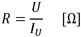
- Der Widerstand R von nicht vulkanisierten Siloxanen wird mit dem Multimeter Model 2110 5 ½ digit von Keithley Instrument und einer angefertigten Messapparatur aus PP Natur und Edelstahl-(1.4571)-Elektroden gemessen. Die Verbindung des Messgeräts mit den Elektroden erfolgt mittels Messingkontakten und Laborleitungen. Die Messapparatur ist eine Form mit definierten Maßen für L x B x H von 16 cm x 3 cm x 0,975 cm, in die das Siloxan zur Messung gestrichen wird. Die beiden äußeren flächigen Elektroden sind im Abstand von 16 cm angebracht, wodurch der Strom die ganze Probe durchströmt. Die beiden Punkt-Elektroden mit einem Durchmesser von 1 cm befinden sich in der Bodenplatte im Abstand von 12 cm (l) und messen die Spannung. Mit folgender Formel wird der spezifische Widerstand aus dem gemessenen Widerstand R berechnet.

- mit Probenhöhe h [cm], Probenbreite w [cm] und Elektrodenabstand l [cm]
- (hier: h = 0,975 cm, w = 3 cm, l = 12 cm)
- Gemäß ISO 37 wurden die Drucktinten in Form einer 2 mm Platte vulkanisiert und der Schulterstab Typ 1 gestanzt. Der Prüfkörper wird einer Vierleitermessung unterzogen. Dieser wird mittig zwischen zwei elektrisch leitfähige Klemmbacken gespannt, so dass deren Abstand voneinander 84,0 mm beträgt. Die Klemmbacken, die die beiden äußeren elektrischen Kontakte darstellen, sind strukturiert, womit durch die Struktur ein Eindringeffekt ins Material (Einstechen) erreicht wird.
- Die beiden inneren Kontakte werden dadurch hergestellt, dass zwei Schnellklemmen in 29,5 mm Entfernung von der jeweils nächsten Klemmbacke und in einem Abstand von 25 cm voneinander positioniert werden. Die beiden inneren Messklemmen werden mit Silberleitpaste vorbehandelt. Der so gemessene Widerstand ohne Dehnung (L=L0) ist R0. Die beiden äußeren Klemmbacken ermöglichen zusätzlich die uniaxiale Dehnung des Prüfkörpers und somit die Messung des Widerstands R der gedruckten Elektrode bei der Dehnung (L-L0)/L0 = 50%.
- Die Mischungen wurden in einem Labotop 1LA der Firma PC Laborsystem GmbH mit einem Fassungsvermögen von 1 Liter bei 300 mbar Vakuum und Raumtemperatur hergestellt. Als Werkzeuge wurden eine Dissolverscheibe (14 Zähne, Zähne 90° zur Scheibe, Durchmesser 52 cm), ein Balkenrührer (Standardwerkzeug) und ein Abstreifer mit Temperaturmessung verwendet. Für größere Ansätze wurde ein Labormischer (Mischtechnik Hoffmann & Partner GmbH Andrä - Wördern, Österreich) mit einem Fassungsvermögen von 10 L mit Zahn-Dissolverscheibe (vier Zähne, Durchmesser 98 mm), Balkenrührer und Abstreifer eingesetzt. Der doppelwandige Rührkessel wurde mit einem Thermostaten auf 19 °C Manteltemperatur eingestellt.
- Zum Mischen der A und B Komponenten wurde ein Laborrührer (IKA RW20) mit 3-flügeligem Propellerrührer (R 1381) von der Firma IKA® -Werke GmbH & Co. KG, Staufen, Deutschland eingesetzt.
- Es wurde ein Dreiwalzenstuhl der Firma EXAKT (Modell 50 l) eingesetzt. Der Walzenspalt wurde auf den minimalen Abstand eingestellt.
- Zur Druckfiltration wurde die Masse in einen zylindrischen Stahlbehälter (Fassungsvermögen 5 L) überführt, der nach oben hin offen und im Boden einen kreisrunden Auslass (Durchmesser 31,5 mm) besitzt. Daran ist ein doppelkonischer Auslass angebracht, in dessen Mitte sich ein kreisrundes Metalldrahtgewebe (Durchmesser 80 mm) befindet. Durch Absenken einer Pressplatte und einem Auspressdruck von 50 bar wurde die Masse vertikal aus dem Stahlbehälter und durch das Metalldrahtgewebe gepresst. Zum Absenken der Pressplatte wurde eine Austrageeinheit mit Hydraulik-Antrieb von der Firma PC Laborsystem eingesetzt.
- Es wurden Metalldrahtgewebe der Firma PACO Paul GmbH & Co. KG oder GKD-Gebr. Kufferath AG aus Chrom-Nickelstahl (X5CrNi18-10, Werkstoff-Nr. nach DIN/DIN EN 1.4301) mit einer Maschenweite von 50 bzw. 25 µm eingesetzt.
- In einem Labormischer mit einem Fassungsvermögen von 10 L mit Zahn-Dissolverscheibe (Durchmesser 98 mm mit vier Zähnen), Balkenrührer und Abstreifer wurden MWCNT (36 g) und 1783 g der Rußvormischung in ViPo 1.000 (581 g) für 60 min bei 1800 rpm (Dissolver) und 50 rpm (Balkenrührer) eingemischt. Der doppelwandige Rührkessel wurde mit einem Thermostaten auf 19 °C Manteltemperatur eingestellt. Es wurde eine homogene, schwarze Paste mit einem spezifischen Widerstand von 5,4 Ω*cm erhalten. Die Viskosität beträgt bei Scherrate 10 s-1 296 Pa*s und das Speichermodul G` im LVE-Bereich 51200 Pa.
- Es wurden MWCNT (1.0 g) und 50,9 g der Rußvormischung in ViPo 1.000 (16,6 g) mit einem Balkenrühren (80 rpm, Labotop ohne Dissolverscheibe) eingerührt (1 min) und anschließend zweimal mit dem Dreiwalzenstuhl eingearbeitet. Es wurde eine homogene, schwarze Paste mit einem spezifischen Widerstand von 6,1 Q*cm erhalten. Die Viskosität beträgt bei Scherrate 10 s-1 280 Pa*s und das Speichermodul G' im LVE-Bereich 48800 Pa.
- 5.0 g MWCNT wurden in 245 g ViPo 1000 mit einem Balkenrühren (80 rpm, Labotop ohne Dissolverscheibe) eingerührt (1 min) und anschließend zweimal mit dem Dreiwalzenstuhl eingearbeitet. Es wurde eine homogene schwarze Paste mit einem spezifischen Widerstand von 6,9 Ω*cm erhalten. Die Viskosität beträgt bei Scherrate 10 s-1 80 Pa*s und das Speichermodul G' im LVE-Bereich 17000 Pa.
- In einem Labormischer Labotop 1LA der Firma PC Laborsystem GmbH mit Zahn-Dissolverscheibe (Durchmesser 52 mm) wurden 0,8 Gew.-% MWCNT (4,0 g) und 200 g der Rußvormischung in eine Mischung aus ViPo 1.000 (108 g), HPo 1.000 (154 g), Vernetzer (20,0 g), Pt-Katalysator (0,4 g) und 1-Ethinyl-1-cyclohexanol (30°mg) für 60 Minuten bei Raumtemperatur, 2.000 rpm (Dissolver) und 200 rpm (Balkenrührer) eingemischt. Die erhaltene Paste wurde unter Druck durch ein Metallgewebe mit einer Maschenweite von 50 µm gepresst. Es wurde eine homogene, schwarze Paste erhalten.
- Drucktinte 1b wurde analog zu Drucktinte 1a hergestellt, mit dem Unterschied, dass die Paste durch ein Metallgewebe mit einer Maschenweite von 25 µm gepresst wurde.
- Drucktinte 1c wurde analog zu Drucktinte 1a hergestellt, mit dem Unterschied, dass die Paste nicht durch ein Metallgewebe gepresst wurde.
- Der Masterbatch M1 aus Beispiel 1 wurde zu einer platinhaltigen Komponente A und einer platinfreien Komponente B verdünnt:
Zur Herstellung der A-Komponente wurden 1000 g des Masterbatch M1 mit Vipo 1000 (855 g) und WACKER® KATALYSATOR OL (3,7 g) für 30 min mit einem Balkenrühren (100 rpm, Labormischer ohne Dissolverscheibe) 30 min gemischt. Daraufhin wurde die Probe unter Druck durch ein Metallgewebe (Maschenweite 50 pm) gepresst. Komponente B wurde analog zu Komponente A hergestellt mit dem Unterschied, dass 1000 g des Masterbatch M1 mit HPo 1000 (465 g), Vernetzer (260 g), Vipo 1000 (134 g) und 1-Ethinyl-1-cyclohexanol (2,6 g) gemischt wurde. Daraufhin wurde die Probe durch ein Metallgewebe (Maschenweite 50 pm) gepresst. - Zur Herstellung der Drucktinte 2b wurden die Komponenten A und B im Verhältnis 1:1 für 1 min mit einem Propellerrührer (800 rpm) gemischt. Es wurde eine homogene, schwarze Paste erhalten.
- Drucktinte 2b wurde analog zu Drucktinte 2a hergestellt, mit dem Unterschied, dass die beiden Komponenten A und B vor dem Mischen nicht durch ein Metallgewebe gepresst wurden. Es wurde eine homogene, schwarze Paste erhalten.
- Der Masterbatch M2 aus Beispiel 2 wurde zu einer platinhaltigen Komponente A und einer platinfreien Komponente B verdünnt:
Zur Herstellung der A-Komponente wurden 30 g des Masterbatch M2 mit Vipo 1000 (25,7 g) und WACKER® KATALYSATOR OL (0,11 g) für 30 min mit einem Balkenrühren (80 rpm, Labotop ohne Dissolverscheibe) für 30 min gemischt. Daraufhin wurde die Probe unter Druck durch ein Metallgewebe (Maschenweite 50 pm) gepresst. Komponente B wurde analog zu Komponente B hergestellt mit dem Unterschied, dass 30 g des Masterbatch M2 mit HPo 1000 (14,0 g), Vernetzer (7,8 g), Vipo 1000 (4,02 g) und 1-Ethinyl-1-cyclohexanol (78 µg) gemischt wurde. Daraufhin wurde die Probe durch ein Metallgewebe (Maschenweite 50 pm) gepresst. - Zur Herstellung der Drucktinte 3a wurden die Komponenten A und B im Verhältnis 1:1 für 1 min mit einem Propellerrührer (800 rpm) gemischt. Es wurde eine homogene, schwarze Paste erhalten.
- Drucktinte 3b wurde analog zu Drucktinte 3a hergestellt, mit dem Unterschied, dass die beiden Komponenten vor dem Mischen nicht durch ein Metallgewebe gepresst wurden. Es wurde eine homogene, schwarze Paste erhalten.
- Zur Herstellung der zweikomponentigen Drucktinte wurde zunächst eine platinhaltige Komponente A und eine platinfreie Komponente B hergestellt.
- Zur Herstellung der Komponente A wurden in einem Labormischer mit einem Fassungsvermögen von 10 L mit Zahn-Dissolverscheibe (Durchmesser 98 mm mit vier Zähnen), Balkenrührer und Abstreifer MWCNT (15 g) und 743 g der Rußvormischung in eine Mischung aus ViPo 1.000 (1097 g) und WACKER® KATALYSATOR OL (3,7 g) für 60 min bei 1800 rpm (Dissolver) und 50 rpm (Balkenrührer) eingemischt. Der doppelwandige Rührkessel wurde mit einem Thermostaten auf 19 °C Manteltemperatur eingestellt. Daraufhin wurde die Probe A unter Druck durch ein Metallgewebe (Maschenweite 50 pm) gepresst. Komponente B wurde aus MWCNT (15 g), 743 g der Rußvormischung, HPo 1000 (465 g), Vernetzer (260 g), Vipo 1000 (373 g) und 1-Ethinyl-1-cyclohexanol (2,61 g) analog zu A hergestellt. Daraufhin wurde die Probe B unter Druck durch ein Metallgewebe (Maschenweite 50 pm) gepresst. Zur Herstellung der Drucktinte 4a wurden die Komponenten A und B im Verhältnis 1:1 für 1 min mit einem Propellerrührer (800 rpm) gemischt. Es wurde eine homogene, schwarze Paste erhalten.
- Drucktinte 4b wurde analog zu Drucktinte 4a hergestellt, mit dem Unterschied, dass die beiden Komponenten vor dem Mischen nicht durch ein Metallgewebe gepresst wurden.
- Die Herstellung erfolgte analog Drucktinte 1a, mit dem Unterschied, dass 192 g Masterbatch M3 (entspricht 0,8 Gew% MWCNT), 192 g der Rußvormischung in einer Mischung aus ViPo 1.000 (21,2 g), HPo 1.000 (41,4 g) und Vernetzer (33,6 g) eingesetzt wurden. Die erhaltene Paste wurde unter Druck durch ein Metallgewebe (Maschenweite 50 pm) gepresst. Es wurde eine homogene, schwarze Paste erhalten.
- Drucktinte 5b wurde analog zu Drucktinte 5a hergestellt, mit dem Unterschied, dass die Paste nicht durch ein Metallgewebe gepresst wurde.
- Die Herstellung erfolgte analog Drucktinte 1a, mit dem Unterschied, dass 0,4 Gew.-% MWCNT (2,0 g), 280 g der Rußvormischung (entspricht 2,8 Gew% Ruß in der finalen Rezeptur) in einer Mischung aus ViPo 1.000 (48.1 g) und HPo 1.000 (150 g) eingesetzt wurden. Die erhaltene Paste wurde unter Druck durch ein Metallgewebe (Maschenweite 50 pm) gepresst. Es wurde eine homogene, schwarze Paste erhalten.
- Drucktinte 6b wurde analog zu Drucktinte 6a hergestellt, mit dem Unterschied, dass die Paste nicht durch ein Metallgewebe gepresst wurde.
- Die Herstellung erfolgte analog Drucktinte 1a, mit dem Unterschied, dass 1,0 Gew.-% MWCNT (5,0 g), 100 g der Rußvormischung (entspricht 1,0 Gew% Ruß in der finalen Rezeptur) in einer Mischung aus ViPo 1.000 (221 g) und HPo 1.000 (153 g) eingesetzt wurden. Die erhaltene Paste wurde unter Druck durch ein Metallgewebe (Maschenweite 50 pm) gepresst. Es wurde eine homogene, schwarze Paste erhalten.
- Drucktinte 7b wurde analog zu Drucktinte 7a hergestellt, mit dem Unterschied, dass die Paste nicht durch ein Metallgewebe gepresst wurde.
- Die Herstellung erfolgte analog Drucktinte 1a, mit dem Unterschied, dass 1,2 Gew.-% MWCNT (6,0 g), 200 g der Rußvormischung (entspricht 2,0 Gew% Ruß in der finalen Rezeptur) in einer Mischung aus ViPo 1.000 (124 g) und HPo 1.000 (150 g) eingesetzt wurden. Die erhaltene Paste wird unter Druck durch ein Metallgewebe (Maschenweite 50 µm) gepresst. Es wurde eine homogene, schwarze Paste erhalten.
- Drucktinte 8b wurde analog zu Drucktinte 8a hergestellt, mit dem Unterschied, dass die Paste nicht durch ein Metallgewebe gepresst wurde.
- Die Herstellung erfolgte analog Drucktinte 1a, mit dem Unterschied, dass 1,5 Gew.-% MWCNT (7,5 g), 100 g der Rußvormischung (entspricht 1,0 Gew% Ruß in der finalen Rezeptur) in einer Mischung aus ViPo 1.000 (221 g) und HPo 1.000 (152 g) eingesetzt wurden. Die erhaltene Paste wurde unter Druck durch ein Metallgewebe (Maschenweite 50 µm) gepresst. Es wurde eine homogene, schwarze Paste erhalten.
- Drucktinte 9b wurde analog zu Drucktinte 9a hergestellt, mit dem Unterschied, dass die Paste nicht durch ein Metallgewebe gepresst wurde.
- Die Herstellung erfolgte analog Drucktinte 1a, mit dem Unterschied, dass 1,2 Gew.-% MWCNT (2,4 g), 100 g der Rußvormischung (entspricht 2,5 Gew% Ruß in der finalen Rezeptur) in einer Mischung aus ViPo 1.000 (28,3 g) und HPo 1.000 (59,3 g), Vernetzer (8 g) Pt-Katalysator (160 mg) und 1-Ethinyl-1-cyclohexanol (12°mg) eingesetzt wurden. Die erhaltene Paste wurde unter Druck durch ein Metallgewebe (Maschenweite 50 µm) gepresst. Es wurde eine homogene, schwarze Paste erhalten.
- Die Drucktinte 10b wurde analog zu Drucktinte 10a hergestellt, mit dem Unterschied, dass die Paste nicht durch ein Metallgewebe gepresst wurde.
- Die Herstellung erfolgte analog Drucktinte 1a, mit dem Unterschied, dass 2,0 Gew.-% MWCNT (10 g), 300 g der Rußvormischung (entspricht 3,0 Gew% Ruß in der finalen Rezeptur) in einer Mischung aus ViPo 1.000 (25,3 g) und HPo 1.000 (144 g) eingesetzt wurden. Die erhaltene Paste wird unter Druck durch ein Metallgewebe (Maschenweite 50 pm) gepresst. Es wurde eine homogene, schwarze Paste erhalten. Es wurde eine homogene, schwarze Paste erhalten.
- Die Drucktinte 11b wurde analog zu Drucktinte 11a hergestellt, mit dem Unterschied, dass die Paste nicht durch ein Metallgewebe gepresst wurde.
- Der LIFT Prozess wurde wie in
WO2020156632 beschrieben durchgeführt. Das Drucken erfolgte mit einem gängigen Laser-Gravursystem der Firma TROTEC Laser Deutschland GmbH. Zur Anwendung kommt dabei ein System der Baureihe Speedy 100flexx 60/20 mit Dual Laserquelle (60 W 10,6 µm CO2 Laser; 20 W 1064 nm Faser-Laser). Als Träger und Druckmassenträger werden gängige Quarzglasplatten (300x300x3 mm) der Firma GVB GmbH Solutions in Glass, Deutschland, verwendet. Zur Aufbringung des Druckmassenfilmes wird ein ZAA 2300 Automatisches Filmziehgerät mit einem ZUA 2000 Universal-Applikator der Firma Zehntner GmbH, Schweiz, verwendet. - Mit dem Rakelsystem wird einseitig auf einer Quarzglasscheibe eine homogene Schicht in einer Dicke von 60 µm und in den Abmessungen 200x 200mm mittig aufgerakelt. Die Randbereiche der Scheibe bleiben dabei frei von Druckmasse. In den Schneidraum des Lasers wird auf eine unbeschichtete Glasscheibe durch einen Wasserfilm fixierte Siliconfolie (ELASTOSIL<®>-Film mit 100 µm Dicke, erhältlich bei der WACKER Chemie AG) als zu bedruckende Fläche eingelegt. Die beschichtete Scheibe wird mit der Beschichtungsseite der unbeschichteten Scheibe zugewandt, in einem Abstand von 200 µm auf der ersten Scheibe platziert. Der Abstand wird dabei durch Abstandshalter wie beispielsweise 100 µm Mikroskopplatten eingestellt. Als Druckvorlage in der Steuersoftware des Lasersystems, ist eine flächig gefüllte Geometrie ohne Graubereiche und Schattierungen zu wählen. Weiter ist die Laserleistung im Schneidmodus Faserlaser zwischen 40-60 % bei einem 20 W Laser ausreichend. Der Laserspeed ist zwischen 50 und 70 % zu wählen. Der Fokuspunkt sollte ca. 4 bis 4,5 mm oberhalb der Grenzfläche Beschichtung bzw. der Quarzglasplatte liegen. Die gewählten Geometrien konnten so durch den Laser auf die Siliconfolie transferiert werden.
- Die Oberfläche der gedruckten Elektrode wurde optisch beurteilt. Die Schichten, die mit den Drucktinten 1a, 1b, 2a, 3a, 4a, 5a, 6a, 7a, 8a, 9a, 10a und 11a gedruckt wurden, waren glatt, glänzend und frei von herausstehenden Zacken. Diese Drucktinten sind somit als Elektrodenmaterial für mehrlagige Systeme wie z.B. in dielektrischen Elastomersensoren, -aktoren und -generatoren besonders gut geeignet.
- Mit den Drucktinten 1c, 2b, 3b, 4b, 5b, 6b, 7b, 8b, 9b, 10b und 11b gedruckte Schichten weisen Oberflächen mit aus der Schicht heraustretenden Zacken auf und sind somit für mehrlagige Systeme ungeeignet.
- Die folgende Tabelle stellt die in den Beispielen verwendeten Mengen an MWCNT, Ruß, die zur Filtration eingesetzten Maschenweiten sowie die Ergebnisse der Messungen gegenüber.
Drucktinte Nr. MWCNT (Gew-%) Ruß (Gew-% ) Maschen weite [pm] Viskosi tät [Pas] G' [kPa] spez. Widerstand [Ω*cm] R/R0 1a 0, 8 2, 0 50 79 11 8, 8 1, 6 1b 25 79 11 8, 8 1, 6 1c - 79 11 8, 8 1, 6 2a 0, 8 2, 0 50 66 8, 7 11 1, 6 2b - 69 8,5 11 1, 6 3a 0, 8 2, 0 50 77 9, 3 9, 5 1, 6 3b - 75 9, 0 9, 5 1, 6 4a 0, 8 2, 0 50 80 10 9, 5 1, 6 4b - 80 10 9, 5 1, 6 5a 0, 8 2, 0 50 81 9, 5 9, 0 1, 6 5b - 81 9, 5 9, 0 1, 6 6a 0,4 2,8 50 67 6, 7 18 1, 8 6b - 67 6, 6 18 1, 8 7a 1, 0 1, 0 50 51 6, 3 19 1, 2 7b - 51 6, 3 19 1, 2 8a 1,2 2, 0 50 100 19 6, 8 1, 2 8b - 100 18 6, 8 1, 2 9a 1,5 1, 0 50 80 15 5, 1 1, 2 9b - 79 15 5, 1 1, 2 10a 1,2 2,5 50 151 23 7, 8 1, 2 10b - 151 24 7, 8 1, 2 11a 2,0 3, 0 50 300 88 3, 9 1, 1 11b - 300 88 3, 9 1, 1
Claims (6)
- Verfahren zur Herstellung einer elektrisch leitfähigen, vernetzenden Silikonelastomerzusammensetzung,enthaltend:- 0,5 bis 3,0 Gew.% Leitfähigkeitsruß,- 0,1 bis 3,0 Gew.% mehrwandige Kohlenstoffnanoröhren (MWCNT),- kein Lösungsmittel,mit der Maßgabe, dassa) wenn die Silikonelastomerzusammensetzung einkomponentig formuliert wird, alle Komponenten in einem oder in mehreren Schritten vermischt werden und anschließend eine Druckfiltration durch ein Metallgewebe mit einer Maschenweite von höchstens 200 µm erfolgt, oder dassb) wenn die Silikonelastomerzusammensetzung zweikomponentig formuliert wird, jeweils nur die Komponenten der A- bzw. der B-Zusammensetzung in einem oder in mehreren Schritten vermischt werden und anschließend jeweils eine Druckfiltration der A- bzw. der B-Zusammensetzung durch ein Metallgewebe mit einer Maschenweite von höchstens 200 µm erfolgt.
- Verfahren gemäß Anspruch 1, dadurch gekennzeichnet, dass es eine elektrisch leitfähige, additionsvernetzende Silikonelastomerzusammensetzung ist, und folgende Kompononenten enthält:(A) mindestens eine lineare Verbindung, die Reste mit aliphatischen Kohlenstoff-Kohlenstoff-Mehrfachbindungen aufweist,(B) mindestens eine -bevorzugt lineare - Organopolysiloxan Verbindung mit Si-gebundenen Wasserstoffatomen,
oder anstelle von (A) und (B) oder zusätzlich zu (A) und (B)(C) mindestens eine lineare Organopolysiloxan Verbindung, die Si-C-gebundene Reste mit aliphatischen Kohlenstoff-Kohlenstoff Mehrfachbindungen und Si-gebundene Wasserstoffatome aufweist, und(D) mindestens einen Hydrosilylierungskatalysator. - Elektisch leitfähige vernetzende Silikonelastomerzusammensetzung erhältlich nach einem der Verfahren gemäß den Ansprüchen 1 bis 2.
- Verwendung der leitfähigen vernetzenden Silikonelastomerzusammensetzung gemäß Anspruch 3 als elektrisch leitfähige Drucktinte in kontaktlosen Druckverfahren zur Herstellung von elektrisch leitfähigen Elastomeren auf elastischen Trägern.
- Verwendung gemäß Anspruch 4, dadurch gekennzeichnet, dass das kontaktlose Druckverfahren der Laser-Transferdruck ist.
- Verwendung gemäß Anspruch 4 und 5, dadurch gekennzeichnet, dass die hergestellten elektrisch leitfähigen Elastomere auf elastischen Trägern Elektroden für dielektrische Elastomersensoren, -aktoren und -generatoren und EAP-Schichtsysteme sind.
Applications Claiming Priority (1)
| Application Number | Priority Date | Filing Date | Title |
|---|---|---|---|
| PCT/EP2021/078319 WO2023061578A1 (de) | 2021-10-13 | 2021-10-13 | Elektrisch leitfähige elastomere drucktinte für kontaktlose druckverfahren |
Publications (2)
| Publication Number | Publication Date |
|---|---|
| EP4364536A1 EP4364536A1 (de) | 2024-05-08 |
| EP4364536B1 true EP4364536B1 (de) | 2025-01-29 |
Family
ID=78134988
Family Applications (1)
| Application Number | Title | Priority Date | Filing Date |
|---|---|---|---|
| EP21790901.9A Active EP4364536B1 (de) | 2021-10-13 | 2021-10-13 | Elektrisch leitfähige elastomere drucktinte für kontaktlose druckverfahren |
Country Status (6)
| Country | Link |
|---|---|
| US (1) | US20240368420A1 (de) |
| EP (1) | EP4364536B1 (de) |
| JP (1) | JP7690618B2 (de) |
| KR (1) | KR20240058144A (de) |
| CN (1) | CN117413623A (de) |
| WO (1) | WO2023061578A1 (de) |
Families Citing this family (1)
| Publication number | Priority date | Publication date | Assignee | Title |
|---|---|---|---|---|
| CN118103925A (zh) * | 2021-10-13 | 2024-05-28 | 瓦克化学股份公司 | 具有碳纳米管和炭黑的导电硅酮组合物 |
Family Cites Families (14)
| Publication number | Priority date | Publication date | Assignee | Title |
|---|---|---|---|---|
| JP5380022B2 (ja) * | 2007-09-19 | 2014-01-08 | 電気化学工業株式会社 | 有機無機複合組成物 |
| DE102007047212A1 (de) | 2007-10-02 | 2009-04-09 | Wacker Chemie Ag | Härtbare Siliconzusammensetzungen |
| KR20110030539A (ko) | 2008-06-18 | 2011-03-23 | 바스프 에스이 | 태양 전지용 전극의 제조 방법 |
| PH12011501221A1 (en) | 2008-12-17 | 2010-06-24 | Basf Se | Method and printing press for printing a substrate |
| KR20130036293A (ko) * | 2010-06-22 | 2013-04-11 | 바스프 에스이 | 전극 및 이의 제조방법 및 용도 |
| US20140014403A1 (en) * | 2011-07-11 | 2014-01-16 | Robert J. Miller | Energy storage and dispensing flexible sheeting device |
| JP5807112B2 (ja) | 2012-03-29 | 2015-11-10 | 住友理工株式会社 | 導電膜 |
| JP5872964B2 (ja) * | 2012-05-29 | 2016-03-01 | 東レ・ダウコーニング株式会社 | 導電性室温硬化型フルオロシリコーンゴム組成物 |
| JP6065780B2 (ja) | 2012-08-30 | 2017-01-25 | 信越化学工業株式会社 | 導電性回路描画用インク組成物、導電性回路形成方法及びそれにより形成された導電性回路 |
| CN103160128B (zh) | 2013-04-10 | 2015-03-11 | 北京化工大学 | 一种极低压缩变形低硬度的导电硅橡胶材料及制备方法 |
| CA2939114A1 (en) * | 2014-02-21 | 2015-08-27 | Kratos LLC | Nanosilicon material preparation for functionalized group iva particle frameworks |
| CN106414791A (zh) | 2014-05-27 | 2017-02-15 | 奥博泰克有限公司 | 藉由激光诱发正向转印以印刷三维结构 |
| US9530533B2 (en) | 2015-05-28 | 2016-12-27 | Honda Motor Co., Ltd. | Conductive paste composition |
| JP7019834B2 (ja) | 2019-01-28 | 2022-02-15 | ワッカー ケミー アクチエンゲゼルシャフト | レーザー転写印刷による少なくとも1つのシリコーン層の塗布方法 |
-
2021
- 2021-10-13 WO PCT/EP2021/078319 patent/WO2023061578A1/de not_active Ceased
- 2021-10-13 EP EP21790901.9A patent/EP4364536B1/de active Active
- 2021-10-13 JP JP2023579515A patent/JP7690618B2/ja active Active
- 2021-10-13 US US18/686,454 patent/US20240368420A1/en active Pending
- 2021-10-13 CN CN202180098853.1A patent/CN117413623A/zh active Pending
- 2021-10-13 KR KR1020247011042A patent/KR20240058144A/ko active Pending
Also Published As
| Publication number | Publication date |
|---|---|
| EP4364536A1 (de) | 2024-05-08 |
| US20240368420A1 (en) | 2024-11-07 |
| JP7690618B2 (ja) | 2025-06-10 |
| KR20240058144A (ko) | 2024-05-03 |
| WO2023061578A1 (de) | 2023-04-20 |
| JP2024531042A (ja) | 2024-08-29 |
| CN117413623A (zh) | 2024-01-16 |
Similar Documents
| Publication | Publication Date | Title |
|---|---|---|
| DE69627622T2 (de) | Flexible Dickschichtleiterzusammensetzung | |
| DE2752540C2 (de) | Druckempfindliches elektrisches Widerstandselement und Verfahren zu dessen Herstellung | |
| DE69218128T2 (de) | Härtbare Organosiloxanzusammensetzungen, die elektrisch leitfähige Materialien ergeben | |
| EP2775483B1 (de) | Elektrisch leitendes Material und dessen Verwendung als Elektrode in einem dielektrischen Elastomerkomposit oder als elektrisch leitende, dehnbare Faser | |
| EP2468826A1 (de) | Pickering-Emulsion zur Herstellung elektrisch leitfähiger Beschichtungen und Verfahren zur Herstellung einer Pickering-Emulsion | |
| EP2369598A1 (de) | Herstellung leitfähiger Oberflächenbeschichtungen mit Dispersion mit elektrostatisch stabilisierten Silbernanopartikeln | |
| EP4364536B1 (de) | Elektrisch leitfähige elastomere drucktinte für kontaktlose druckverfahren | |
| DE2643468A1 (de) | Siloxanmassen | |
| DE2543455B2 (de) | Verfahren zum Herstellen eines elastisch verformbaren Materials mit druckabhangigem elektrischen Widerstand | |
| WO2017054792A1 (de) | Verfahren zur herstellung einer anordnung aus elektrisch leitfähiger schicht auf einem substrat aus einer suspension, sowie anordnung aus elektrisch leitfähiger schicht auf einem substrat und deren verwendung | |
| DE112020007642T5 (de) | Metallpaste zum verbinden und verbindungsverfahren | |
| WO2023237192A1 (de) | Elektrisch leitfähige elastomere drucktinte für kontaktlose druckverfahren | |
| WO2015104015A2 (de) | Sensorelement zur bestimmung von dehnungen | |
| EP3685409B1 (de) | Zusammensetzung zum herstellen einer elektrisch leitfähigen schicht, insbesondere für eine elektrolumineszenz-vorrichtung | |
| WO2006128403A1 (de) | Elektrisch leitfähiges material und ein verfahren zur herstellung eines elektrisch leitfähigen materials | |
| EP3865545B1 (de) | Korrosionsschutz-zusammensetzung | |
| EP4114893B1 (de) | Elektrisch leitfähige paste | |
| WO2023061579A1 (de) | ELEKTRISCH LEITFÄHIGE SILICONZUSAMMENSETZUNG MIT KOHLENSTOFFNANORÖHREN UND RUß | |
| EP3341135B1 (de) | Verfahren zur generativen herstellung von dielektrischen elastomer-aktoren sowie einen druckkopf zur durchführung des verfahrens | |
| DE112019003063B4 (de) | Dielektrische Polymerdickschichtpastenzusammensetzung | |
| DE102020120642A1 (de) | Funktionseinheit, elektronisches Bauteil und Verfahren zur Herstellung einer Funktionseinheit | |
| EP4025427B1 (de) | Formulierung von cnt-haltigen siloxanen enthaltend kieselsäure | |
| DE102011122630B4 (de) | Verfahren zur Herstellung eines Beschichtungsmaterials für Strahlungsflächen zur Erzeugung und/oder Abstrahlung von elektromagnetischen Wellen, insbesondere einer Wärmestrahlung, sowie Beschichtungsmaterial für Strahlungsflächen | |
| DE102023211658A1 (de) | Wässrige, leitfähige, druckbare Ruß-gefüllte Tinte, Verfahren zu deren Herstellung, beschichteter Gegenstand sowie Verfahren zur Herstellung des be-schichteten Gegenstands | |
| DE2812401C3 (de) | Zu Elastomeren vulkanisierbare Polysiloxanformmasse |
Legal Events
| Date | Code | Title | Description |
|---|---|---|---|
| STAA | Information on the status of an ep patent application or granted ep patent |
Free format text: STATUS: UNKNOWN |
|
| STAA | Information on the status of an ep patent application or granted ep patent |
Free format text: STATUS: THE INTERNATIONAL PUBLICATION HAS BEEN MADE |
|
| PUAI | Public reference made under article 153(3) epc to a published international application that has entered the european phase |
Free format text: ORIGINAL CODE: 0009012 |
|
| STAA | Information on the status of an ep patent application or granted ep patent |
Free format text: STATUS: REQUEST FOR EXAMINATION WAS MADE |
|
| 17P | Request for examination filed |
Effective date: 20240129 |
|
| AK | Designated contracting states |
Kind code of ref document: A1 Designated state(s): AL AT BE BG CH CY CZ DE DK EE ES FI FR GB GR HR HU IE IS IT LI LT LU LV MC MK MT NL NO PL PT RO RS SE SI SK SM TR |
|
| P01 | Opt-out of the competence of the unified patent court (upc) registered |
Effective date: 20240513 |
|
| RAP3 | Party data changed (applicant data changed or rights of an application transferred) |
Owner name: WACKER CHEMIE AG |
|
| GRAP | Despatch of communication of intention to grant a patent |
Free format text: ORIGINAL CODE: EPIDOSNIGR1 |
|
| STAA | Information on the status of an ep patent application or granted ep patent |
Free format text: STATUS: GRANT OF PATENT IS INTENDED |
|
| DAV | Request for validation of the european patent (deleted) | ||
| DAX | Request for extension of the european patent (deleted) | ||
| INTG | Intention to grant announced |
Effective date: 20240919 |
|
| GRAS | Grant fee paid |
Free format text: ORIGINAL CODE: EPIDOSNIGR3 |
|
| GRAA | (expected) grant |
Free format text: ORIGINAL CODE: 0009210 |
|
| STAA | Information on the status of an ep patent application or granted ep patent |
Free format text: STATUS: THE PATENT HAS BEEN GRANTED |
|
| RIN1 | Information on inventor provided before grant (corrected) |
Inventor name: KOELLNBERGER, ANDREAS Inventor name: SURARU, SABIN-LUCIAN |
|
| AK | Designated contracting states |
Kind code of ref document: B1 Designated state(s): AL AT BE BG CH CY CZ DE DK EE ES FI FR GB GR HR HU IE IS IT LI LT LU LV MC MK MT NL NO PL PT RO RS SE SI SK SM TR |
|
| REG | Reference to a national code |
Ref country code: GB Ref legal event code: FG4D Free format text: NOT ENGLISH |
|
| REG | Reference to a national code |
Ref country code: CH Ref legal event code: EP |
|
| REG | Reference to a national code |
Ref country code: DE Ref legal event code: R096 Ref document number: 502021006546 Country of ref document: DE |
|
| REG | Reference to a national code |
Ref country code: IE Ref legal event code: FG4D Free format text: LANGUAGE OF EP DOCUMENT: GERMAN |
|
| REG | Reference to a national code |
Ref country code: NL Ref legal event code: MP Effective date: 20250129 |
|
| PG25 | Lapsed in a contracting state [announced via postgrant information from national office to epo] |
Ref country code: NL Free format text: LAPSE BECAUSE OF FAILURE TO SUBMIT A TRANSLATION OF THE DESCRIPTION OR TO PAY THE FEE WITHIN THE PRESCRIBED TIME-LIMIT Effective date: 20250129 |
|
| PG25 | Lapsed in a contracting state [announced via postgrant information from national office to epo] |
Ref country code: RS Free format text: LAPSE BECAUSE OF FAILURE TO SUBMIT A TRANSLATION OF THE DESCRIPTION OR TO PAY THE FEE WITHIN THE PRESCRIBED TIME-LIMIT Effective date: 20250429 |
|
| PG25 | Lapsed in a contracting state [announced via postgrant information from national office to epo] |
Ref country code: FI Free format text: LAPSE BECAUSE OF FAILURE TO SUBMIT A TRANSLATION OF THE DESCRIPTION OR TO PAY THE FEE WITHIN THE PRESCRIBED TIME-LIMIT Effective date: 20250129 |
|
| PG25 | Lapsed in a contracting state [announced via postgrant information from national office to epo] |
Ref country code: PL Free format text: LAPSE BECAUSE OF FAILURE TO SUBMIT A TRANSLATION OF THE DESCRIPTION OR TO PAY THE FEE WITHIN THE PRESCRIBED TIME-LIMIT Effective date: 20250129 |
|
| PG25 | Lapsed in a contracting state [announced via postgrant information from national office to epo] |
Ref country code: ES Free format text: LAPSE BECAUSE OF FAILURE TO SUBMIT A TRANSLATION OF THE DESCRIPTION OR TO PAY THE FEE WITHIN THE PRESCRIBED TIME-LIMIT Effective date: 20250129 |
|
| REG | Reference to a national code |
Ref country code: LT Ref legal event code: MG9D |
|
| PG25 | Lapsed in a contracting state [announced via postgrant information from national office to epo] |
Ref country code: NO Free format text: LAPSE BECAUSE OF FAILURE TO SUBMIT A TRANSLATION OF THE DESCRIPTION OR TO PAY THE FEE WITHIN THE PRESCRIBED TIME-LIMIT Effective date: 20250429 Ref country code: IS Free format text: LAPSE BECAUSE OF FAILURE TO SUBMIT A TRANSLATION OF THE DESCRIPTION OR TO PAY THE FEE WITHIN THE PRESCRIBED TIME-LIMIT Effective date: 20250529 |
|
| PG25 | Lapsed in a contracting state [announced via postgrant information from national office to epo] |
Ref country code: HR Free format text: LAPSE BECAUSE OF FAILURE TO SUBMIT A TRANSLATION OF THE DESCRIPTION OR TO PAY THE FEE WITHIN THE PRESCRIBED TIME-LIMIT Effective date: 20250129 |
|
| PG25 | Lapsed in a contracting state [announced via postgrant information from national office to epo] |
Ref country code: LV Free format text: LAPSE BECAUSE OF FAILURE TO SUBMIT A TRANSLATION OF THE DESCRIPTION OR TO PAY THE FEE WITHIN THE PRESCRIBED TIME-LIMIT Effective date: 20250129 Ref country code: PT Free format text: LAPSE BECAUSE OF FAILURE TO SUBMIT A TRANSLATION OF THE DESCRIPTION OR TO PAY THE FEE WITHIN THE PRESCRIBED TIME-LIMIT Effective date: 20250529 |
|
| PG25 | Lapsed in a contracting state [announced via postgrant information from national office to epo] |
Ref country code: BG Free format text: LAPSE BECAUSE OF FAILURE TO SUBMIT A TRANSLATION OF THE DESCRIPTION OR TO PAY THE FEE WITHIN THE PRESCRIBED TIME-LIMIT Effective date: 20250129 Ref country code: GR Free format text: LAPSE BECAUSE OF FAILURE TO SUBMIT A TRANSLATION OF THE DESCRIPTION OR TO PAY THE FEE WITHIN THE PRESCRIBED TIME-LIMIT Effective date: 20250430 |
|
| PG25 | Lapsed in a contracting state [announced via postgrant information from national office to epo] |
Ref country code: SE Free format text: LAPSE BECAUSE OF FAILURE TO SUBMIT A TRANSLATION OF THE DESCRIPTION OR TO PAY THE FEE WITHIN THE PRESCRIBED TIME-LIMIT Effective date: 20250129 |
|
| PG25 | Lapsed in a contracting state [announced via postgrant information from national office to epo] |
Ref country code: SM Free format text: LAPSE BECAUSE OF FAILURE TO SUBMIT A TRANSLATION OF THE DESCRIPTION OR TO PAY THE FEE WITHIN THE PRESCRIBED TIME-LIMIT Effective date: 20250129 |
|
| PG25 | Lapsed in a contracting state [announced via postgrant information from national office to epo] |
Ref country code: DK Free format text: LAPSE BECAUSE OF FAILURE TO SUBMIT A TRANSLATION OF THE DESCRIPTION OR TO PAY THE FEE WITHIN THE PRESCRIBED TIME-LIMIT Effective date: 20250129 |
|
| PG25 | Lapsed in a contracting state [announced via postgrant information from national office to epo] |
Ref country code: IT Free format text: LAPSE BECAUSE OF FAILURE TO SUBMIT A TRANSLATION OF THE DESCRIPTION OR TO PAY THE FEE WITHIN THE PRESCRIBED TIME-LIMIT Effective date: 20250129 |
|
| PG25 | Lapsed in a contracting state [announced via postgrant information from national office to epo] |
Ref country code: EE Free format text: LAPSE BECAUSE OF FAILURE TO SUBMIT A TRANSLATION OF THE DESCRIPTION OR TO PAY THE FEE WITHIN THE PRESCRIBED TIME-LIMIT Effective date: 20250129 Ref country code: CZ Free format text: LAPSE BECAUSE OF FAILURE TO SUBMIT A TRANSLATION OF THE DESCRIPTION OR TO PAY THE FEE WITHIN THE PRESCRIBED TIME-LIMIT Effective date: 20250129 |
|
| PG25 | Lapsed in a contracting state [announced via postgrant information from national office to epo] |
Ref country code: RO Free format text: LAPSE BECAUSE OF FAILURE TO SUBMIT A TRANSLATION OF THE DESCRIPTION OR TO PAY THE FEE WITHIN THE PRESCRIBED TIME-LIMIT Effective date: 20250129 |
|
| PG25 | Lapsed in a contracting state [announced via postgrant information from national office to epo] |
Ref country code: SK Free format text: LAPSE BECAUSE OF FAILURE TO SUBMIT A TRANSLATION OF THE DESCRIPTION OR TO PAY THE FEE WITHIN THE PRESCRIBED TIME-LIMIT Effective date: 20250129 |
|
| REG | Reference to a national code |
Ref country code: DE Ref legal event code: R097 Ref document number: 502021006546 Country of ref document: DE |
|
| PLBE | No opposition filed within time limit |
Free format text: ORIGINAL CODE: 0009261 |
|
| STAA | Information on the status of an ep patent application or granted ep patent |
Free format text: STATUS: NO OPPOSITION FILED WITHIN TIME LIMIT |
|
| 26N | No opposition filed |
Effective date: 20251030 |
|
| PGFP | Annual fee paid to national office [announced via postgrant information from national office to epo] |
Ref country code: DE Payment date: 20251021 Year of fee payment: 5 |
|
| PGFP | Annual fee paid to national office [announced via postgrant information from national office to epo] |
Ref country code: GB Payment date: 20251022 Year of fee payment: 5 |
|
| PGFP | Annual fee paid to national office [announced via postgrant information from national office to epo] |
Ref country code: AT Payment date: 20260113 Year of fee payment: 5 |
|
| PGFP | Annual fee paid to national office [announced via postgrant information from national office to epo] |
Ref country code: FR Payment date: 20251030 Year of fee payment: 5 |