EP4365366A1 - Machine à laver - Google Patents
Machine à laver Download PDFInfo
- Publication number
- EP4365366A1 EP4365366A1 EP22883749.8A EP22883749A EP4365366A1 EP 4365366 A1 EP4365366 A1 EP 4365366A1 EP 22883749 A EP22883749 A EP 22883749A EP 4365366 A1 EP4365366 A1 EP 4365366A1
- Authority
- EP
- European Patent Office
- Prior art keywords
- drum
- tub
- washing machine
- flange
- exhaust
- Prior art date
- Legal status (The legal status is an assumption and is not a legal conclusion. Google has not performed a legal analysis and makes no representation as to the accuracy of the status listed.)
- Pending
Links
Images





Classifications
-
- D—TEXTILES; PAPER
- D06—TREATMENT OF TEXTILES OR THE LIKE; LAUNDERING; FLEXIBLE MATERIALS NOT OTHERWISE PROVIDED FOR
- D06F—LAUNDERING, DRYING, IRONING, PRESSING OR FOLDING TEXTILE ARTICLES
- D06F37/00—Details specific to washing machines covered by groups D06F21/00 - D06F25/00
- D06F37/26—Casings; Tubs
- D06F37/267—Tubs specially adapted for mounting thereto components or devices not provided for in preceding subgroups
-
- D—TEXTILES; PAPER
- D06—TREATMENT OF TEXTILES OR THE LIKE; LAUNDERING; FLEXIBLE MATERIALS NOT OTHERWISE PROVIDED FOR
- D06F—LAUNDERING, DRYING, IRONING, PRESSING OR FOLDING TEXTILE ARTICLES
- D06F58/00—Domestic laundry dryers
- D06F58/02—Domestic laundry dryers having dryer drums rotating about a horizontal axis
- D06F58/04—Details
- D06F58/06—Mountings for the rotating drums
-
- D—TEXTILES; PAPER
- D06—TREATMENT OF TEXTILES OR THE LIKE; LAUNDERING; FLEXIBLE MATERIALS NOT OTHERWISE PROVIDED FOR
- D06F—LAUNDERING, DRYING, IRONING, PRESSING OR FOLDING TEXTILE ARTICLES
- D06F25/00—Washing machines with receptacles, e.g. perforated, having a rotary movement, e.g. oscillatory movement, the receptacle serving both for washing and for centrifugally separating water from the laundry and having further drying means, e.g. using hot air
-
- D—TEXTILES; PAPER
- D06—TREATMENT OF TEXTILES OR THE LIKE; LAUNDERING; FLEXIBLE MATERIALS NOT OTHERWISE PROVIDED FOR
- D06F—LAUNDERING, DRYING, IRONING, PRESSING OR FOLDING TEXTILE ARTICLES
- D06F37/00—Details specific to washing machines covered by groups D06F21/00 - D06F25/00
- D06F37/02—Rotary receptacles, e.g. drums
- D06F37/04—Rotary receptacles, e.g. drums adapted for rotation or oscillation about a horizontal or inclined axis
-
- D—TEXTILES; PAPER
- D06—TREATMENT OF TEXTILES OR THE LIKE; LAUNDERING; FLEXIBLE MATERIALS NOT OTHERWISE PROVIDED FOR
- D06F—LAUNDERING, DRYING, IRONING, PRESSING OR FOLDING TEXTILE ARTICLES
- D06F37/00—Details specific to washing machines covered by groups D06F21/00 - D06F25/00
- D06F37/26—Casings; Tubs
-
- D—TEXTILES; PAPER
- D06—TREATMENT OF TEXTILES OR THE LIKE; LAUNDERING; FLEXIBLE MATERIALS NOT OTHERWISE PROVIDED FOR
- D06F—LAUNDERING, DRYING, IRONING, PRESSING OR FOLDING TEXTILE ARTICLES
- D06F37/00—Details specific to washing machines covered by groups D06F21/00 - D06F25/00
- D06F37/26—Casings; Tubs
- D06F37/261—Tubs made by a specially selected manufacturing process or characterised by their assembly from elements
- D06F37/263—Tubs made by a specially selected manufacturing process or characterised by their assembly from elements assembled from at least two elements connected to each other; Connecting or sealing means therefor
-
- D—TEXTILES; PAPER
- D06—TREATMENT OF TEXTILES OR THE LIKE; LAUNDERING; FLEXIBLE MATERIALS NOT OTHERWISE PROVIDED FOR
- D06F—LAUNDERING, DRYING, IRONING, PRESSING OR FOLDING TEXTILE ARTICLES
- D06F37/00—Details specific to washing machines covered by groups D06F21/00 - D06F25/00
- D06F37/30—Driving arrangements
- D06F37/304—Arrangements or adaptations of electric motors
-
- D—TEXTILES; PAPER
- D06—TREATMENT OF TEXTILES OR THE LIKE; LAUNDERING; FLEXIBLE MATERIALS NOT OTHERWISE PROVIDED FOR
- D06F—LAUNDERING, DRYING, IRONING, PRESSING OR FOLDING TEXTILE ARTICLES
- D06F39/00—Details of washing machines not specific to a single type of machines covered by groups D06F9/00 - D06F27/00
- D06F39/12—Casings; Tubs
-
- D—TEXTILES; PAPER
- D06—TREATMENT OF TEXTILES OR THE LIKE; LAUNDERING; FLEXIBLE MATERIALS NOT OTHERWISE PROVIDED FOR
- D06F—LAUNDERING, DRYING, IRONING, PRESSING OR FOLDING TEXTILE ARTICLES
- D06F58/00—Domestic laundry dryers
- D06F58/02—Domestic laundry dryers having dryer drums rotating about a horizontal axis
-
- D—TEXTILES; PAPER
- D06—TREATMENT OF TEXTILES OR THE LIKE; LAUNDERING; FLEXIBLE MATERIALS NOT OTHERWISE PROVIDED FOR
- D06F—LAUNDERING, DRYING, IRONING, PRESSING OR FOLDING TEXTILE ARTICLES
- D06F58/00—Domestic laundry dryers
- D06F58/02—Domestic laundry dryers having dryer drums rotating about a horizontal axis
- D06F58/04—Details
- D06F58/08—Driving arrangements
-
- D—TEXTILES; PAPER
- D06—TREATMENT OF TEXTILES OR THE LIKE; LAUNDERING; FLEXIBLE MATERIALS NOT OTHERWISE PROVIDED FOR
- D06F—LAUNDERING, DRYING, IRONING, PRESSING OR FOLDING TEXTILE ARTICLES
- D06F58/00—Domestic laundry dryers
- D06F58/20—General details of domestic laundry dryers
-
- D—TEXTILES; PAPER
- D06—TREATMENT OF TEXTILES OR THE LIKE; LAUNDERING; FLEXIBLE MATERIALS NOT OTHERWISE PROVIDED FOR
- D06F—LAUNDERING, DRYING, IRONING, PRESSING OR FOLDING TEXTILE ARTICLES
- D06F58/00—Domestic laundry dryers
- D06F58/20—General details of domestic laundry dryers
- D06F58/26—Heating arrangements, e.g. gas heating equipment
- D06F58/263—Gas heating equipment
Definitions
- the disclosure relates to a washing machine, and more particularly to a washing machine having an improved structure for improved drying efficiency.
- a washing machine is an appliance for washing clothes with electric power, generally comprising a cabinet forming the exterior of the washing machine, a tub for storing washing water inside the cabinet, a drum rotatably installed inside the tub, and a motor for rotationally driving the drum.
- a drum type washing machine having a drying function is typically equipped with a drying device which dries laundry by blowing heat from a heater into a receiving space in which the laundry is received, and may perform the drying function independently, or, in conjunction with a washing function, perform the drying function after completion of dewatering function.
- a drying device of a washing machine heats laundry by supplying hot air heated by a heating device to the drum, evaporates the moisture in the laundry, and dries the laundry by condensing and discharging the evaporated moisture.
- a number of holes are formed on a rear surface of the drum, and the holes serve to pass wet vapor that enters the inside of the tub.
- the holes on the rear surface of the drum only partially overlap holes on a rear surface of the tub, which hinders fluid flow.
- the holes on the rear surface of the tub are connected to ducts or hoses to draw in or discharge wet vapor, which are sometimes blocked by a flange shaft when the drum is rotated, resulting in a fluid flow obstruction.
- the present disclosure is directed to providing a washing machine with an improved structure for improved drying efficiency.
- the present disclosure is directed to providing a washing machine with a structure capable of improving the fluid flow.
- An aspect of the present disclosure provides a washing machine with a drying function including: a cabinet, a tub disposed inside the cabinet and configured to store washing water, a drum rotatably disposed inside the tub, a motor configured to provide a rotational force to the drum, a flange shaft arranged between the drum and the motor to transmit the rotational force of the motor to the drum, a drying duct configured to heat air and supply the air into the tub, and an exhaust duct configured to supply air discharged from the tub to the drying duct, wherein the drum includes a cylindrical body having open front and rear, and a drum back coupled to the open rear of the cylindrical body, and wherein the flange shaft includes a hub portion disposed at a center of the drum back, and a plurality of flange portions extending radially from the hub, and wherein the drum back includes a plurality of recess portions respectively corresponding to the plurality of flange portions and recessed from a rear side to a front side, a plurality of openings formed between the
- Each of the plurality of recess portions may be formed of a metal material, and each of the plurality of porous plates may be formed of a resin material.
- Each of the plurality of porous plates may be each coupled to the plurality of openings by a seaming method.
- Each of the plurality of porous plates may be coupled to the plurality of openings by an insert injection method.
- the tub may be provided with a plurality of exhaust ports to which the exhaust duct is connected.
- the plurality of exhaust ports may be each arranged at different distances from a center of a rear surface of the tub.
- At least one of the plurality of exhaust ports has a width different from that of another exhaust port.
- a washing machine including: a cabinet, a tub disposed inside the cabinet and configured to store washing water, a drum rotatably disposed inside the tub, a motor configured to provide a rotational force to the drum, and a flange shaft arranged between the drum and the motor to transmit the rotational force of the motor to the drum, wherein the drum includes a cylindrical body having open front and rear, and a drum back coupled to the open rear of the cylindrical body, and wherein the flange shaft includes a hub portion disposed at a center of the drum back, and a plurality of flange portions extending radially from the hub, and wherein the drum back includes a plurality of recess portions respectively corresponding to the plurality of flange portions and recessed from a rear side to a front side, a plurality of openings formed between the recess portions adjacent to each other, and a plurality of porous plates respectively coupled to the plurality of openings.
- Each of the plurality of recess portions may be formed of a metal material, and the porous plates may be formed of a resin material.
- a plurality of exhaust ports may be provided in the rear surface of the tub, and as the drum rotates, when one of the plurality of flange portions is in a position overlapping with one of the plurality of exhaust ports, at least a different one of the plurality of exhaust ports may be in a position not overlapping with any one of the plurality of flange portions.
- the plurality of exhaust ports may be each arranged at different distances from a center of the rear surface of the tub.
- At least one of the plurality of exhaust ports has a width different from that of another exhaust port.
- the structure of the drum of the washing machine is improved to promote fluid flow, thereby improving the drying efficiency.
- fluid flow obstruction caused by the blockage of holes by the rotation of the drum and fluid flow obstruction caused by foreign substances may be improved.
- first, second, primary, secondary, etc. may be used herein to describe various elements, but elements are not limited by these terms. These terms are only used to distinguish one element from another element. For example, without departing from the scope of the disclosure, a first element may be termed as a second element, and a second element may be termed as a first element.
- the term of "and/or" includes a plurality of combinations of relevant items or any one item among a plurality of relevant items.
- FIG. 1 is a perspective view illustrating a washing machine according to an embodiment
- FIG. 2 is a cross-sectional view illustrating the washing machine according to an embodiment
- FIG. 3 is an exploded perspective view illustrating a state in which a drying duct is coupled to a tub of the washing machine according to an embodiment.
- a washing machine 1 may include a cabinet 10 forming an exterior thereof, a tub 20 receiving washing water or rinse water to be used in a washing cycle or a rinsing cycle, a drum 30 receiving laundry, and a motor 40 rotating the drum 30.
- the cabinet 10 may be provided in a substantially hexahedral shape.
- the cabinet 10 may include frames 10a, 10b, 10c, 10d, and 10e.
- the frames 10a, 10b, 10c, 10d, and 10e may include a top frame 10a forming an upper surface of the cabinet 10, front frame 10b and rear frame 10c forming front and rear surfaces of the cabinet 10, a side frame 10d connecting the front frame 10b and rear frame 10c and forming side and bottom surfaces of the cabinet 10, and a bottom frame 10e.
- An inlet 12a may be formed in the front frame 10b of the cabinet 10 to place laundry into or out of the drum 20.
- the inlet 12a may be opened and closed by a door 13 installed in the front frame 10b of the cabinet 10.
- a control panel 11 may be provided on an upper portion of the front frame 10b of the cabinet 10 to control an operation of the washing machine 1.
- the control panel 11 may be provided with an input device in the form of a rotary dial for inputting the operation of the washing machine 1, and may be provided with a display device for displaying various information about the washing machine 1, but is not limited thereto.
- the control panel may include various types of input devices and display devices.
- a drum 30 having a cylindrical shape may be provided inside the cabinet 10.
- the drum 30 may be rotatable by receiving power from a drive device.
- the drive device rotating the drum 20 will be described later.
- the tub 20 may include a first tub 21 positioned at an inner front of the cabinet 10, and a second tub 22 coupled to a rear side of the first tub 21.
- the first tub 21 may include a cylindrical portion 21a arranged circumferentially, and a front surface 21b positioned in front of the cylindrical portion 21a.
- a connection portion 25 for connecting a drying duct 70, which will be described later, may be provided near the front surface 21b of the first tub 20.
- the second tub 22 may include a cylindrical portion 22a disposed in a circumferential direction.
- the second tub 22 may have a tub back 200 formed on a rear surface of the second tub 20.
- the tub back of the second tub is formed integrally with the cylindrical portion, but the disclosure is not limited thereto.
- the tub back may form a rear surface of the tub.
- the tub 20 may be provided by connecting the cylindrical portion 21a of the first tub 21 and the cylindrical portion 22a of the second tub 22.
- the tub back 200 may have a through-hole 131 formed in the center through which a shaft passes.
- the tub back 200 may have an exhaust port 220 formed on one lower side to which an exhaust duct 80 is connected. The exhaust port 220 of the tub back 200 will be described later.
- a water supply device (not shown) for supplying washing water to the tub 20, and a detergent supply device 14a connected to the water supply device so that the washing water delivered through the water supply device is supplied to the tub 20 together with detergent may be arranged.
- a drainage device 15 is arranged to discharge the washing water used for washing to the outside of the cabinet 10.
- the drainage device 15 may include a drainage pump 15a for draining the water in the tub 20 to the outside of the cabinet 10, a connection hose 15b connecting the tub 20 and the drainage pump 20 so that the water in the tub 20 may flow into the drainage pump 15a, and a drainage hose 15c guiding the water pumped by the drainage pump 15a to the outside of the cabinet 10.
- the tub 20 may be supported by a damper 16.
- the damper 16 may connect the bottom frame 10e of the cabinet 10 and an outer surface of the tub 20.
- the damper 16 may be placed on the upper, left, and right sides of the cabinet 10, in addition to the bottom frame, to support the tub 20.
- the drum 30 may include a drum body 32, a drum front 31, and a drum back 100.
- the drum body 32 may be formed in a hollow cylindrical shape with open front and rear ends.
- a plurality of through-holes 34 for a flow of washing water may be formed in the cylindrical drum body 32.
- a plurality of lifters 33 may be mounted on an inner circumferential surface of the drum body 32 to allow laundry to rise and fall when the drum 30 rotates.
- the drum 30 may include the drum front 31 and the drum back 100.
- the drum front 31 may be placed at a front end of the drum body 32, and the drum back 100 may be placed at a rear end of the drum body 32.
- a coupling hole 35 may be provided on a side surface of the drum body 32.
- the coupling hole 35 may be provided at the rear end of the drum body 32 so that the drum back 100 may be coupled thereto.
- the coupling hole 35 may be provided in a plurality.
- the coupling holes 35 may be provided to secure a flange shaft 60 installed in the drum back 100.
- the coupling holes 35 may be formed to correspond to the flange shaft 60.
- the coupling holes 35 may be formed to be spaced apart at regular intervals along the circumferential direction of the drum body 32 to correspond to the flange shaft 60.
- the drum front 31 may be provided to correspond to a front end opening of the drum body 32.
- the drum back 100 may be provided to correspond to a rear end opening of the drum body 32.
- the drum back 100 may be formed in a disk shape to block the rear end opening of the drum body 32.
- the drum back 100 will be described later.
- the drum 30 may rotate within the tub 20 by a rotational force transmitted by a shaft 41.
- the shaft 41 for transmitting power of the motor 40 may be connected to the drum back 100 of the drum 30.
- the motor 40 may be provided outside the tub 20.
- the motor 40 may be connected to the drum 30 through the shaft 41.
- the shaft 41 may penetrate the tub back 200 of the tub 20 to be rotatably supported by a bearing 52 and a bearing housing 51.
- the motor 40 may include a stator fixed to an outside of the tub back 200, and a rotor rotatably arranged to connect with the shaft 41.
- the rotor may electromagnetically interact with the stator to convert a rotational electrical force into a mechanical rotational force.
- the rotation of the rotor may be transmitted to the drum 30 via the shaft 41.
- the drum back 100 may be connected to the shaft 41 via the flange shaft 60.
- the flange shaft 60 may be provided to transmit power of the motor 40.
- the flange shaft 60 may include a hub portion 61 disposed at the center of the drum back 100, and a plurality of flange portions 62 extending radially from the hub portion 61.
- a shaft coupling portion 63 for installing the shaft 41 may be formed at the center of the hub portion 61.
- the plurality of flange portions 62 may be formed at intervals of 120 degrees around the hub portion 61.
- the plurality of flange portions 62 may be formed to correspond to the diameter of the drum back 100.
- a plurality of fastening holes 64 may be formed at one end of each flange portion 62.
- the plurality of fastening holes 64 may be formed to correspond to the coupling holes 35 of the drum 30.
- fastening holes are formed in one flange portion, but the spirit of the present disclosure is not limited thereto.
- the fastening holes may be formed in different ways depending on the size and shape of the drum and flange portion.
- the shaft 41 may be arranged between the drum 30 and the motor 40. One end of the shaft 41 may be connected to the drum back 100, and the other end may extend to the outside of the tub back 200. When the motor 40 drives the shaft 41, the drum 30 connected to the shaft 41 may rotate about the shaft 41.
- the bearing housing 51 may be installed in the tub back 200 to rotatably support the shaft 41.
- the bearing housing 51 may be made of aluminum alloy, and may be insert-injected into the tub back 200 of the second tub 20 when the tub 20 is injection molded.
- the bearing 52 may be installed between the bearing housing 51 and the shaft 41 to allow the shaft 41 to rotate smoothly.
- the washing machine 1 may further include the drying duct 70 provided to heat air and supply the heated air to the interior of the tub 20.
- the drying duct 70 may be provided at the upper portion of the tub 20, but a location thereof is not limited thereto.
- the drying duct 70 may include a housing 71 forming an exterior thereof, a heater 73 provided inside the housing 71 to heat air, and a blowing fan 74.
- the heater 73 and the blowing fan 74 of the drying duct 70 may be disposed inside the housing 71.
- One end of the drying duct 70 may be connected to the exhaust duct 80, which will be described later, and the other end may be connected to the connection portion 25 provided in front of the tub 20.
- the blowing fan 74 may be operable by a drive motor 74a.
- the washing machine 1 may further include the exhaust duct 80 provided to supply air discharged from the tub 20 to the drying duct 70.
- the exhaust duct 80 is provided to exhaust moist air that passes through the tub 20.
- the exhaust duct 80 may be provided at the rear side of the tub 20, but the location thereof is not limited thereto.
- the exhaust duct 80 may include a case 81 forming an exterior thereof.
- the case 81 may include a first case 81a and a second case 81b.
- a rim of the first case 81a and the second case 81b may be provided with a fastening portion 81c such that the first case 81a and the second case 81b are joined by a fastener (not shown).
- a plurality of fastening portions 81c may be provided.
- the plurality of fastening portions 81c may be arranged to be spaced apart from each other.
- the first case 81a and the second case 81b may be coupled to each other to form a passage portion 87 through which air flows therein.
- the case is shown as an example in which the first case and the second case, which are separate, are coupled to each other, but the case is not limited thereto.
- the case may be formed as a unitary unit.
- One end of the exhaust duct 80 may be connected to the tub back 200 and the other end may be connected to the drying duct 70.
- An exhaust port connection portion 82 corresponding to the exhaust port 220 of the tub back 200 may be formed in the exhaust duct 80.
- the exhaust port connection portion 82 may be formed in a shape corresponding to the exhaust port 220.
- a sealing member 86 may be disposed between the exhaust port connection portion 82 and the exhaust port 220.
- the exhaust port connection portion 82 may be provided in the case 81.
- the exhaust port connection portion 82 may be provided in the first case 81a to connect the exhaust duct 80 and the tub back 200.
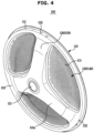
- FIG. 4 is a perspective view illustrating the drum back according to an embodiment
- FIG. 5 is a front view illustrating the drum back and the tub back according to an embodiment.
- the drum back 100 provided at the rear end of the drum 30 may be provided to block the rear end opening of the drum body 32.
- the drum back 100 may be provided to be inserted into the rear end opening of the drum body 32.
- the drum back 100 may include a first region 140 in which the plurality of holes 131 are formed, and a second region 150 correspondingly provided on which the shaft flange 60 is seated.
- the drum back 100 may include a drum back body 110 formed in a disc shape.
- the disc-shaped drum back body 110 may include a front surface 110a, and a rear surface 110b formed on the opposite side of the front surface 110a.
- the front surface 110a of the drum back body 110 may refer to a surface facing the inside of the drum 30, and the rear surface 110b of the drum back body 110 may refer to a surface facing the outside of the drum 30.
- the drum back 100 may include a plurality of recess portions 120, each corresponding to the plurality of flange portions 62 and formed to be recessed from the rear to the front, and an opening 130 formed between adjacent recess portions 120.
- the opening 130 may refer to the first region 140.
- the plurality of recess portions 120 may refer to the second region 150.
- the drum back body 110 may include the opening 130 in which the plurality of holes 131 are formed, and the recess portions 120 on which the shaft flange 60 is seated.
- the recess portion 120 may be provided at the center of the drum back body 110 to correspond to the flange shaft 60, respectively.
- the recess portion 120 may be provided in a plurality to correspond to the plurality of flange portions 62 of the flange shaft 60.
- the recess portions 120 may be formed to protrude toward a front side of the drum back body 110.
- a shaft support 121 may be formed at the center of the drum back body 110 to support the shaft 41.
- the shaft support 121 may be disposed at the center of the recess portions 120.
- the shaft support 121 may be located in the recess portion 120.
- the shaft support 121 may be located in the second region 150.
- a rim 111 may be provided on the drum back body 110 of the drum back 100.
- the rim 111 may be formed by bending from an outer end of the drum back body 110 to correspond to an inner diameter of the drum 30.
- the rim 111 of the drum back 100 may be provided with a shaft flange fixing portion 122.
- the shaft flange fixing portion 122 may be formed to correspond to the coupling holes 35 of the drum body 32.
- the shaft flange fixing portion 122 may be formed to correspond to the fastening holes 64 of the shaft flange 60.
- the shaft flange fixing portions 122 may be formed to be spaced apart in the circumferential direction.
- the shaft flange fixing portion 122 may be formed to correspond to the fastening holes 64 of the shaft flange 60 and the coupling holes 35 of the drum body 32, and may be fixed to each other through a faster (not shown).
- the openings 130 of the drum back 100 may include a portion except for the recess portions 120.
- the openings 130 may be formed between the plurality of recess portions 120 adjacent to each other.
- the plurality of holes 131 may be formed in the openings 130 of the drum back 100.
- the plurality of holes 131 may be formed in each opening 130 of the drum back 100.
- the opening 130 of the drum back 100 may be formed in three sections.
- the openings 130 of the drum back 100 may be formed at intervals of 120 degrees.
- the openings 130 of the drum back 100, i.e., the first region 140 may be formed to be spaced apart in the circumferential direction by the second region 150.
- the first region 140 of the drum back 100 may be formed at a predetermined interval by the recess portions 120 formed in the disc-shaped drum back body 110.
- the drum back 100 may be made of steel material.
- the drum back body 110 may be made of steel material.
- the recess portions 120 and the openings 130 of the drum back 100 may be formed integrally with a steel material.
- the first region 140 and the second region 150 of the drum back 100 may be formed integrally with a steel material.
- the plurality of holes 131 may be formed in the respective opening 130 of the drum back 100 at regular intervals.
- the openings 130 of the drum back 100 may be formed at a position corresponding to the exhaust port 220 of the tub 20.
- the openings 130 of the drum back 100 may be placed in communication with the exhaust port 220 of the tub 20.
- the area of the openings 130 of the drum back 100 may be formed to be larger than the area of the exhaust port 220 of the tub 20.
- the area of the exhaust port 220 of the tub 20 may be smaller than the area of the openings 130 of the drum back 100.
- air may move to the exhaust port 220 of the tub 20 through the plurality of holes 131 formed in the openings 130 of the drum back 100, thereby improving drying efficiency.
- the openings 130 of the drum back 100 may be positioned to correspond to the entire area of the exhaust port 220 of the tub 20, thereby improving fluid flow, i.e., a flow of air. Air discharged through the openings 130 of the drum back 100 may flow smoothly through the exhaust port 220 of the tub 20 without obstructing the flow.
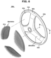
- FIG. 6 is a perspective view illustrating the rear surface of the drum of the washing machine according to an embodiment
- FIG. 7 is a cross-sectional view taken along line A-A' of FIG. 6 , showing the rear surface of the drum formed by a manufacturing method according to an embodiment.
- a first region 140A of a drum back 100A may include a porous plate 130A in which a plurality of holes 131A are formed.
- the drum back 100A may include a plurality of recess portions 120A, each corresponding to the plurality of flange portions 62 and formed to be recessed from the rear to the front, and an opening 113A formed between adjacent recess portions 120A.
- the opening 113A may refer to a first region 140A.
- the plurality of recess portions 120A may refer to a second region 150A.
- the drum back 100A may include a drum back body 110A having an opening 113A at least partially open in a disk shape, and the porous plate 130A provided to be coupled to the opening 113A of the drum back body 110A.
- the porous plate 130A may include a plate in which the plurality of holes 131A are formed.
- the porous plate 130A may be formed with the plurality of holes 131A spaced apart from each other at certain intervals.
- the porous plate 130A may form the first region 140A.
- the porous plate 130A of the drum back 100A may be coupled to the opening 113A of the drum back body 110A.
- the drum back body 110A of the drum back 100A may include a front surface 110Aa facing the inside of the drum 30 and a rear surface 110Ab formed on the opposite side of the front face 110Aa and facing the outside of the drum 30.
- the drum back body 110A may include a disc-shaped plate portion 112A and a rim 111A formed by bending an outer edge of the plate portion 112A.
- the rim 111A may be formed by bending from an outer end of the drum back body 110A to correspond to the inner diameter of the drum 30.
- a shaft flange fixing portion 122A may be formed on the rim 111A of the drum back 100A.
- the opening 113A of the drum back 100A may be formed by opening at least a portion of the drum back body 110A.
- the recess portion 120A for installing the flange shaft 60 may be provided in the plate portion 112A of the drum back body 110A.
- the recess portion 120A may be formed to correspond to the flange shaft 60.
- the recess portion 120A may be formed in a corresponding shape so that the flange shaft 60 may be seated thereon.
- the recess portion 120A may be formed to protrude toward the front of the plate portion 112A.
- the opening 113A may be provided in the plate portion 112A of the drum back body 110A so that the porous plate 130A may be coupled thereto.
- the opening 113A may be formed in a shape corresponding to the porous plate 130A.
- the opening 113A may be formed in three sections.
- the openings 113A may be formed at intervals of 120 degrees in the plate portion 112A of the drum back body 110A.
- the openings 113A may be formed to be spaced apart in the circumferential direction by the recess portions 120A.
- the opening 113A may be formed to be cut out of the plate portion 112A to allow the porous plate 130A to be installed.
- the drum back body 110 of the drum back 100 may be made of steel material.
- the plate portion 112A of the drum back body 110A may be made of steel material.
- the porous plate 130A may be made of steel.
- the porous plate 130A may be coupled to the opening 113A of the drum back body 110A by a seaming method. Seaming is a type of sealing method and may be mainly used for joints that require air-tightness and water-tightness.
- the porous plate 130A and the drum back body 110A may include a seaming portion 170A.
- the seaming portion 170A may include a first seaming portion 134A formed on the rim of the porous plate 130A, and a second seaming portion 114A formed on a porous plate installation portion of the plate portion 112A.
- the seaming portion 170A may be formed by bending the ends of the porous plate 130A and the opening 113A of the plate portion 112A by a predetermined length to bring the ends into contact with each other and joining the ends through a seaming process.
- the seaming portion 170A may be located on the rear surface 110Ab side of the drum back 100A.
- the seaming portion 170A may be located outside the drum 30.
- FIG. 8 is a perspective view illustrating the rear surface of the drum of the washing machine according to an embodiment
- FIG. 9 is a cross-sectional view of portion B-B' of FIG. 8 , showing the rear surface of the drum formed by a manufacturing method according to an embodiment.
- a first region 140B of the drum back 100B may include a porous plate 130B in which a plurality of holes 131B are formed.
- the drum back 100B may include a plurality of recess portions 120B, each corresponding to the plurality of flange portions 62 and formed to be recessed from the rear to the front, and an opening 113B formed between adjacent recess portions 120B.
- the opening 113B may correspond to the first region 140B.
- the plurality of recess portions 120B may correspond to a second region 150B.
- the drum back 100B may include a drum back body 110B formed in a disc- shape, and the porous plate 130B coupled to the drum back body 110B.
- the porous plate 130B may include a plate in which the plurality of holes 131B are formed.
- the porous plate 130B may be formed with the plurality of holes 131B spaced apart from each other at certain intervals.
- the porous plate 130B may form the first region 140B.
- the porous plate 130B may be formed in a shape corresponding to the opening 113B so that the porous plate 130B may be coupled to the opening 113B.
- the drum back body 110B of the drum back 100B may include a front surface 110Ba facing the inside of the drum 30 and a rear surface 110Bb formed on the opposite side of the front face 110Ba and facing the outside of the drum 30.
- the drum back body 110B may include a disk-shaped plate portion 112B and a rime 111B formed by bending an outer edge of the plate portion 112B.
- the rim 111B may be formed by bending from an outer end of the drum back body 110B to correspond to the inner diameter of the drum 30.
- the recess portion 120B for installing the flange shaft 60 may be provided in the plate portion 112B of the drum back body 110B.
- the recess portion 120B may be formed to correspond to the flange shaft 60.
- the recess portion 120B may be formed in a corresponding shape so that the flange portion 62 of the flange shaft 60 may be seated thereon.
- the plurality of recess portions 120B may be provided to correspond to the flange portions 62.
- the drum back body 110B of the drum back 100B may be formed of steel material.
- the plate portion 112B of the drum back body 110B may be formed of steel material.
- the porous plate 130B may be formed of a resin material.
- the porous plate 130B may be insert-molded into the opening 113B of the drum back body 110B.
- the opening 113B may be formed in the plate portion 112B of the drum back body 110B to allow the porous plate 130B to be coupled thereto.
- the opening 113B may be formed in three sections.
- the openings 113B may be formed at intervals of 120 degrees in the drum back body 110B.
- the three openings 113B may be formed spaced apart in the circumferential direction by the plurality of recess portions 120B.
- the porous plate 130B and the drum back body 110B may include a coupling portion 170B.
- the coupling portion 170B may be provided to connect the porous plate 130B and the drum back body 110B by insert injection.
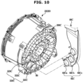
- FIG. 10 is a view illustrating a state before the drying duct is connected to the rear surface of the tub according to an embodiment
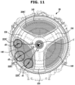
- FIG. 11 is a view illustrating the rear surface of the tub of the washing machine according to an embodiment.
- the tub 20 may include a tub back 200C forming a rear surface thereof.
- the tub back 200C may have an exhaust portion 220C formed at one lower side to which the exhaust duct 80 is connected.
- the exhaust portion 220C may be provided to connect the exhaust duct 80 and the tub 20.
- the exhaust portion 220C may include at least one or more exhaust port 221C, 222C, and 223C formed in the tub back 200C.
- the exhaust portion 220C may be formed with at least one to prevent problems that may occur when the flange shaft 60 coupled to the rotating drum 30 blocks the exhaust portion 220C formed in the tub back 200C.
- the exhaust portion 220C may be formed with at least one or more to prevent problems that may occur when the flange portion 62 of the flange shaft 60 coupled to the rear surface of the rotating drum 30 blocks the exhaust portion 220C of the tub back 200C.
- the flange shaft 60 fixed to the drum back 100 may rotate.
- the flange portion 62 of the flange shaft 60 may block the exhaust portion 220C located on the lower side of the tub 20 depending on a stopping position of the drum 30, thereby causing the obstruction to air flow.
- foreign substances such as lint may accumulate around the exhaust portion 220C located at the lower portion of the tub 20, which may block the flow path between the exhaust portion 220C and the exhaust duct 80, thereby causing the obstruction to air flow.
- the exhaust portion 220C of the tub back 200C may include the plurality of exhaust ports 221C, 222C, and 223C.
- the exhaust ports 221C, 222C, and 223C may include a first exhaust port 221C, a second exhaust port 222C, and a third exhaust port 223C.
- the first exhaust port 221C, the second exhaust port 222C, and the third exhaust port 223C may be positioned at different distances from the center C of the tub back 200C.
- the first exhaust port 221C, the second exhaust port 222C, and the third exhaust port 223C may each be positioned at different distances from the center of the rear surface of the tub 20.
- the first exhaust port 221C, the second exhaust port 222C, and the third exhaust port 223C may be positioned at different positions from the center C of the tub back 200C.
- the first exhaust port 221C, the second exhaust port 222C, and the third exhaust port 223C may be connected to the exhaust duct 80 at a plurality of different positions regardless of the position of the flange shaft 60 coupled to the drum 30, so that there is no obstruction to air flow to improve drying efficiency.
- At least a different one of the plurality of exhaust ports 221C, 222C, and 223C may be in a position not overlapping with any one of the plurality of flange portions 62.
- the first exhaust port 221C may be positioned on one lower side from the center C of the tub back 200C.
- the first exhaust port 221C may be formed at a first interval L1 from the center C of the tub back 200C.
- the second exhaust port 222C may be formed at a second interval L2 from the center C of the tub back 200C.
- the third exhaust port 223C may be formed at a third interval L3 from the center C of the tub back 200C.
- the first interval L1, the second interval L2, and the third interval L3 may have different lengths.
- the plurality of exhaust ports 221C, 222C, and 223C may have different widths. At least one of the plurality of exhaust ports 221C, 222C, and 223C may have a width different from that of another exhaust port.
- a first diameter d1 of the first exhaust port 221C, a second diameter d2 of the second exhaust port 222C, and a third diameter d3 of the third exhaust port 223C may be formed differently. As such, exhaust ports having different diameters and sizes and spaced at different intervals, may enable equivalent drying performance in different environments.
- the exhaust duct 80 may be provided with an exhaust connection portion 82C corresponding to the exhaust portion 220C of the tub back 200C.
- the exhaust portion connection portion 82C may be formed to correspond to the exhaust portion 220C.
- the corresponding sealing member 86 may be provided between the exhaust portion connection portion 82C and the exhaust portion 220C.
- the exhaust connection portion 82C may include a first connector 82Ca, a second connector 82Cb, and a third connector 82Cc.
- the first connector 82Ca may be connected to the first exhaust port 221C.
- the second connector 82Cb may be connected to the second exhaust port 222C.
- the third connector 82Cc may be connected to the third exhaust port 223C.
- the first connector 82Ca, the second connector 82Cb, and the third connector 82Cc may be formed at a position corresponding to the first exhaust port 221C, the second exhaust port 222C, and the third exhaust port 223C, respectively.
- the exhaust port of the tub back is illustrated as including three exhaust ports, but the spirit of the present disclosure is not limited thereto.
- the number of exhaust ports formed in the tub back may be varied in various ways.
- the number of exhaust port connectors of the exhaust duct connected to the exhaust port may be varied depending on the exhaust port.
- a exhaust port and a exhaust port connector are each shown as a circular shape, but the spirit of the present disclosure is not limited thereto.
- the connection hole and the connector may each include an oval shape, a square shape, or the like formed at corresponding positions.
Landscapes
- Engineering & Computer Science (AREA)
- Textile Engineering (AREA)
- Main Body Construction Of Washing Machines And Laundry Dryers (AREA)
Applications Claiming Priority (2)
| Application Number | Priority Date | Filing Date | Title |
|---|---|---|---|
| KR1020210141983A KR20230057787A (ko) | 2021-10-22 | 2021-10-22 | 세탁기 |
| PCT/KR2022/012578 WO2023068523A1 (fr) | 2021-10-22 | 2022-08-23 | Machine à laver |
Publications (2)
| Publication Number | Publication Date |
|---|---|
| EP4365366A1 true EP4365366A1 (fr) | 2024-05-08 |
| EP4365366A4 EP4365366A4 (fr) | 2024-10-16 |
Family
ID=86059374
Family Applications (1)
| Application Number | Title | Priority Date | Filing Date |
|---|---|---|---|
| EP22883749.8A Pending EP4365366A4 (fr) | 2021-10-22 | 2022-08-23 | Machine à laver |
Country Status (5)
| Country | Link |
|---|---|
| US (1) | US12595608B2 (fr) |
| EP (1) | EP4365366A4 (fr) |
| KR (1) | KR20230057787A (fr) |
| CN (1) | CN117897530A (fr) |
| WO (1) | WO2023068523A1 (fr) |
Families Citing this family (9)
| Publication number | Priority date | Publication date | Assignee | Title |
|---|---|---|---|---|
| EP4678804A1 (fr) * | 2023-06-30 | 2026-01-14 | Samsung Electronics Co., Ltd. | Appareil de traitement de vêtements |
| EP4692443A1 (fr) * | 2023-06-30 | 2026-02-11 | Samsung Electronics Co., Ltd. | Appareil d'entretien de vêtements |
| AU2024332280A1 (en) * | 2023-08-30 | 2025-10-09 | Lg Electronics Inc. | Clothes treatment apparatus |
| KR20250076315A (ko) * | 2023-11-22 | 2025-05-29 | 삼성전자주식회사 | 의류처리장치 |
| KR20250108447A (ko) * | 2024-01-08 | 2025-07-15 | 삼성전자주식회사 | 의류처리장치 |
| KR20250110070A (ko) * | 2024-01-11 | 2025-07-18 | 삼성전자주식회사 | 의류처리장치 |
| US20250230598A1 (en) * | 2024-01-11 | 2025-07-17 | Samsung Electronics Co., Ltd. | Clothes treating apparatus |
| WO2025187939A1 (fr) * | 2024-03-07 | 2025-09-12 | 삼성전자주식회사 | Appareil de traitement de vêtements et procédé de fabrication de cuve |
| WO2026000599A1 (fr) * | 2024-06-26 | 2026-01-02 | 无锡小天鹅电器有限公司 | Ensemble tambour de séchage de sèche-linge et sèche-linge |
Family Cites Families (54)
| Publication number | Priority date | Publication date | Assignee | Title |
|---|---|---|---|---|
| DE69426873T2 (de) | 1994-06-01 | 2001-12-13 | Solutia Europe N.V./S.A., Bruessel/Bruxelles | Verfahren und Vorrichtung zum Formen von Geschnitten, gekrümmten Rohlingen |
| KR0176507B1 (ko) | 1995-03-23 | 1999-05-01 | 김광호 | 캠코더용 회로기판을 검사-조정하는 시스템 |
| KR0158976B1 (ko) | 1995-06-16 | 1999-01-15 | 이형도 | 테이프 레코더의 백업용 드럼 |
| KR19980047548A (ko) | 1996-12-14 | 1998-09-15 | 박병재 | 브레이크 드럼 변형량 측정장치 |
| KR200180944Y1 (ko) | 1997-05-21 | 2000-05-15 | 박문규 | 차량용 드럼브레이크의 브레이크슈 간격조정장치 |
| JP3529606B2 (ja) | 1997-11-12 | 2004-05-24 | リンナイ株式会社 | 金属製ドラムの製造方法 |
| JPH11259834A (ja) | 1998-03-12 | 1999-09-24 | Sony Corp | 回転ドラム装置及び磁気記録再生装置 |
| JP2002230868A (ja) | 2001-01-29 | 2002-08-16 | Sony Corp | テープドライブ装置 |
| JP3955571B2 (ja) | 2002-01-11 | 2007-08-08 | エルジー エレクトロニクス インコーポレーテッド | 改善された凝縮ダクト構造を有する洗濯機及び乾燥機 |
| KR100441098B1 (ko) | 2002-01-17 | 2004-07-19 | 엘지전자 주식회사 | 건조겸용 드럼세탁기의 응축수 역류방지구조 |
| KR200272315Y1 (ko) | 2002-02-01 | 2002-04-17 | 주식회사 서림케미칼 | 포장용 비닐백 손잡이 제조용 융착드럼 |
| KR100428201B1 (ko) | 2002-04-29 | 2004-05-20 | (주) 평창정공 | 히터 부러싱 기계의 히팅 실린더 드럼 롤러 장치 |
| KR200284284Y1 (ko) | 2002-04-29 | 2002-08-03 | (주) 평창정공 | 히터 부러싱 기계의 히팅 실린더 드럼 롤러 장치 |
| KR100587298B1 (ko) | 2003-12-10 | 2006-06-08 | 엘지전자 주식회사 | 드럼세탁기용 아웃터로터형 모터의 스테이터 코어 및백요크 제조방법 |
| US7748139B2 (en) | 2003-12-22 | 2010-07-06 | Lg Electronics Inc. | Laundry dryer and drum supporting assembly thereof |
| KR101071817B1 (ko) | 2004-04-19 | 2011-10-11 | 엘지전자 주식회사 | 건조겸용 드럼세탁기 |
| KR20050101740A (ko) * | 2004-04-20 | 2005-10-25 | 엘지전자 주식회사 | 건조겸용 드럼세탁기 |
| KR200358900Y1 (ko) | 2004-05-15 | 2004-08-12 | 엘지전자 주식회사 | 드럼 세탁기의 드럼 백 |
| KR100657465B1 (ko) | 2004-05-15 | 2006-12-13 | 엘지전자 주식회사 | 세탁기의 드럼 제작 방법 |
| US20050252252A1 (en) | 2004-05-15 | 2005-11-17 | Lg Electronics Inc. | Drum for washing machine |
| KR101093878B1 (ko) | 2004-06-05 | 2011-12-13 | 엘지전자 주식회사 | 건조기의 드럼 장치 |
| KR20060012493A (ko) | 2004-08-03 | 2006-02-08 | 한국델파이주식회사 | 차량용 드럼 브레이크의 웨브 지지형 백 플레이트 |
| KR100598000B1 (ko) | 2004-09-01 | 2006-07-13 | 엘지전자 주식회사 | 드럼 세탁기의 드럼 백 |
| KR100680203B1 (ko) | 2004-10-25 | 2007-02-08 | 엘지전자 주식회사 | 하측 개방형 전후 이동 도어를 갖는 세탁물 처리 장치 |
| DE102005004628A1 (de) | 2005-01-27 | 2006-08-17 | Siemens Ag | Mittelspannungslandanschluss für Schiffe |
| KR100686017B1 (ko) * | 2005-05-11 | 2007-02-26 | 엘지전자 주식회사 | 세탁기 |
| KR101275198B1 (ko) | 2005-05-23 | 2013-06-18 | 엘지전자 주식회사 | 드럼세탁기 및 그에 적용되는 드럼 제조방법 |
| JP4679352B2 (ja) * | 2005-11-25 | 2011-04-27 | 株式会社東芝 | 衣類乾燥機 |
| KR100669180B1 (ko) | 2005-12-19 | 2007-01-16 | 주식회사 대우일렉트로닉스 | 드럼세탁기에서 back-emf를 이용한 언밸런스 감지방법 |
| KR101056070B1 (ko) | 2005-12-28 | 2011-08-11 | 주식회사 만도 | 드럼 브레이크 |
| KR101210220B1 (ko) | 2006-12-06 | 2012-12-07 | 현대자동차주식회사 | 드럼 타입 시트 백 리클라이너 |
| KR20090012766A (ko) | 2007-07-31 | 2009-02-04 | 주식회사 만도 | 주차 브레이크용 백플레이트의 내구성 향상 구조 |
| JP4603064B2 (ja) * | 2008-07-04 | 2010-12-22 | パナソニック株式会社 | ドラム式洗濯乾燥機 |
| KR20100129156A (ko) | 2009-05-28 | 2010-12-08 | 엘지전자 주식회사 | 세탁장치 |
| KR101417778B1 (ko) * | 2009-08-24 | 2014-07-09 | 삼성전자 주식회사 | 세탁기, 세탁기의 이너터브 및 그 조립방법 |
| KR101631545B1 (ko) * | 2009-12-02 | 2016-06-24 | 삼성전자 주식회사 | 드럼 및 이를 가지는 드럼세탁기 |
| KR20120040379A (ko) * | 2010-10-19 | 2012-04-27 | 엘지전자 주식회사 | 건조겸용 세탁장치 |
| KR20120045612A (ko) | 2010-10-29 | 2012-05-09 | 서용우 | 드럼 브레이크용 백 플레이트 제조방법 |
| WO2013058698A1 (fr) | 2011-10-17 | 2013-04-25 | Shl Group Ab | Dispositif d'administration de médicament |
| KR101951423B1 (ko) * | 2012-10-09 | 2019-04-25 | 엘지전자 주식회사 | 듀얼드럼 세탁기의 서브드럼 구조 및 이를 이용한 서브드럼 결합방법 |
| KR20140019553A (ko) | 2012-08-06 | 2014-02-17 | 동부대우전자 주식회사 | 드럼세탁기의 거품 역류 방지 방법 및 그 장치 |
| KR200474446Y1 (ko) | 2013-03-13 | 2014-09-17 | 한국수력원자력 주식회사 | 부풀음 방지가 가능한 방사성폐기물드럼 |
| KR101528062B1 (ko) | 2013-12-09 | 2015-06-10 | 이시우 | 심부시추용 전기다운홀모터에 전력을 공급하는 전력케이블 설치시스템 및 방법 |
| FR3017072B1 (fr) | 2014-01-31 | 2016-02-19 | Toray Films Europ | Film de polyester transparent multicouche, son procede de fabrication et son utilisation notamment dans les faces arrieres de panneaux photovoltaiques |
| CN105525481B (zh) * | 2014-09-29 | 2019-10-01 | 青岛海尔滚筒洗衣机有限公司 | 一种自清洁滚筒洗衣机 |
| KR20160092814A (ko) | 2015-01-28 | 2016-08-05 | 주식회사 만도 | 드럼 브레이크의 백플레이트 및 그의 성형 방법 |
| JP5922829B2 (ja) | 2015-06-10 | 2016-05-24 | 日立アプライアンス株式会社 | ドラム式の洗濯機または洗濯乾燥機 |
| US10849613B2 (en) | 2015-09-24 | 2020-12-01 | Mininvasive Ltd. | Arthroscopic surgical device |
| WO2018021871A1 (fr) * | 2016-07-28 | 2018-02-01 | 삼성전자주식회사 | Machine à laver |
| JP2019017532A (ja) | 2017-07-13 | 2019-02-07 | 三星電子株式会社Samsung Electronics Co.,Ltd. | 洗濯乾燥機 |
| KR102598156B1 (ko) | 2016-10-10 | 2023-11-06 | 삼성전자주식회사 | 세탁기 |
| KR102375813B1 (ko) | 2017-03-06 | 2022-03-17 | 삼성전자주식회사 | 세탁기 |
| KR101937047B1 (ko) | 2017-09-12 | 2019-01-09 | 두산중공업 주식회사 | 발전소 전기설계 물량 관리 시스템 및 그 방법 |
| JP7269703B2 (ja) * | 2018-05-01 | 2023-05-09 | 青島海爾洗衣机有限公司 | 洗濯乾燥機 |
-
2021
- 2021-10-22 KR KR1020210141983A patent/KR20230057787A/ko active Pending
-
2022
- 2022-08-23 WO PCT/KR2022/012578 patent/WO2023068523A1/fr not_active Ceased
- 2022-08-23 CN CN202280056710.9A patent/CN117897530A/zh active Pending
- 2022-08-23 EP EP22883749.8A patent/EP4365366A4/fr active Pending
-
2024
- 2024-01-31 US US18/428,215 patent/US12595608B2/en active Active
Also Published As
| Publication number | Publication date |
|---|---|
| EP4365366A4 (fr) | 2024-10-16 |
| US12595608B2 (en) | 2026-04-07 |
| US20240167208A1 (en) | 2024-05-23 |
| KR20230057787A (ko) | 2023-05-02 |
| CN117897530A (zh) | 2024-04-16 |
| WO2023068523A1 (fr) | 2023-04-27 |
Similar Documents
| Publication | Publication Date | Title |
|---|---|---|
| EP4365366A1 (fr) | Machine à laver | |
| EP1118703B1 (fr) | Machine a laver a tambour | |
| KR20210061985A (ko) | 의류처리장치 | |
| EP1975298A1 (fr) | Machine à laver | |
| CN103132278B (zh) | 洗衣机 | |
| KR102017530B1 (ko) | 리프터와 이를 가지는 건조기 | |
| CN103726267A (zh) | 洗衣机 | |
| EP4227458A1 (fr) | Appareil de traitement de vêtements | |
| WO2014024393A1 (fr) | Sèche-linge | |
| EP1650338A2 (fr) | Machine à laver séchante. | |
| EP4039873B1 (fr) | Appareil de traitement du linge | |
| JP4490251B2 (ja) | 乾燥機兼用洗濯機 | |
| EP1584732B1 (fr) | Sèche-linge | |
| AU2016206404B2 (en) | Washing and/or drying appliance | |
| KR20190000515A (ko) | 의류 건조기 | |
| JP2011167425A (ja) | 乾燥装置 | |
| EP4047123B1 (fr) | Appareil de traitement du linge | |
| EP3875663B1 (fr) | Appareil de traitement du linge | |
| EP3674474B1 (fr) | Appareil de traitement du linge | |
| KR20230111118A (ko) | 의류처리장치 및 의류처리장치 제어방법 | |
| KR20230111116A (ko) | 의류처리장치 | |
| EP1795641A1 (fr) | Machine à laver le linge à usage domestique avec moteur d'entrainement compact | |
| KR20180097389A (ko) | 임펠러 및 이를 가지는 의류처리장치용 배수펌프 | |
| CN101076631B (zh) | 洗衣机马达 | |
| KR102847243B1 (ko) | 의류처리장치 및 의류처리장치의 제어방법 |
Legal Events
| Date | Code | Title | Description |
|---|---|---|---|
| STAA | Information on the status of an ep patent application or granted ep patent |
Free format text: STATUS: THE INTERNATIONAL PUBLICATION HAS BEEN MADE |
|
| PUAI | Public reference made under article 153(3) epc to a published international application that has entered the european phase |
Free format text: ORIGINAL CODE: 0009012 |
|
| STAA | Information on the status of an ep patent application or granted ep patent |
Free format text: STATUS: REQUEST FOR EXAMINATION WAS MADE |
|
| 17P | Request for examination filed |
Effective date: 20240131 |
|
| AK | Designated contracting states |
Kind code of ref document: A1 Designated state(s): AL AT BE BG CH CY CZ DE DK EE ES FI FR GB GR HR HU IE IS IT LI LT LU LV MC MK MT NL NO PL PT RO RS SE SI SK SM TR |
|
| REG | Reference to a national code |
Ref country code: DE Ref legal event code: R079 Free format text: PREVIOUS MAIN CLASS: D06F0058060000 Ipc: D06F0025000000 |
|
| A4 | Supplementary search report drawn up and despatched |
Effective date: 20240916 |
|
| RIC1 | Information provided on ipc code assigned before grant |
Ipc: D06F 58/02 20060101ALI20240910BHEP Ipc: D06F 37/26 20060101ALI20240910BHEP Ipc: D06F 37/04 20060101ALI20240910BHEP Ipc: D06F 25/00 20060101AFI20240910BHEP |
|
| DAV | Request for validation of the european patent (deleted) | ||
| DAX | Request for extension of the european patent (deleted) | ||
| GRAP | Despatch of communication of intention to grant a patent |
Free format text: ORIGINAL CODE: EPIDOSNIGR1 |
|
| STAA | Information on the status of an ep patent application or granted ep patent |
Free format text: STATUS: GRANT OF PATENT IS INTENDED |
|
| INTG | Intention to grant announced |
Effective date: 20260306 |