EP4365384A1 - Dispositif de fixation, unité de montage et procédé de montage d'une vis à tête de marteau sur un rail d'ancrage - Google Patents
Dispositif de fixation, unité de montage et procédé de montage d'une vis à tête de marteau sur un rail d'ancrage Download PDFInfo
- Publication number
- EP4365384A1 EP4365384A1 EP24165013.4A EP24165013A EP4365384A1 EP 4365384 A1 EP4365384 A1 EP 4365384A1 EP 24165013 A EP24165013 A EP 24165013A EP 4365384 A1 EP4365384 A1 EP 4365384A1
- Authority
- EP
- European Patent Office
- Prior art keywords
- hammer head
- head screw
- anchor rail
- holding plate
- fastening device
- Prior art date
- Legal status (The legal status is an assumption and is not a legal conclusion. Google has not performed a legal analysis and makes no representation as to the accuracy of the status listed.)
- Granted
Links
Images

Classifications
-
- E—FIXED CONSTRUCTIONS
- E04—BUILDING
- E04B—GENERAL BUILDING CONSTRUCTIONS; WALLS, e.g. PARTITIONS; ROOFS; FLOORS; CEILINGS; INSULATION OR OTHER PROTECTION OF BUILDINGS
- E04B1/00—Constructions in general; Structures which are not restricted either to walls, e.g. partitions, or floors or ceilings or roofs
- E04B1/38—Connections for building structures in general
- E04B1/41—Connecting devices specially adapted for embedding in concrete or masonry
- E04B1/4107—Longitudinal elements having an open profile, with the opening parallel to the concrete or masonry surface, i.e. anchoring rails
-
- F—MECHANICAL ENGINEERING; LIGHTING; HEATING; WEAPONS; BLASTING
- F16—ENGINEERING ELEMENTS AND UNITS; GENERAL MEASURES FOR PRODUCING AND MAINTAINING EFFECTIVE FUNCTIONING OF MACHINES OR INSTALLATIONS; THERMAL INSULATION IN GENERAL
- F16B—DEVICES FOR FASTENING OR SECURING CONSTRUCTIONAL ELEMENTS OR MACHINE PARTS TOGETHER, e.g. NAILS, BOLTS, CIRCLIPS, CLAMPS, CLIPS OR WEDGES; JOINTS OR JOINTING
- F16B37/00—Nuts or like thread-engaging members
- F16B37/04—Devices for fastening nuts to surfaces, e.g. sheets, plates
- F16B37/045—Devices for fastening nuts to surfaces, e.g. sheets, plates specially adapted for fastening in channels, e.g. sliding bolts, channel nuts
-
- F—MECHANICAL ENGINEERING; LIGHTING; HEATING; WEAPONS; BLASTING
- F16—ENGINEERING ELEMENTS AND UNITS; GENERAL MEASURES FOR PRODUCING AND MAINTAINING EFFECTIVE FUNCTIONING OF MACHINES OR INSTALLATIONS; THERMAL INSULATION IN GENERAL
- F16B—DEVICES FOR FASTENING OR SECURING CONSTRUCTIONAL ELEMENTS OR MACHINE PARTS TOGETHER, e.g. NAILS, BOLTS, CIRCLIPS, CLAMPS, CLIPS OR WEDGES; JOINTS OR JOINTING
- F16B37/00—Nuts or like thread-engaging members
- F16B37/08—Quickly-detachable or mountable nuts, e.g. consisting of two or more parts; Nuts movable along the bolt after tilting the nut
- F16B37/0807—Nuts engaged from the end of the bolt, e.g. axially slidable nuts
- F16B37/0857—Nuts engaged from the end of the bolt, e.g. axially slidable nuts with the threaded portions of the nut engaging the thread of the bolt by the action of one or more springs or resilient retaining members
Definitions
- the present invention relates to a fastening device for an anchor rail with a hammer head screw and a holding plate fixed to the hammer head screw, a plurality of teeth for engagement with a toothing on the anchor rail, and an opening through which a threaded bolt of the hammer head screw is passed, wherein at least one locking web (25) protruding into the opening of the holding plate is provided on the holding plate, by means of which the holding plate can be locked to the threaded bolt of the hammer head screw, wherein the at least one locking web is formed integrally with a plate-shaped locking element with an opening for passing through the threaded bolt of the hammer head screw, an assembly unit and a method for mounting a hammer head screw on an anchor rail.
- the EN 10 2009 032 032 A1 discloses a hammer head screw for mounting on an anchor rail, in which a plate-shaped toothed part is placed on the hammer head screw, which engages with a toothing of an anchor rail.
- the toothed part has a through hole into which the screw shaft is inserted in order to then mount the hammer head screw with the toothed part on the anchor rail.
- a strip made of an elastic foam material can be arranged in the anchor rail so that the head of the hammer head screw is pressed against the inwardly projecting webs on the anchor rail. If the elastic strip is removed from the anchor rail, however, the hammer head screw with the toothed part can sink into the anchor rail and then fall down, which makes assembly more difficult, especially if the toothed part and hammer head screw separate from each other again.
- CN 202 466 908 U discloses a fastening device with an anchor rail to which an anchor head screw with a profile on a screw head can be fixed. A threaded section of the hammer head screw is passed through a locking device.
- the fastening device comprises a hammer head screw and a retaining plate fixed to the hammer head screw with several teeth for engagement with a toothing on an anchor rail and an opening through which a threaded bolt of the hammer head screw passes, wherein at least one locking web is provided which projects into the opening of the retaining plate and by means of which the retaining plate can be locked onto the threaded bolt of the hammer head screw.
- the retaining plate and hammer head screw thus form a lockable unit which can be more easily mounted on an anchor rail.
- the locking web uses the profiling of the threaded bolt by forming the individual threads to create a locking connection between the retaining plate and the hammer head screw.
- locking bars are provided on the opening of the retaining plate, distributed around the circumference.
- three to five locking bars can be used to lock the retaining plate onto the threaded bolt.
- the locking webs are integrally formed with a plate-shaped locking element with an opening for the threaded bolt to pass through.
- the locking element is glued or welded to the retaining plate, in particular on the side of the retaining plate facing away from the head of the hammer head screw. This allows the retaining plate to be mounted with the locking element as a unit.
- the retaining plate is preferably at least twice as thick as the plate-shaped locking element, in particular four or eight times as thick. While the locking element can be very thin, in particular so that the locking bars are resilient and have a certain degree of flexibility, forces from the anchor rail are to be transmitted via the retaining plate, so that it is designed to be significantly thicker.
- the locking element can, for example, be made of a thin sheet metal or a plastic plate.
- the holding plate can be made of a thicker sheet metal.
- the retaining plate preferably has teeth on opposite sides, which are at least partially covered by a projection. This allows the retaining plate to be placed on the anchor rail so that the teeth engage with the teeth on the anchor rail, with the projection limiting movement of the retaining plate in the axial direction of the threaded bolt.
- the projection can be formed integrally with the locking element so that positioning on the anchor rail can be carried out via the locking element.
- the projection can be formed as a bendable web, which is optionally inclined to the plane of the plate-shaped locking element, for example at an angle between 2° and 20°.
- the retaining plate is preferably thinner than a sheet of the anchor rail on which the teeth are formed. This ensures that a component is clamped to the anchor rail and that the retaining plate does not hinder this clamping.
- a holding plate with several teeth for engagement with a toothing on an anchor rail is first placed on a threaded bolt of a hammer head screw and then pushed linearly onto the threaded bolt, with at least one locking web being guided in a locking manner on the threaded bolt.
- the locking web has a certain elasticity in order to lock onto the individual threads, but can be pushed linearly onto the threaded bolt by applying a certain amount of pressure. This eliminates the need to unscrew the holding plate, which would be necessary if the holding plate had an internal thread.
- the unit consisting of hammer head screw and holding plate is then placed on an anchor rail, with the teeth of the holder engaging with the toothing so that the hammer head screw can then be turned before a component is fixed to the threaded bolt of the hammer head screw.
- An anchor rail 1 is designed in the form of a strip and comprises a plurality of anchor webs 2 which are integrally formed with a first rail part 3a and a second rail part 3b.
- the two rail parts 3a and 3b are connected to one another via connecting webs 4 and have a toothing 5 on the side facing one another, spaced apart from the connecting webs 4.
- a cavity is formed between the toothing 5 and the connecting webs 4 in order to mount hammer head screws 10.
- the anchor rail 1 can be designed as shown in detail in the EN 10 2019 106 155 which is hereby incorporated by reference.
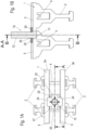
- a fastening device for fixing to the anchor rail 1 comprises a hammer head screw 10, which has a substantially cuboid-shaped head 11 and a threaded bolt 12.
- the head 11 of the hammer head screw 10 engages behind the strip-shaped webs on the rail parts 3a and 3b, on each of which a toothing 5 with a plurality of teeth is formed.
- a holding plate 20 is provided, which is placed on the threaded bolt 12 of the hammer head screw 10.
- the holding plate 20 comprises a plurality of teeth 27 on two opposite sides, which engage with the toothing 5 on the anchor rail 1.
- a plate-shaped locking element 22 is also fixed to the holding plate 20, which comprises projections 24 that rest on the webs with the toothing 5. This prevents the holding plate 20 from entering the cavity between the connecting web 4 and the toothing 5 and the teeth 27 from remaining in engagement with the toothing 5.
- the projections 24 are formed on opposite sides of the locking element 22.
- the locking element 22 can be glued or welded to the holding plate 20.
- the holding plate 20 also comprises inwardly projecting locking webs 25 that can be locked onto the threads of the threaded bolt 12.
- the hammer head screw 10 is thus pre-fixed to the anchor rail 1 via the holding plate 20 and the locking element 22.
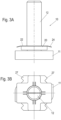
- the holding plate 20 with the plate-shaped locking element 22 is shown in detail. It can be seen that the plate-shaped locking element 22 is significantly thinner than the holding plate 20, for example the thickness of the plate-shaped locking element 22 is only between 5% and 25% of the thickness of the holding plate 20.
- the locking element 22 can be made from a thin sheet and welded to the holding plate 20. If the locking element 22 is made from plastic, it can also be glued.
- the projections 24 are aligned at an angle to the plane formed by the plate-shaped locking element 22, for example at an angle between 2° and 20°, in particular between 5° and 15°. This allows the projections 24 to be bent when the hammer head screw 10 is mounted, so that in the mounted position a head 11 of the hammer head screw 10 rests against the webs of the anchor rail 1 via the projections 24 and is thus pre-fixed.
- the holding plate 20 comprises a cylindrical opening 21, and the locking element 22 comprises an opening 23 which is essentially congruent with the opening 21, with a plurality of locking webs 25 projecting into the opening 23 on the locking element 22 distributed over the circumference.
- the distance from a tip of the locking webs 25 to a center of the opening 23 is thus less than the radius of the opening 23.
- the locking webs 25 are designed to be bendable and are arranged laterally spaced from the locking element 22 via slots 26, with the locking webs 25 being integrally connected to the locking element 22 in the longitudinal direction. In the illustrated embodiment, four locking webs 25 are provided, although the number of locking webs 25 can also be varied.
- the fastening device with the hammer head screw 10 and the holding plate 20 is shown.
- the holding plate 20 with the locking element 22 is first positioned at a tip of the threaded bolt 12 and then pushed linearly onto the threaded bolt, whereby the locking webs 25 along the threaded bolt are guided in a locking manner, ie they can be locked into the individual threads depending on how far the retaining plate 20 is pushed on.
- the retaining plate 20 is preferably pushed on up to the head 11 or just before it.
- the assembly unit can now be mounted on the anchor rail 1, which is preferably cast in concrete, by inserting the head 11 into the gap between the two toothings 5 and bringing the teeth 27 into engagement with the toothing 5.
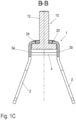
- the threaded bolt 12 can then be pressed slightly in the direction of the anchor rail 1, causing the projections 24 to bend, in order to then rotate the head 11 of the hammer head screw 10 so that the head engages behind the two webs with the toothing 5, as shown in Figure 1C is shown.
- the projections 24 press the head 11 onto the underside of the webs so that the assembly unit is clamped to the anchor rail 1.
- the anchor rail 1 In the assembled position, i.e. cast in a concrete component, the anchor rail 1 can be aligned horizontally, vertically or inclined in the longitudinal direction.
- the fastening device with the hammer head screw 10 and the holding plate 20 ensures pre-fixing for each orientation of the anchor rail 1.
- the holding plate 20, in particular the projections 24, reliably prevent the holding plate 20 from being pushed through the teeth 5 on the anchor rail 1.
- the length of the anchor rail 1 and the number of fastening devices per anchor rail 1 can be designed by the specialist depending on the requirements.
Landscapes
- Engineering & Computer Science (AREA)
- General Engineering & Computer Science (AREA)
- Mechanical Engineering (AREA)
- Architecture (AREA)
- Physics & Mathematics (AREA)
- Electromagnetism (AREA)
- Civil Engineering (AREA)
- Structural Engineering (AREA)
- Connection Of Plates (AREA)
- Joining Of Building Structures In Genera (AREA)
Applications Claiming Priority (3)
| Application Number | Priority Date | Filing Date | Title |
|---|---|---|---|
| DE102020102977.2A DE102020102977A1 (de) | 2020-02-05 | 2020-02-05 | Befestigungsvorrichtung, Montageeinheit und Verfahren zur Montage einer Hammerkopfschraube an einer Ankerschiene |
| PCT/EP2021/050423 WO2021156020A1 (fr) | 2020-02-05 | 2021-01-12 | Dispositif de fixation, unité d'installation et procédé d'installation d'un boulon à tête rectangulaire sur un rail d'ancrage |
| EP21700847.3A EP4100586B1 (fr) | 2020-02-05 | 2021-01-12 | Dispositif de fixation, unité d'installation et procédé d'installation d'un boulon à tête rectangulaire sur un rail d'ancrage |
Related Parent Applications (2)
| Application Number | Title | Priority Date | Filing Date |
|---|---|---|---|
| EP21700847.3A Division-Into EP4100586B1 (fr) | 2020-02-05 | 2021-01-12 | Dispositif de fixation, unité d'installation et procédé d'installation d'un boulon à tête rectangulaire sur un rail d'ancrage |
| EP21700847.3A Division EP4100586B1 (fr) | 2020-02-05 | 2021-01-12 | Dispositif de fixation, unité d'installation et procédé d'installation d'un boulon à tête rectangulaire sur un rail d'ancrage |
Publications (3)
| Publication Number | Publication Date |
|---|---|
| EP4365384A1 true EP4365384A1 (fr) | 2024-05-08 |
| EP4365384C0 EP4365384C0 (fr) | 2025-05-28 |
| EP4365384B1 EP4365384B1 (fr) | 2025-05-28 |
Family
ID=74191714
Family Applications (2)
| Application Number | Title | Priority Date | Filing Date |
|---|---|---|---|
| EP21700847.3A Active EP4100586B1 (fr) | 2020-02-05 | 2021-01-12 | Dispositif de fixation, unité d'installation et procédé d'installation d'un boulon à tête rectangulaire sur un rail d'ancrage |
| EP24165013.4A Active EP4365384B1 (fr) | 2020-02-05 | 2021-01-12 | Dispositif de fixation, unité de montage et procédé de montage d'une vis à tête de marteau sur un rail d'ancrage |
Family Applications Before (1)
| Application Number | Title | Priority Date | Filing Date |
|---|---|---|---|
| EP21700847.3A Active EP4100586B1 (fr) | 2020-02-05 | 2021-01-12 | Dispositif de fixation, unité d'installation et procédé d'installation d'un boulon à tête rectangulaire sur un rail d'ancrage |
Country Status (3)
| Country | Link |
|---|---|
| EP (2) | EP4100586B1 (fr) |
| DE (1) | DE102020102977A1 (fr) |
| WO (1) | WO2021156020A1 (fr) |
Families Citing this family (3)
| Publication number | Priority date | Publication date | Assignee | Title |
|---|---|---|---|---|
| DE102020120750A1 (de) | 2020-08-06 | 2022-02-10 | Wilhelm Modersohn Gmbh & Co Kg | Ankerschiene und Verfahren zur Herstellung einer Ankerschiene |
| DE102020122346A1 (de) | 2020-08-26 | 2022-03-03 | Wilhelm Modersohn Gmbh & Co Kg | Verankerungselement und Verfahren zur Montage eines Verankerungselementes |
| DE102022101225A1 (de) | 2022-01-19 | 2023-07-20 | Wilhelm Modersohn Gmbh & Co Kg | Befestigungsvorrichtung, Verfahren zur Montage einer Ankerschiene in einem Baukörper und Baukörper |
Citations (6)
| Publication number | Priority date | Publication date | Assignee | Title |
|---|---|---|---|---|
| DE19705709A1 (de) | 1997-02-14 | 1998-08-20 | Diag Design Ag | Verankerungseinheit zur Befestigung von Rohren oder dergleichen Gegenständen |
| DE102009032032A1 (de) | 2009-05-19 | 2011-02-03 | Wilhelm Modersohn Gmbh & Co Kg | Hammerkopfschraube |
| DE202007019242U1 (de) | 2007-12-06 | 2011-05-12 | Vm Edelstahltechnik Gmbh | Anordnung zur Lagesicherung einer Befestigungsschraube an einer Profilschiene sowie Bauteil hierfür |
| CN202466908U (zh) | 2012-02-29 | 2012-10-03 | 福建鹏坤实业有限公司 | 石材幕墙便捷销扣 |
| CN108086484A (zh) | 2017-12-26 | 2018-05-29 | 洛阳固岳轨道科技有限公司 | 一种防滑槽式预埋件 |
| DE102019106155A1 (de) | 2019-03-11 | 2020-09-17 | Wilhelm Modersohn Gmbh & Co Kg | Ankerschiene |
-
2020
- 2020-02-05 DE DE102020102977.2A patent/DE102020102977A1/de not_active Withdrawn
-
2021
- 2021-01-12 WO PCT/EP2021/050423 patent/WO2021156020A1/fr not_active Ceased
- 2021-01-12 EP EP21700847.3A patent/EP4100586B1/fr active Active
- 2021-01-12 EP EP24165013.4A patent/EP4365384B1/fr active Active
Patent Citations (6)
| Publication number | Priority date | Publication date | Assignee | Title |
|---|---|---|---|---|
| DE19705709A1 (de) | 1997-02-14 | 1998-08-20 | Diag Design Ag | Verankerungseinheit zur Befestigung von Rohren oder dergleichen Gegenständen |
| DE202007019242U1 (de) | 2007-12-06 | 2011-05-12 | Vm Edelstahltechnik Gmbh | Anordnung zur Lagesicherung einer Befestigungsschraube an einer Profilschiene sowie Bauteil hierfür |
| DE102009032032A1 (de) | 2009-05-19 | 2011-02-03 | Wilhelm Modersohn Gmbh & Co Kg | Hammerkopfschraube |
| CN202466908U (zh) | 2012-02-29 | 2012-10-03 | 福建鹏坤实业有限公司 | 石材幕墙便捷销扣 |
| CN108086484A (zh) | 2017-12-26 | 2018-05-29 | 洛阳固岳轨道科技有限公司 | 一种防滑槽式预埋件 |
| DE102019106155A1 (de) | 2019-03-11 | 2020-09-17 | Wilhelm Modersohn Gmbh & Co Kg | Ankerschiene |
Also Published As
| Publication number | Publication date |
|---|---|
| EP4365384C0 (fr) | 2025-05-28 |
| EP4100586B1 (fr) | 2024-05-01 |
| EP4100586A1 (fr) | 2022-12-14 |
| DE102020102977A1 (de) | 2021-08-05 |
| EP4365384B1 (fr) | 2025-05-28 |
| WO2021156020A1 (fr) | 2021-08-12 |
Similar Documents
| Publication | Publication Date | Title |
|---|---|---|
| EP2662645A2 (fr) | Support de module solaire | |
| EP4100586B1 (fr) | Dispositif de fixation, unité d'installation et procédé d'installation d'un boulon à tête rectangulaire sur un rail d'ancrage | |
| EP3649353B1 (fr) | Système de fixation | |
| EP2330261A1 (fr) | Dispositif d'ajustement de carrelages | |
| DE60302284T2 (de) | Schneideinsatz für Schrauben | |
| DE202006007821U1 (de) | Spann- oder Führungsschiene mit Verliersicherung für Haltebolzen | |
| DE202007001705U1 (de) | Verstellbare Halterung für Rohrmotoren | |
| AT406594B (de) | Montagesystem zur halterung von verkleidungselementen an bauwerken | |
| DE2215707C3 (de) | Klemmeinrichtung | |
| DE202014006758U1 (de) | Verbindungslasche | |
| DE102013105257B4 (de) | Doppelkeil zum Rahmensetzen | |
| DE202007019242U1 (de) | Anordnung zur Lagesicherung einer Befestigungsschraube an einer Profilschiene sowie Bauteil hierfür | |
| EP1775482A1 (fr) | Elément de fixation rapide | |
| EP4083448A1 (fr) | Fermoir actionné par curseur et rail de montage pourvu de fermoir actionné par curseur | |
| AT525006A1 (de) | Montageprofil | |
| DE102009040131B3 (de) | Befestigungslasche für ein Schutzzaunfeld | |
| DE29824254U1 (de) | Befestigungsvorrichtung | |
| DE102006022890A1 (de) | Befestigungssystem mit einem Clip | |
| DE102014009000B3 (de) | Zweiteiliges Befestigungselement für einen mit einem Ankerkopf versehenen Anker | |
| DE102014018920B4 (de) | Verbindereinrichtung für Profilstäbe | |
| AT525700B1 (de) | Verbindungsanordnung und Profilverbindungsanordnung | |
| EP4151865B1 (fr) | Système de connecteur | |
| EP4003893B1 (fr) | Dispositif de fixation permettant de fixer une position d'une console d'angle d'un seuil de porte d'une cage d'ascenseur, console d'angle équipée d'un tel dispositif de fixation et plaque de fixation, ainsi que procédé de mise à niveau d'une telle plaque de fixation | |
| EP1710193B1 (fr) | Dispositif de fixation pour les rails de guidages d'ascenseurs | |
| EP1593786B1 (fr) | Dispositif de fixation pour éléments dans plaques de travail |
Legal Events
| Date | Code | Title | Description |
|---|---|---|---|
| PUAI | Public reference made under article 153(3) epc to a published international application that has entered the european phase |
Free format text: ORIGINAL CODE: 0009012 |
|
| STAA | Information on the status of an ep patent application or granted ep patent |
Free format text: STATUS: THE APPLICATION HAS BEEN PUBLISHED |
|
| AC | Divisional application: reference to earlier application |
Ref document number: 4100586 Country of ref document: EP Kind code of ref document: P |
|
| AK | Designated contracting states |
Kind code of ref document: A1 Designated state(s): AL AT BE BG CH CY CZ DE DK EE ES FI FR GB GR HR HU IE IS IT LI LT LU LV MC MK MT NL NO PL PT RO RS SE SI SK SM TR |
|
| STAA | Information on the status of an ep patent application or granted ep patent |
Free format text: STATUS: REQUEST FOR EXAMINATION WAS MADE |
|
| 17P | Request for examination filed |
Effective date: 20241106 |
|
| RBV | Designated contracting states (corrected) |
Designated state(s): AL AT BE BG CH CY CZ DE DK EE ES FI FR GB GR HR HU IE IS IT LI LT LU LV MC MK MT NL NO PL PT RO RS SE SI SK SM TR |
|
| GRAP | Despatch of communication of intention to grant a patent |
Free format text: ORIGINAL CODE: EPIDOSNIGR1 |
|
| STAA | Information on the status of an ep patent application or granted ep patent |
Free format text: STATUS: GRANT OF PATENT IS INTENDED |
|
| INTG | Intention to grant announced |
Effective date: 20250109 |
|
| GRAS | Grant fee paid |
Free format text: ORIGINAL CODE: EPIDOSNIGR3 |
|
| GRAA | (expected) grant |
Free format text: ORIGINAL CODE: 0009210 |
|
| STAA | Information on the status of an ep patent application or granted ep patent |
Free format text: STATUS: THE PATENT HAS BEEN GRANTED |
|
| AC | Divisional application: reference to earlier application |
Ref document number: 4100586 Country of ref document: EP Kind code of ref document: P |
|
| AK | Designated contracting states |
Kind code of ref document: B1 Designated state(s): AL AT BE BG CH CY CZ DE DK EE ES FI FR GB GR HR HU IE IS IT LI LT LU LV MC MK MT NL NO PL PT RO RS SE SI SK SM TR |
|
| REG | Reference to a national code |
Ref country code: GB Ref legal event code: FG4D Free format text: NOT ENGLISH |
|
| REG | Reference to a national code |
Ref country code: CH Ref legal event code: EP |
|
| REG | Reference to a national code |
Ref country code: IE Ref legal event code: FG4D Free format text: LANGUAGE OF EP DOCUMENT: GERMAN Ref country code: DE Ref legal event code: R096 Ref document number: 502021007618 Country of ref document: DE |
|
| U01 | Request for unitary effect filed |
Effective date: 20250605 |
|
| U07 | Unitary effect registered |
Designated state(s): AT BE BG DE DK EE FI FR IT LT LU LV MT NL PT RO SE SI Effective date: 20250613 |
|
| PG25 | Lapsed in a contracting state [announced via postgrant information from national office to epo] |
Ref country code: ES Free format text: LAPSE BECAUSE OF FAILURE TO SUBMIT A TRANSLATION OF THE DESCRIPTION OR TO PAY THE FEE WITHIN THE PRESCRIBED TIME-LIMIT Effective date: 20250528 |
|
| PG25 | Lapsed in a contracting state [announced via postgrant information from national office to epo] |
Ref country code: NO Free format text: LAPSE BECAUSE OF FAILURE TO SUBMIT A TRANSLATION OF THE DESCRIPTION OR TO PAY THE FEE WITHIN THE PRESCRIBED TIME-LIMIT Effective date: 20250828 Ref country code: GR Free format text: LAPSE BECAUSE OF FAILURE TO SUBMIT A TRANSLATION OF THE DESCRIPTION OR TO PAY THE FEE WITHIN THE PRESCRIBED TIME-LIMIT Effective date: 20250829 |
|
| PG25 | Lapsed in a contracting state [announced via postgrant information from national office to epo] |
Ref country code: PL Free format text: LAPSE BECAUSE OF FAILURE TO SUBMIT A TRANSLATION OF THE DESCRIPTION OR TO PAY THE FEE WITHIN THE PRESCRIBED TIME-LIMIT Effective date: 20250528 |
|
| PG25 | Lapsed in a contracting state [announced via postgrant information from national office to epo] |
Ref country code: HR Free format text: LAPSE BECAUSE OF FAILURE TO SUBMIT A TRANSLATION OF THE DESCRIPTION OR TO PAY THE FEE WITHIN THE PRESCRIBED TIME-LIMIT Effective date: 20250528 |
|
| PG25 | Lapsed in a contracting state [announced via postgrant information from national office to epo] |
Ref country code: RS Free format text: LAPSE BECAUSE OF FAILURE TO SUBMIT A TRANSLATION OF THE DESCRIPTION OR TO PAY THE FEE WITHIN THE PRESCRIBED TIME-LIMIT Effective date: 20250828 |
|
| PG25 | Lapsed in a contracting state [announced via postgrant information from national office to epo] |
Ref country code: IS Free format text: LAPSE BECAUSE OF FAILURE TO SUBMIT A TRANSLATION OF THE DESCRIPTION OR TO PAY THE FEE WITHIN THE PRESCRIBED TIME-LIMIT Effective date: 20250928 |
|
| PG25 | Lapsed in a contracting state [announced via postgrant information from national office to epo] |
Ref country code: SM Free format text: LAPSE BECAUSE OF FAILURE TO SUBMIT A TRANSLATION OF THE DESCRIPTION OR TO PAY THE FEE WITHIN THE PRESCRIBED TIME-LIMIT Effective date: 20250528 |
|
| PG25 | Lapsed in a contracting state [announced via postgrant information from national office to epo] |
Ref country code: CZ Free format text: LAPSE BECAUSE OF FAILURE TO SUBMIT A TRANSLATION OF THE DESCRIPTION OR TO PAY THE FEE WITHIN THE PRESCRIBED TIME-LIMIT Effective date: 20250528 |
|
| PG25 | Lapsed in a contracting state [announced via postgrant information from national office to epo] |
Ref country code: SK Free format text: LAPSE BECAUSE OF FAILURE TO SUBMIT A TRANSLATION OF THE DESCRIPTION OR TO PAY THE FEE WITHIN THE PRESCRIBED TIME-LIMIT Effective date: 20250528 |
|
| U20 | Renewal fee for the european patent with unitary effect paid |
Year of fee payment: 6 Effective date: 20260108 |
|
| PLBE | No opposition filed within time limit |
Free format text: ORIGINAL CODE: 0009261 |
|
| STAA | Information on the status of an ep patent application or granted ep patent |
Free format text: STATUS: NO OPPOSITION FILED WITHIN TIME LIMIT |
|
| REG | Reference to a national code |
Ref country code: CH Ref legal event code: L10 Free format text: ST27 STATUS EVENT CODE: U-0-0-L10-L00 (AS PROVIDED BY THE NATIONAL OFFICE) Effective date: 20260409 |
|
| 26N | No opposition filed |
Effective date: 20260303 |