EP4365643A2 - Optisches glas und optisches element, zementierte linse, optisches system, austauschbare linse für kamera und optische vorrichtung damit - Google Patents
Optisches glas und optisches element, zementierte linse, optisches system, austauschbare linse für kamera und optische vorrichtung damit Download PDFInfo
- Publication number
- EP4365643A2 EP4365643A2 EP24165287.4A EP24165287A EP4365643A2 EP 4365643 A2 EP4365643 A2 EP 4365643A2 EP 24165287 A EP24165287 A EP 24165287A EP 4365643 A2 EP4365643 A2 EP 4365643A2
- Authority
- EP
- European Patent Office
- Prior art keywords
- mass
- optical
- optical glass
- lens
- glass according
- Prior art date
- Legal status (The legal status is an assumption and is not a legal conclusion. Google has not performed a legal analysis and makes no representation as to the accuracy of the status listed.)
- Pending
Links
- 239000005304 optical glass Substances 0.000 title claims abstract description 74
- 230000003287 optical effect Effects 0.000 title claims description 59
- GWEVSGVZZGPLCZ-UHFFFAOYSA-N Titan oxide Chemical compound O=[Ti]=O GWEVSGVZZGPLCZ-UHFFFAOYSA-N 0.000 claims description 114
- ZKATWMILCYLAPD-UHFFFAOYSA-N niobium pentoxide Chemical compound O=[Nb](=O)O[Nb](=O)=O ZKATWMILCYLAPD-UHFFFAOYSA-N 0.000 claims description 46
- WMWLMWRWZQELOS-UHFFFAOYSA-N bismuth(iii) oxide Chemical compound O=[Bi]O[Bi]=O WMWLMWRWZQELOS-UHFFFAOYSA-N 0.000 claims description 36
- PNEYBMLMFCGWSK-UHFFFAOYSA-N aluminium oxide Inorganic materials [O-2].[O-2].[O-2].[Al+3].[Al+3] PNEYBMLMFCGWSK-UHFFFAOYSA-N 0.000 claims description 35
- 229910052593 corundum Inorganic materials 0.000 claims description 35
- 229910001845 yogo sapphire Inorganic materials 0.000 claims description 35
- 239000006185 dispersion Substances 0.000 claims description 33
- VYPSYNLAJGMNEJ-UHFFFAOYSA-N Silicium dioxide Chemical compound O=[Si]=O VYPSYNLAJGMNEJ-UHFFFAOYSA-N 0.000 claims description 32
- MCMNRKCIXSYSNV-UHFFFAOYSA-N Zirconium dioxide Chemical compound O=[Zr]=O MCMNRKCIXSYSNV-UHFFFAOYSA-N 0.000 claims description 28
- KKCBUQHMOMHUOY-UHFFFAOYSA-N Na2O Inorganic materials [O-2].[Na+].[Na+] KKCBUQHMOMHUOY-UHFFFAOYSA-N 0.000 claims description 25
- FUJCRWPEOMXPAD-UHFFFAOYSA-N Li2O Inorganic materials [Li+].[Li+].[O-2] FUJCRWPEOMXPAD-UHFFFAOYSA-N 0.000 claims description 21
- XUCJHNOBJLKZNU-UHFFFAOYSA-M dilithium;hydroxide Chemical compound [Li+].[Li+].[OH-] XUCJHNOBJLKZNU-UHFFFAOYSA-M 0.000 claims description 21
- PBCFLUZVCVVTBY-UHFFFAOYSA-N tantalum pentoxide Inorganic materials O=[Ta](=O)O[Ta](=O)=O PBCFLUZVCVVTBY-UHFFFAOYSA-N 0.000 claims description 20
- ADCOVFLJGNWWNZ-UHFFFAOYSA-N antimony trioxide Inorganic materials O=[Sb]O[Sb]=O ADCOVFLJGNWWNZ-UHFFFAOYSA-N 0.000 claims description 16
- 229910052681 coesite Inorganic materials 0.000 claims description 16
- 229910052906 cristobalite Inorganic materials 0.000 claims description 16
- 239000000377 silicon dioxide Substances 0.000 claims description 16
- 229910052682 stishovite Inorganic materials 0.000 claims description 16
- YEAUATLBSVJFOY-UHFFFAOYSA-N tetraantimony hexaoxide Chemical compound O1[Sb](O2)O[Sb]3O[Sb]1O[Sb]2O3 YEAUATLBSVJFOY-UHFFFAOYSA-N 0.000 claims description 16
- 229910052905 tridymite Inorganic materials 0.000 claims description 16
- MRELNEQAGSRDBK-UHFFFAOYSA-N lanthanum oxide Inorganic materials [O-2].[O-2].[O-2].[La+3].[La+3] MRELNEQAGSRDBK-UHFFFAOYSA-N 0.000 claims description 15
- KTUFCUMIWABKDW-UHFFFAOYSA-N oxo(oxolanthaniooxy)lanthanum Chemical compound O=[La]O[La]=O KTUFCUMIWABKDW-UHFFFAOYSA-N 0.000 claims description 15
- CMIHHWBVHJVIGI-UHFFFAOYSA-N gadolinium(III) oxide Inorganic materials [O-2].[O-2].[O-2].[Gd+3].[Gd+3] CMIHHWBVHJVIGI-UHFFFAOYSA-N 0.000 claims description 14
- 230000005484 gravity Effects 0.000 claims description 13
- NOTVAPJNGZMVSD-UHFFFAOYSA-N potassium monoxide Inorganic materials [K]O[K] NOTVAPJNGZMVSD-UHFFFAOYSA-N 0.000 claims description 3
- 230000007423 decrease Effects 0.000 description 25
- 238000003384 imaging method Methods 0.000 description 22
- 239000011521 glass Substances 0.000 description 16
- 238000001917 fluorescence detection Methods 0.000 description 13
- 239000000126 substance Substances 0.000 description 12
- 229910000272 alkali metal oxide Inorganic materials 0.000 description 11
- 238000004031 devitrification Methods 0.000 description 11
- 238000002834 transmittance Methods 0.000 description 11
- 230000003247 decreasing effect Effects 0.000 description 9
- 239000000203 mixture Substances 0.000 description 8
- 230000004075 alteration Effects 0.000 description 6
- 238000010586 diagram Methods 0.000 description 6
- 230000006870 function Effects 0.000 description 6
- 239000002994 raw material Substances 0.000 description 6
- 230000000052 comparative effect Effects 0.000 description 5
- 238000000034 method Methods 0.000 description 5
- 238000004519 manufacturing process Methods 0.000 description 4
- 230000000704 physical effect Effects 0.000 description 4
- 230000004888 barrier function Effects 0.000 description 3
- 238000012937 correction Methods 0.000 description 3
- 239000012535 impurity Substances 0.000 description 3
- 239000004973 liquid crystal related substance Substances 0.000 description 3
- NBIIXXVUZAFLBC-UHFFFAOYSA-N Phosphoric acid Chemical compound OP(O)(O)=O NBIIXXVUZAFLBC-UHFFFAOYSA-N 0.000 description 2
- 238000004040 coloring Methods 0.000 description 2
- 238000011156 evaluation Methods 0.000 description 2
- 230000005284 excitation Effects 0.000 description 2
- 239000000463 material Substances 0.000 description 2
- 238000002844 melting Methods 0.000 description 2
- 230000008018 melting Effects 0.000 description 2
- BASFCYQUMIYNBI-UHFFFAOYSA-N platinum Chemical compound [Pt] BASFCYQUMIYNBI-UHFFFAOYSA-N 0.000 description 2
- 238000003756 stirring Methods 0.000 description 2
- 239000000758 substrate Substances 0.000 description 2
- BVKZGUZCCUSVTD-UHFFFAOYSA-L Carbonate Chemical compound [O-]C([O-])=O BVKZGUZCCUSVTD-UHFFFAOYSA-L 0.000 description 1
- 229910002651 NO3 Inorganic materials 0.000 description 1
- NHNBFGGVMKEFGY-UHFFFAOYSA-N Nitrate Chemical compound [O-][N+]([O-])=O NHNBFGGVMKEFGY-UHFFFAOYSA-N 0.000 description 1
- 229910019142 PO4 Inorganic materials 0.000 description 1
- QAOWNCQODCNURD-UHFFFAOYSA-L Sulfate Chemical compound [O-]S([O-])(=O)=O QAOWNCQODCNURD-UHFFFAOYSA-L 0.000 description 1
- 239000000853 adhesive Substances 0.000 description 1
- 230000001070 adhesive effect Effects 0.000 description 1
- 239000002518 antifoaming agent Substances 0.000 description 1
- 150000004649 carbonic acid derivatives Chemical class 0.000 description 1
- 238000005352 clarification Methods 0.000 description 1
- 239000003086 colorant Substances 0.000 description 1
- 239000002131 composite material Substances 0.000 description 1
- 239000000470 constituent Substances 0.000 description 1
- 238000013461 design Methods 0.000 description 1
- 230000000694 effects Effects 0.000 description 1
- 150000002222 fluorine compounds Chemical class 0.000 description 1
- 238000000265 homogenisation Methods 0.000 description 1
- 150000004679 hydroxides Chemical class 0.000 description 1
- 238000010348 incorporation Methods 0.000 description 1
- 239000012768 molten material Substances 0.000 description 1
- 238000000465 moulding Methods 0.000 description 1
- 150000002823 nitrates Chemical class 0.000 description 1
- NBIIXXVUZAFLBC-UHFFFAOYSA-K phosphate Chemical compound [O-]P([O-])([O-])=O NBIIXXVUZAFLBC-UHFFFAOYSA-K 0.000 description 1
- 239000010452 phosphate Substances 0.000 description 1
- 235000011007 phosphoric acid Nutrition 0.000 description 1
- 150000003013 phosphoric acid derivatives Chemical class 0.000 description 1
- 239000000049 pigment Substances 0.000 description 1
- 229910052697 platinum Inorganic materials 0.000 description 1
- 238000005498 polishing Methods 0.000 description 1
- 210000001747 pupil Anatomy 0.000 description 1
- 230000011514 reflex Effects 0.000 description 1
- 150000003839 salts Chemical class 0.000 description 1
- XLYOFNOQVPJJNP-UHFFFAOYSA-N water Substances O XLYOFNOQVPJJNP-UHFFFAOYSA-N 0.000 description 1
- 239000012856 weighed raw material Substances 0.000 description 1
Images



Classifications
-
- C—CHEMISTRY; METALLURGY
- C03—GLASS; MINERAL OR SLAG WOOL
- C03C—CHEMICAL COMPOSITION OF GLASSES, GLAZES OR VITREOUS ENAMELS; SURFACE TREATMENT OF GLASS; SURFACE TREATMENT OF FIBRES OR FILAMENTS MADE FROM GLASS, MINERALS OR SLAGS; JOINING GLASS TO GLASS OR OTHER MATERIALS
- C03C3/00—Glass compositions
- C03C3/12—Silica-free oxide glass compositions
- C03C3/16—Silica-free oxide glass compositions containing phosphorus
- C03C3/17—Silica-free oxide glass compositions containing phosphorus containing aluminium or beryllium
-
- G—PHYSICS
- G02—OPTICS
- G02B—OPTICAL ELEMENTS, SYSTEMS OR APPARATUS
- G02B1/00—Optical elements characterised by the material of which they are made; Optical coatings for optical elements
- G02B1/002—Optical elements characterised by the material of which they are made; Optical coatings for optical elements made of materials engineered to provide properties not available in nature, e.g. metamaterials
-
- C—CHEMISTRY; METALLURGY
- C03—GLASS; MINERAL OR SLAG WOOL
- C03C—CHEMICAL COMPOSITION OF GLASSES, GLAZES OR VITREOUS ENAMELS; SURFACE TREATMENT OF GLASS; SURFACE TREATMENT OF FIBRES OR FILAMENTS MADE FROM GLASS, MINERALS OR SLAGS; JOINING GLASS TO GLASS OR OTHER MATERIALS
- C03C3/00—Glass compositions
- C03C3/12—Silica-free oxide glass compositions
- C03C3/16—Silica-free oxide glass compositions containing phosphorus
- C03C3/21—Silica-free oxide glass compositions containing phosphorus containing titanium, zirconium, vanadium, tungsten or molybdenum
-
- C—CHEMISTRY; METALLURGY
- C03—GLASS; MINERAL OR SLAG WOOL
- C03C—CHEMICAL COMPOSITION OF GLASSES, GLAZES OR VITREOUS ENAMELS; SURFACE TREATMENT OF GLASS; SURFACE TREATMENT OF FIBRES OR FILAMENTS MADE FROM GLASS, MINERALS OR SLAGS; JOINING GLASS TO GLASS OR OTHER MATERIALS
- C03C3/00—Glass compositions
- C03C3/04—Glass compositions containing silica
- C03C3/062—Glass compositions containing silica with less than 40% silica by weight
-
- C—CHEMISTRY; METALLURGY
- C03—GLASS; MINERAL OR SLAG WOOL
- C03C—CHEMICAL COMPOSITION OF GLASSES, GLAZES OR VITREOUS ENAMELS; SURFACE TREATMENT OF GLASS; SURFACE TREATMENT OF FIBRES OR FILAMENTS MADE FROM GLASS, MINERALS OR SLAGS; JOINING GLASS TO GLASS OR OTHER MATERIALS
- C03C3/00—Glass compositions
- C03C3/04—Glass compositions containing silica
- C03C3/062—Glass compositions containing silica with less than 40% silica by weight
- C03C3/064—Glass compositions containing silica with less than 40% silica by weight containing boron
-
- C—CHEMISTRY; METALLURGY
- C03—GLASS; MINERAL OR SLAG WOOL
- C03C—CHEMICAL COMPOSITION OF GLASSES, GLAZES OR VITREOUS ENAMELS; SURFACE TREATMENT OF GLASS; SURFACE TREATMENT OF FIBRES OR FILAMENTS MADE FROM GLASS, MINERALS OR SLAGS; JOINING GLASS TO GLASS OR OTHER MATERIALS
- C03C3/00—Glass compositions
- C03C3/04—Glass compositions containing silica
- C03C3/062—Glass compositions containing silica with less than 40% silica by weight
- C03C3/064—Glass compositions containing silica with less than 40% silica by weight containing boron
- C03C3/066—Glass compositions containing silica with less than 40% silica by weight containing boron containing zinc
-
- C—CHEMISTRY; METALLURGY
- C03—GLASS; MINERAL OR SLAG WOOL
- C03C—CHEMICAL COMPOSITION OF GLASSES, GLAZES OR VITREOUS ENAMELS; SURFACE TREATMENT OF GLASS; SURFACE TREATMENT OF FIBRES OR FILAMENTS MADE FROM GLASS, MINERALS OR SLAGS; JOINING GLASS TO GLASS OR OTHER MATERIALS
- C03C3/00—Glass compositions
- C03C3/12—Silica-free oxide glass compositions
- C03C3/16—Silica-free oxide glass compositions containing phosphorus
- C03C3/19—Silica-free oxide glass compositions containing phosphorus containing boron
-
- G—PHYSICS
- G02—OPTICS
- G02B—OPTICAL ELEMENTS, SYSTEMS OR APPARATUS
- G02B1/00—Optical elements characterised by the material of which they are made; Optical coatings for optical elements
-
- G—PHYSICS
- G02—OPTICS
- G02B—OPTICAL ELEMENTS, SYSTEMS OR APPARATUS
- G02B3/00—Simple or compound lenses
- G02B3/0006—Arrays
- G02B3/0012—Arrays characterised by the manufacturing method
-
- G—PHYSICS
- G03—PHOTOGRAPHY; CINEMATOGRAPHY; ANALOGOUS TECHNIQUES USING WAVES OTHER THAN OPTICAL WAVES; ELECTROGRAPHY; HOLOGRAPHY
- G03B—APPARATUS OR ARRANGEMENTS FOR TAKING PHOTOGRAPHS OR FOR PROJECTING OR VIEWING THEM; APPARATUS OR ARRANGEMENTS EMPLOYING ANALOGOUS TECHNIQUES USING WAVES OTHER THAN OPTICAL WAVES; ACCESSORIES THEREFOR
- G03B17/00—Details of cameras or camera bodies; Accessories therefor
- G03B17/02—Bodies
- G03B17/12—Bodies with means for supporting objectives, supplementary lenses, filters, masks, or turrets
- G03B17/14—Bodies with means for supporting objectives, supplementary lenses, filters, masks, or turrets interchangeably
Definitions
- the present invention relates to an optical glass, an optical element, a cemented lens, an optical system, an interchangeable lens for camera, and an optical device.
- Patent Literature 1 JP 2006-219365 A
- a first aspect according to the present invention is an optical glass including: a P 2 O 5 component of 30 to 60 mass% (exclusive of 30); an Al 2 O 3 component of 2 to 10 mass% (exclusive of 2); a TiO 2 component of 10 to 36 mass% (exclusive of 36); an Nb 2 O 5 component of 0 to 5 mass%; a Ta 2 O 5 component of 0 to 15 mass%; a Bi 2 O 3 component of 0 to 5 mass% (exclusive of 5) ; and an Sb 2 O 3 component of 0 to 1 mass%.
- a second aspect according to the present invention is an optical element including the optical glass described above.
- a third aspect according to the present invention is an optical device including the optical element described above.
- a fourth aspect according to the present invention is a cemented lens including a first lens element and a second lens element, wherein at least one of the first lens element and the second lens element includes the optical glass described above.
- a fifth aspect according to the present invention is an optical system including the cemented lens described above.
- a sixth aspect according to the present invention is an interchangeable lens for camera including the optical system described above.
- a seventh aspect according to the present invention is an optical device including the optical system described above.
- the present embodiment an embodiment according to the present invention (hereinafter, referred to as "the present embodiment") will be described in details.
- the following present embodiments are examples for describing the present invention, and are not intended to limit the present invention to the following description.
- the present invention may be appropriately modified within the scope of the gist thereof.
- oxide-equivalent composition refers to a composition obtained by expressing each component contained in the glass by setting a total mass of the oxides to 100 mass%, assuming that all of oxides, composite salts, or the like used as raw materials of the glass constituents according to the present embodiment are decomposed at the time of melting and are changed into oxides.
- the optical glass according to the present embodiment contains a P 2 O 5 component of 30 to 60 mass% (exclusive of 30), an Al 2 O 3 component of 2 to 10 mass% (exclusive of 2), a TiO 2 component of 10 to 36 mass% (exclusive of 36), an Nb 2 O 5 component of 0 to 5 mass%, a Ta 2 O 5 component of 0 to 15 mass%, a Bi 2 O 3 component of 0 to 5 mass% (exclusive of 5), and an Sb 2 O 3 component of 0 to 1 mass%.
- the optical glass according to the present embodiment can reduce the specific gravity while achieving higher dispersibility (smaller Abbe number). Therefore, it is possible to implement a lightweight lens advantageous in aberration correction.
- P 2 O 5 is a component that forms a glass structure, improves devitrification resistance, and decreases the refractive index and the chemical durability. If the content of P 2 O 5 is too small, devitrification tends to easily occur. If the content of P 2 O 5 is too large, the refractive index and the chemical durability tend to decrease. From such a viewpoint, the content of P 2 O 5 is set to 30 to 60% (exclusive of 30), preferably 35 to 50%, and more preferably 40 to 50%. By setting the content of P 2 O 5 within such a range, it is possible to increase the devitrification resistance and obtain the higher refractive index while improving the chemical durability.
- Al 2 O 3 is a component that improves the chemical durability and decreases the partial dispersion ratio. If the content of Al 2 O 3 is too small, the chemical durability tends to decrease. If the content of Al 2 O 3 is too large, the partial dispersion ratio tends to decrease. From such a viewpoint, the content of Al 2 O 3 is set to 2 to 10% (exclusive of 2), preferably 2 to 9% (exclusive of 2), and more preferably 2 to 8%. By setting the content of Al 2 O 3 within such a range, it is possible to increase the chemical durability and prevent the partial dispersion ratio from decreasing.
- TiO 2 is a component that increases the refractive index and the partial dispersion ratio and decreases the transmittance. If the content of TiO 2 is too small, the refractive index and the partial dispersion ratio tend to decrease. If the content of TiO 2 is too large, the transmittance tends to degrade. In addition, in the related art, a technique of increasing the content of TiO 2 or the like has been used to obtain higher dispersibility. However, it is not necessary to increase the content of TiO 2 in the optical glass according to the present embodiment. From such a viewpoint, the content of TiO 2 is set to 10 to 36% (exclusive of 36), preferably 15 to 30%, and more preferably 17 to 25%. By setting the content of TiO 2 within such a range, it is possible to implement high transmittance without decreasing the refractive index and the partial dispersion ratio.
- Nb 2 O 5 is a component that increases the refractive index and dispersion and decreases the transmittance. If the content of Nb 2 O 5 is small, the refractive index tends to decrease. In addition, if the content of Nb 2 O 5 is large, the transmittance tends to degrade. In the related art, a technique of increasing the content of Nb 2 O 5 has been used to implement higher dispersibility. However, it is not necessary to increase the content of Nb 2 O 5 in the optical glass according to the present embodiment. From such a viewpoint, the content of Nb 2 O 5 is set to 0 to 5%, preferably 0 to 3%, more preferably 0 to 2%. Further preferably, Nb 2 O 5 is not substantially contained.
- being not substantially contained means that the corresponding component is not contained as a component affecting the property of the glass composition over a concentration inevitably contained as an impurity. For example, if the content is approximately 100 ppm, it is considered that the content is not substantially contained.
- Ta 2 O 5 is a component that increases the refractive index and dispersion and decreases the devitrification stability. If the content of Ta 2 O 5 is large, the devitrification stability tends to degrade. From such a viewpoint, the content of Ta 2 O 5 is set to 0 to 15%, preferably 0 to 10%, more preferably 0 to 5%. Further preferably, Ta is not substantially contained. Using the optical glass according to the present embodiment, it is possible to reduce the content of Ta 2 O 5 , which is expensive raw material. In addition, since Ta 2 O 5 may not be contained, it is excellent in terms of cost of the raw material.
- Bi 2 O 3 is a component that increases the refractive index and dispersion and decreases the transmittance. If the content of Bi 2 O 3 is large, the transmittance tends to degrade. From such a viewpoint, the content of Bi 2 O 3 is set to 0 to 5% (exclusive of 5), preferably 0 to 3%, and more preferably 0 to 2%.
- the content of Sb 2 O 3 is set to 0 to 1%, preferably 0 to 0.5%, and more preferably 0 to 0.2%.
- the optical glass according to the present embodiment may further contain at least one selected from a group consisting of Li 2 O, Na 2 O, K 2 O, BaO, ZnO, MgO, CaO, SrO, SiO 2 , B 2 O 3 , WO 3 , ZrO 2 , Y 2 O 3 , La 2 O 3 , or Gd 2 O 3 .
- Li 2 O is preferably 0 to 20%, more preferably 0 to 150, and further preferably 0 to 10%.
- Na 2 O is a component that improves the meltability and decreases the refractive index. If the content of Na 2 O is too small, the meltability tends to decrease. If the content of Na 2 O is too large, the refractive index and the chemical durability tend to decrease. From such a viewpoint, the content of Na 2 O is preferably set to 0 to 30%, more preferably 10 to 25%, and further preferably 10 to 20%. By setting the content of Na 2 O within such a range, it is possible to improve the meltability and prevent the refractive index and the chemical durability from decreasing.
- K 2 O is a component that improves the meltability and decreases the refractive index. If the content of K 2 O is too small, the meltability tends to decrease. If the content of K 2 O is too large, the refractive index and the chemical durability tend to decrease. From such a viewpoint, the content of K 2 O is preferably set to 0 to 30%, more preferably 3 to 25%, and further preferably 3 to 15%. By setting the content of K 2 O within such a range, it is possible to improve the meltability and prevent the refractive index and the chemical durability from decreasing.
- BaO is a component that improves the partial dispersion ratio and decreases the devitrification stability. If the content of BaO is too small, the partial dispersion ratio tends to decrease. If the content of BaO is too large, the devitrification stability tends to decrease. From such a viewpoint, the content of BaO is preferably set to 0 to 20%, more preferably 0 to 150, and further preferably 1 to 8%. By setting the content of BaO within such a range, it is possible to increase the partial dispersion ratio and prevent the devitrification stability from decreasing.
- ZnO is a component that improves the devitrification stability and decreases the partial dispersion ratio. If the content of ZnO is too small, the devitrification stability tends to decrease. If the content of ZnO is too large, the partial dispersion ratio tends to decrease. From such a viewpoint, the content of ZnO is preferably set to 0 to 20%, more preferably 0 to 150, and further preferably 1 to 8%. By setting the content of ZnO within such a range, it is possible to improve the devitrification stability and prevent the partial dispersion ratio from decreasing.
- the content of MgO is preferably set to 0 to 20%, more preferably 0 to 150, and further preferably 0 to 10%.
- the content of CaO is preferably set to 0 to 20%, more preferably 0 to 150, and further preferably 0 to 10%.
- the content of SrO is preferably set to 0 to 20%, more preferably 0 to 150, and further preferably 0 to 10%.
- SiO 2 is preferably set to 0 to 10%, more preferably 0 to 7%, and further preferably 0 to 5%.
- B 2 O 3 is preferably set to 0 to 20%, more preferably 0 to 150, and further preferably 0 to 10%.
- the content of WO 3 is preferably set to 0 to 150, more preferably 0 to 10%, and further preferably 0 to 7%.
- the content of ZrO 2 is preferably set to 0 to 10%, more preferably 0 to 7%, and further preferably 0 to 3%.
- the content of Y 2 O 3 is preferably set to 0 to 150, more preferably 0 to 10%, and further preferably 0 to 7%.
- the content of La 2 O 3 is preferably set to 0 to 10%, more preferably 0 to 7%, and further preferably 0 to 5%. From the viewpoint of cost, it is still more preferable that La 2 O 3 is not substantially contained.
- Gd 2 O 3 is expensive raw material, its content is preferably set to 0 to 20%, more preferably 0 to 150, and further preferably 0 to 7%.
- a desirable combination of these contents includes an Li 2 O component of 0 to 20%, an Na 2 O component of 0 to 30%, and a K 2 O component of 0 to 30%. By setting such a combination, it is possible to improve meltability and prevent chemical durability from decreasing.
- Another desirable combination includes a BaO component of 0 to 20%, a ZnO component of 0 to 20%, an MgO component of 0 to 20%, a CaO component of 0 to 20%, and an SrO component of 0 to 20%. Using such a combination, it is possible to increase the partial dispersion ratio and prevent dispersibility from decreasing.
- Still another desirable combination includes an SiO 2 component of 0 to 10% and a B 2 O 3 component of 0 to 20%. Using such a combination, it is possible to improve meltability and prevent dispersibility from decreasing.
- optical glass according to the present embodiment preferably satisfies the following relationship.
- the content ratio of TiO 2 with respect to P 2 O 5 (TiO 2 /P 2 O 5 ) is preferably set to 0.3 to 0.8, more preferably 0.3 to 0.7, and further preferably 0.3 to 0.6. By setting the ratio TiO 2 /P 2 O 5 within such a range, it is possible to increase the partial dispersion ratio.
- the content ratio of TiO 2 with respect to Al 2 O 5 (TiO 2 /Al 2 O 5 ) is preferably set to 2 to 16, more preferably 2 to 10, and further preferably 2% to 8. By setting the ratio TiO 2 /Al 2 O 5 within such a range, it is possible to increase the partial dispersion ratio.
- a suitable amount of components such as a clarifier, a coloring agent, a defoaming agent, and a fluorine compound known in the art may be added to the glass composition.
- a suitable amount of components such as a clarifier, a coloring agent, a defoaming agent, and a fluorine compound known in the art may be added to the glass composition.
- other components may also be added as long as the effect of the optical glass according to the present embodiment can be obtained.
- a method of manufacturing the optical glass according to the present embodiment is not particularly limited, and any method known in the art may be employed.
- a suitable manufacturing condition may be appropriately selected.
- a manufacturing method may be employed, in which raw materials such as oxide, carbonate, nitrate, and sulfate are prepared at a target composition and are melted preferably at a temperature of 1100 to 1400°C, and more preferably 1200 to 1300°C, homogenization is performed by stirring, bubbles are removed, and molding is then performed by flowing them to a mold.
- a desired optical element may be obtained by fabricating the optical glass obtained in this manner into a desired shape through a reheat press or the like, as necessary, and performing polishing or the like.
- the raw material it is preferable to use a high-purity product having a low impurity content.
- the high-purity product contains the corresponding component of 99.85 mass% or more.
- the use of the high-purity product reduces the amount of the impurity. As a result, the internal transmittance of the optical glass tends to increase.
- the optical glass according to the present embodiment has a high refractive index (a refractive index (n d ) is large).
- a refractive index (n d ) is large.
- the specific gravity tends to increase as the refractive index (n d ) increases.
- the refractive index (n d ) of the optical glass according to the present embodiment with respect to the d-line is preferably within a range of 1.60 to 1.75, and more preferably 1.64 to 1.73.
- the Abbe number ( ⁇ d ) of the optical glass according to the present embodiment is preferably within a range of 20 to 35 and more preferably 22 to 30.
- the refractive index (n d ) with respect to the d-line is 1.60 to 1.75
- the Abbe number ( ⁇ d ) is 20 to 35.
- the optical glass according to the present embodiment desirably has a low specific gravity.
- the refractive index tends to decrease as the specific gravity increases.
- a desirable specific gravity (S g ) of the optical glass according to the present embodiment is within a range of 2.9 to 3.6, in which "2.9" is the lower limit, and "3.6" is the upper limit.
- the optical glass according to the present embodiment desirably has a large partial dispersion ratio (P g, F ).
- the lower limit of the partial dispersion ratio (P g, F ) of the optical glass according to the present embodiment is preferably 0.60 or greater, more preferably 0.61 or greater, and further preferably 0.62.
- the upper limit of the partial dispersion ratio (P g, F ) may be, for example, 0.66, but not limited thereto.
- the optical glass according to the present embodiment may be suitably used, for example, as an optical element included in an optical device.
- an optical element includes a mirror, a lens, a prism, a filter, or the like, and can be widely used as an optical system.
- an optical lens, an interchangeable lens for cameras, or the like may be included.
- these may be suitably used in imaging devices such as a lens-interchangeable camera or a non-lens-interchangeable camera, and various optical devices such as a multi-photon microscopic device.
- imaging devices such as a lens-interchangeable camera or a non-lens-interchangeable camera
- various optical devices such as a multi-photon microscopic device.
- FIG. 1 is a perspective view illustrating an exemplary optical device according to the present embodiment as an imaging device.
- the imaging device 1 is a so-called digital single-lens reflex camera (lens-interchangeable camera), and a photographing lens 103 (optical system) includes an optical element based on the optical glass according to the present embodiment.
- a lens barrel 102 is detachably installed in a lens mount (not shown) of a camera body 101.
- the light passing through the lens 103 of the lens barrel 102 is focused on a sensor chip (solid-state imaging element) 104 of a multi-chip module 106 disposed on the back side of the camera body 101.
- a sensor chip solid-state imaging element
- the sensor chip 104 is a bare chip such as a so-called CMOS image sensor, and the multi-chip module 106 is, for example, a COG (chip on glass) type module in which the sensor chip 104 is mounted on a glass substrate 105 as a bare chip.
- COG chip on glass
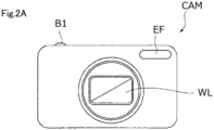
- FIG. 2A and 2B are schematic diagrams illustrating another example in which the optical device according to the present embodiment is used as an imaging device.
- FIG. 2A is a front view illustrating the imaging device CAM
- FIG. 2B is a rear view illustrating the imaging device CAM.
- the imaging device CAM is a so-called digital still camera (non-lens-interchangeable camera), and the photographing lens WL (optical system) includes an optical element based on the optical glass according to the present embodiment.
- a power button (not shown) of the imaging device CAM is pressed, a shutter (not shown) of the photographing lens WL is opened, and the light from a subject (object) is condensed by the photographing lens WL and focused on the imaging element arranged on the image plane.
- the subject image formed on the imaging element is displayed on a liquid crystal monitor M arranged behind the imaging device CAM.
- a photographer determines the arrangement of the subject image while looking at the liquid crystal monitor M, and then presses down a release button B1 to capture the subject image with the imaging element and record and save the image in a memory (not shown).
- the imaging device CAM has an auxiliary light-emitting unit EF that emits auxiliary light when the subject is dark, a function button B2 or the like, used for setting various conditions of the imaging device CAM, or the like.
- an optical system used in such a digital camera is required to have higher resolution, lighter weight, and smaller size.
- it is effective to use glasses having different dispersion characteristics in the optical system.
- the optical glass according to the present embodiment is suitable as a member of such optical instrument.
- the optical instrument applicable to the present embodiment is not limited to the imaging device described above, but may include, for example, a projector or the like.
- the optical element is not limited to a lens, but may include, for example, a prism or the like.
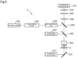
- FIG. 3 is a block diagram illustrating an example of a configuration of a multi-photon microscope 2 using the optical glass according to the present embodiment.
- the multi-photon microscope 2 includes an objective lens 206, a condensing lens 208, and an image forming lens 210. At least one of the objective lens 206, the condensing lens 208, and the image forming lens 210 includes an optical element using the optical glass according to the present embodiment as a mother material.
- description is mainly made on the optical system of the multi-photon microscope 2.
- a pulse laser device 201 emits ultrashort pulse light having, for example, a near infrared wavelength (approximately 1,000 nm) and a pulse width of a femtosecond unit (for example, 100 femtoseconds).
- ultrashort pulse light immediately after being emitted from the pulse laser device 201 is linearly polarized light that is polarized in a predetermined direction.
- a pulse division device 202 divides the ultrashort pulse light, increases a repetition frequency of the ultrashort pulse light, and emits the ultrashort pulse light.
- a beam adjustment unit 203 has a function of adjusting a beam diameter of the ultrashort pulse light, which enters from the pulse division device 202, to a pupil diameter of the objective lens 206, a function of adjusting convergence and divergence angles of the ultrashort pulse light in order to correct chromatic aberration (a focus difference) on an axis of a wavelength of multi-photon excitation light emitted from a sample S and the wavelength of the ultrashort pulse light, a pre-chirp function (group velocity dispersion compensation function) providing inverse group velocity dispersion to the ultrashort pulse light in order to correct the pulse width of the ultrashort pulse light, which is increased due to group velocity dispersion at the time of passing through the optical system, and the like.
- the ultrashort pulse light emitted from the pulse laser device 201 have a repetition frequency increased by the pulse division device 202, and is subjected to the above-mentioned adjustments by the beam adjustment unit 203. Furthermore, the ultrashort pulse light emitted from the beam adjustment unit 203 is reflected on a dichroic mirror 204 in a direction toward a dichroic mirror 205, passes through the dichroic mirror 205, is converged by the objective lens 206, and is radiated to the sample S. At this time, an observation surface of the sample S may be scanned with the ultrashort pulse light through use of scanning means (not illustrated).
- a fluorescent pigment by which the sample S is dyed is subjected to multi-photon excitation in an irradiated region with the ultrashort pulse light and the vicinity thereof on the sample S, and fluorescence having a wavelength shorter than an infrared wavelength of the ultrashort pulse light (hereinafter, also referred to "observation light”) is emitted.
- the observation light emitted from the sample S in a direction toward the objective lens 206 is collimated by the objective lens 206, and is reflected on the dichroic mirror 205 or passes through the dichroic mirror 205 depending on the wavelength.
- the observation light reflected on the dichroic mirror 205 enters a fluorescence detection unit 207.
- the fluorescence detection unit 207 is formed of a barrier filter, a photo multiplier tube (PMT), or the like, receives the observation light reflected on the dichroic mirror 205, and outputs an electronic signal depending on an amount of the light. Further, the fluorescence detection unit 207 detects the observation light over the observation surface of the sample S, in conformity with the ultrashort pulse light scanning on the observation surface of the sample S.
- the observation light passing through the dichroic mirror 205 is de-scanned by scanning means (not illustrated), passes through the dichroic mirror 204, is converged by the condensing lens 208, passes through a pinhole 209 provided at a position substantially conjugate to a focal position of the objective lens 206, passes through the image forming lens 210, and enters a fluorescence detection unit 211.
- the fluorescence detection unit 211 is formed of a barrier filter, a PMT, or the like, receives the observation light forming an image on a light formed by the image forming lens 210 on the reception surface of the fluorescence detection unit 211, and outputs an electronic signal depending on an amount of the light. Further, the fluorescence detection unit 211 detects the observation light over the observation surface of the sample S, in conformity with the ultrashort pulse light scanning on the observation surface of the sample S.
- all the observation light emitted from the sample S in a direction toward the objective lens 206 may be detected by the fluorescence detection unit 211 by excluding the dichroic mirror 205 from the optical path.
- the observation light emitted from the sample S in a direction opposite to the objective lens 206 is reflected on a dichroic mirror 212, and enters a fluorescence detection unit 213.
- the fluorescence detection unit 213 is formed of, for example, a barrier filter, a PMT, or the like, receives the observation light reflected on the dichroic mirror 212, and outputs an electronic signal depending on an amount of the light. Further, the fluorescence detection unit 213 detects the observation light over the observation surface of the sample S, in conformity with the ultrashort pulse light scanning on the observation surface of the sample S.
- the electronic signals output from the fluorescence detection units 207, 211, and 213 are input to, for example, a computer (not illustrated).
- the computer is capable of generating an observation image, displaying the generated observation image, storing data on the observation image, based on the input electronic signals.
- FIG. 4 is a schematic diagram illustrating an exemplary cemented lens according to the present embodiment.
- the cemented lens 3 is a combinational lens having a first lens element 301 and a second lens element 302. At least one of the first lens element and the second lens element is formed using the optical glass according to the present embodiment.
- the first lens element and the second lens element are bonded by interposing a bonding member 303.
- As the bonding member 303 an adhesive or the like known in the art may be used.
- the lens included in the cemented lens may be referred to as a "lens element" as described above from the viewpoint of clarifying that the lens is an element of the cemented lens.
- the cemented lens according to the present embodiment is useful from the viewpoint of chromatic aberration correction, and can be suitably used in the optical element, the optical system, the optical device, or the like as described above.
- an optical system including the cemented lens can be particularly suitably used in an interchangeable lens for camera, an optical device, or the like.
- the present invention may include a cemented lens using three or more lens elements without limiting thereto. In the case of the cemented lens using three or more lens elements, at least one of the three or more lens elements may be formed using the optical glass according to the present embodiment.
- the optical glasses according to each example and each comparative example were produced in the following procedure. First, a glass material selected from oxides, hydroxides, phosphate compounds (such as phosphate or orthophosphoric acid), carbonates, nitrates, or the like was weighed to obtain the compositions (mass%) shown in each table. Then, the weighed raw materials were mixed, put into a platinum crucible, melted at a temperature of 1100 to 1300°C, and homogenized by stirring. After removing bubbles, the temperature was lowered to an appropriate level. Then, the molten materials were cast into a mold, gradually cooled, and molded to obtain each sample.
- a glass material selected from oxides, hydroxides, phosphate compounds (such as phosphate or orthophosphoric acid), carbonates, nitrates, or the like was weighed to obtain the compositions (mass%) shown in each table. Then, the weighed raw materials were mixed, put into a platinum crucible, melted at a temperature of 1100 to
- n d denotes a refractive index of the glass with respect to light having a wavelength of 587.562 nm.
- ⁇ d was obtained from the following Equation (1).
- ⁇ d n d ⁇ 1 / n F ⁇ n C
- the partial dispersion ratio (P g, F ) of each sample indicates a ratio of the partial dispersion (n g -n F ) with respect to the main dispersion (n F -n C ), and was obtained from the following Equation (2).
- n g denotes a refractive index of the glass with respect to light having a wavelength of 435.835 nm.
- the value of the partial dispersion ratio (P g, F ) was set to four decimal places.
- P g , F n g ⁇ n F / n F ⁇ n C
- the specific gravity (S g ) of each sample was determined from the mass ratio with respect to the same volume of pure water at a temperature of 4°C.
- Tables 1 to 11 show the compositions and the evaluation results of the physical properties for the optical glasses of each of the examples and comparative examples on the basis of the mass% of each component with respect to the oxide.
- R Li, Na, or K.
- Comparative Example 2 since the optical glass was not obtainable, the physical property was set to "unmeasurable”.
- the optical glass according to the present example has a low specific gravity while having a high dispersibility.
- coloring is suppressed, and excellent transmittance is obtained in the optical glass according to the present example.
Landscapes
- Chemical & Material Sciences (AREA)
- Life Sciences & Earth Sciences (AREA)
- Engineering & Computer Science (AREA)
- Chemical Kinetics & Catalysis (AREA)
- General Chemical & Material Sciences (AREA)
- Geochemistry & Mineralogy (AREA)
- Materials Engineering (AREA)
- Organic Chemistry (AREA)
- Physics & Mathematics (AREA)
- General Physics & Mathematics (AREA)
- Optics & Photonics (AREA)
- Glass Compositions (AREA)
Applications Claiming Priority (3)
| Application Number | Priority Date | Filing Date | Title |
|---|---|---|---|
| JP2017208104 | 2017-10-27 | ||
| PCT/JP2018/016041 WO2019082419A1 (ja) | 2017-10-27 | 2018-04-18 | 光学ガラス、これを用いた光学素子、接合レンズ、光学系、カメラ用交換レンズ及び光学装置 |
| EP18871384.6A EP3702336B1 (de) | 2017-10-27 | 2018-04-18 | Optisches glas und optisches element, zementierte linse, optisches system, austauschbare linse für kamera und optische vorrichtung damit |
Related Parent Applications (2)
| Application Number | Title | Priority Date | Filing Date |
|---|---|---|---|
| EP18871384.6A Division EP3702336B1 (de) | 2017-10-27 | 2018-04-18 | Optisches glas und optisches element, zementierte linse, optisches system, austauschbare linse für kamera und optische vorrichtung damit |
| EP18871384.6A Division-Into EP3702336B1 (de) | 2017-10-27 | 2018-04-18 | Optisches glas und optisches element, zementierte linse, optisches system, austauschbare linse für kamera und optische vorrichtung damit |
Publications (2)
| Publication Number | Publication Date |
|---|---|
| EP4365643A2 true EP4365643A2 (de) | 2024-05-08 |
| EP4365643A3 EP4365643A3 (de) | 2024-05-22 |
Family
ID=66246355
Family Applications (2)
| Application Number | Title | Priority Date | Filing Date |
|---|---|---|---|
| EP24165287.4A Pending EP4365643A3 (de) | 2017-10-27 | 2018-04-18 | Optisches glas und optisches element, zementierte linse, optisches system, austauschbare linse für kamera und optische vorrichtung damit |
| EP18871384.6A Active EP3702336B1 (de) | 2017-10-27 | 2018-04-18 | Optisches glas und optisches element, zementierte linse, optisches system, austauschbare linse für kamera und optische vorrichtung damit |
Family Applications After (1)
| Application Number | Title | Priority Date | Filing Date |
|---|---|---|---|
| EP18871384.6A Active EP3702336B1 (de) | 2017-10-27 | 2018-04-18 | Optisches glas und optisches element, zementierte linse, optisches system, austauschbare linse für kamera und optische vorrichtung damit |
Country Status (5)
| Country | Link |
|---|---|
| US (2) | US11724959B2 (de) |
| EP (2) | EP4365643A3 (de) |
| JP (2) | JP7140137B2 (de) |
| CN (2) | CN116514393A (de) |
| WO (1) | WO2019082419A1 (de) |
Families Citing this family (9)
| Publication number | Priority date | Publication date | Assignee | Title |
|---|---|---|---|---|
| EP4365643A3 (de) * | 2017-10-27 | 2024-05-22 | Nikon Corporation | Optisches glas und optisches element, zementierte linse, optisches system, austauschbare linse für kamera und optische vorrichtung damit |
| CN113165954A (zh) * | 2018-11-30 | 2021-07-23 | 日本光硝子株式会社 | 光学玻璃、光学元件、光学系统、更换镜头和光学装置 |
| JP7325253B2 (ja) * | 2019-07-12 | 2023-08-14 | 光ガラス株式会社 | 光学ガラス、光学素子、光学系、交換レンズ及び光学装置 |
| JP7401236B2 (ja) * | 2019-09-26 | 2023-12-19 | Hoya株式会社 | 光学ガラスおよび光学素子 |
| WO2022102044A1 (ja) * | 2020-11-12 | 2022-05-19 | 株式会社ニコン | 光学ガラス、光学素子、光学系、接合レンズ、カメラ用交換レンズ、顕微鏡用対物レンズ、及び光学装置 |
| EP4245735A4 (de) * | 2020-11-12 | 2024-07-24 | Nikon Corporation | Optisches glas, optisches element, optisches system, dublettlinse, wechselobjektiv für eine kamera, objektivlinse für mikroskop und optische vorrichtung |
| JP7606351B2 (ja) * | 2021-01-13 | 2024-12-25 | Hoya株式会社 | 光学ガラスおよび光学素子 |
| WO2025135173A1 (ja) * | 2023-12-22 | 2025-06-26 | 株式会社ニコン | 光学ガラス、光学素子、光学系、顕微鏡用対物レンズ、カメラ用交換レンズ、内視鏡装置、及び光学装置 |
| WO2025142288A1 (ja) * | 2023-12-25 | 2025-07-03 | 株式会社ニコン | 光学ガラス、光学素子、光学系、接合レンズ、顕微鏡用対物レンズ、カメラ用交換レンズ、内視鏡装置、及び光学装置 |
Citations (2)
| Publication number | Priority date | Publication date | Assignee | Title |
|---|---|---|---|---|
| JP2006219365A (ja) | 2005-01-17 | 2006-08-24 | Ohara Inc | ガラス |
| JP2017208104A (ja) | 2015-12-01 | 2017-11-24 | マクセルホールディングス株式会社 | 表示装置 |
Family Cites Families (22)
| Publication number | Priority date | Publication date | Assignee | Title |
|---|---|---|---|---|
| US3328181A (en) * | 1963-03-28 | 1967-06-27 | Bausch & Lomb | Metaphosphate glass |
| JPS5378217A (en) * | 1976-12-22 | 1978-07-11 | Hoya Glass Works Ltd | Phosphate optical glass through which light beam length beeing little dependnt on temperature |
| JPS54112915A (en) * | 1978-02-24 | 1979-09-04 | Nippon Chemical Ind | Optical glass |
| FR2504515A1 (fr) * | 1981-04-27 | 1982-10-29 | Essilor Int | Procede pour l'obtention d'un verre mineral a gradient d'indice, et article, en particulier lentille ophtalmique, en un tel verre |
| JP2561835B2 (ja) | 1987-04-23 | 1996-12-11 | 株式会社 オハラ | 光学ガラス |
| JP2634250B2 (ja) * | 1989-08-25 | 1997-07-23 | 日本碍子株式会社 | 模様付け用インク及びこれにより模様付けされた製品 |
| JP3136125B2 (ja) * | 1997-11-11 | 2001-02-19 | 川崎製鉄株式会社 | 琺瑯用フリット |
| JP4478818B2 (ja) * | 1999-07-22 | 2010-06-09 | 奥野製薬工業株式会社 | 低融点ガラス組成物 |
| CN1576252B (zh) * | 2003-06-30 | 2010-04-28 | Hoya株式会社 | 精密加压成形用预成形体、光学元件及各自的制备方法 |
| JP2005053743A (ja) | 2003-08-05 | 2005-03-03 | Minolta Co Ltd | 光学ガラス及び光学素子 |
| CN1903765A (zh) * | 2005-07-28 | 2007-01-31 | Hoya株式会社 | 光学玻璃、光学元件及其制造方法 |
| JP5863227B2 (ja) * | 2009-09-30 | 2016-02-16 | 株式会社オハラ | 光学部品用ガラス部材、光学部品の製造方法及び光学部品用ガラス組成物 |
| JP5364568B2 (ja) * | 2009-12-28 | 2013-12-11 | Hoya株式会社 | プレス成形用ガラス素材、プレス成形用ガラス素材の製造方法、および光学素子の製造方法 |
| CN102367198A (zh) * | 2010-06-23 | 2012-03-07 | 株式会社小原 | 光学玻璃、预成型坯及光学元件 |
| CN103459339A (zh) * | 2011-03-29 | 2013-12-18 | 株式会社小原 | 光学玻璃、预成型坯以及光学元件 |
| TWI618684B (zh) * | 2013-02-19 | 2018-03-21 | Hoya Corp | Optical glass, optical glass blank, glass material for press molding, optical element, and manufacturing method thereof |
| CN103241942B (zh) * | 2013-05-24 | 2016-01-13 | 成都尤利特光电科技有限公司 | 高折射低色散光学玻璃及其制造方法 |
| US10071931B2 (en) | 2013-12-18 | 2018-09-11 | Hoya Corporation | Optical glass and optical element |
| JP6603449B2 (ja) * | 2014-09-30 | 2019-11-06 | Hoya株式会社 | ガラス、プレス成形用ガラス素材、光学素子ブランク、および光学素子 |
| CN105481244A (zh) * | 2014-10-07 | 2016-04-13 | 株式会社小原 | 光学玻璃、透镜预成型体及光学元件 |
| EP4365643A3 (de) * | 2017-10-27 | 2024-05-22 | Nikon Corporation | Optisches glas und optisches element, zementierte linse, optisches system, austauschbare linse für kamera und optische vorrichtung damit |
| WO2020117651A1 (en) * | 2018-12-07 | 2020-06-11 | Corning Incorporated | High-refractive index phosphate glass |
-
2018
- 2018-04-18 EP EP24165287.4A patent/EP4365643A3/de active Pending
- 2018-04-18 JP JP2019549822A patent/JP7140137B2/ja active Active
- 2018-04-18 WO PCT/JP2018/016041 patent/WO2019082419A1/ja not_active Ceased
- 2018-04-18 EP EP18871384.6A patent/EP3702336B1/de active Active
- 2018-04-18 CN CN202310518186.9A patent/CN116514393A/zh active Pending
- 2018-04-18 CN CN201880067237.8A patent/CN111225885A/zh active Pending
-
2020
- 2020-04-27 US US16/859,365 patent/US11724959B2/en active Active
-
2022
- 2022-09-07 JP JP2022142347A patent/JP7388505B2/ja active Active
-
2023
- 2023-06-23 US US18/213,534 patent/US12234183B2/en active Active
Patent Citations (2)
| Publication number | Priority date | Publication date | Assignee | Title |
|---|---|---|---|---|
| JP2006219365A (ja) | 2005-01-17 | 2006-08-24 | Ohara Inc | ガラス |
| JP2017208104A (ja) | 2015-12-01 | 2017-11-24 | マクセルホールディングス株式会社 | 表示装置 |
Also Published As
| Publication number | Publication date |
|---|---|
| US12234183B2 (en) | 2025-02-25 |
| JP7140137B2 (ja) | 2022-09-21 |
| CN116514393A (zh) | 2023-08-01 |
| JP2022184891A (ja) | 2022-12-13 |
| EP3702336A4 (de) | 2021-08-18 |
| EP3702336A1 (de) | 2020-09-02 |
| US11724959B2 (en) | 2023-08-15 |
| US20200255326A1 (en) | 2020-08-13 |
| WO2019082419A1 (ja) | 2019-05-02 |
| CN111225885A (zh) | 2020-06-02 |
| US20230348316A1 (en) | 2023-11-02 |
| EP4365643A3 (de) | 2024-05-22 |
| JPWO2019082419A1 (ja) | 2020-11-19 |
| EP3702336B1 (de) | 2024-05-01 |
| JP7388505B2 (ja) | 2023-11-29 |
Similar Documents
| Publication | Publication Date | Title |
|---|---|---|
| US12234183B2 (en) | Optical glass, and optical element, cemented lens, optical system, interchangeable lens for camera and optical device using same | |
| US20200115271A1 (en) | Optical glass, and optical element, optical system, cemented lens, interchangeable camera lens, and optical device using same | |
| US20210403371A1 (en) | Optical glass, optical element, optical system, interchangeable lens, and optical device | |
| JP7783316B2 (ja) | 光学ガラス、光学素子、光学系、交換レンズ及び光学装置 | |
| US20230331623A1 (en) | Optical glass, optical element, optical system, cemented lens, interchangeable lens for camera, objective lens for microscope, and optical device | |
| US20230278914A1 (en) | Optical glass, optical element, optical system, cemented lens, interchangeable lens for camera, objective lens for microscope, and optical device | |
| JP2021054693A (ja) | 光学ガラス、光学ガラスを用いた光学素子、光学系、交換レンズ、光学装置、及び光学ガラスの製造方法 | |
| EP4011844B1 (de) | Optisches glas, optisches element, optisches system, austauschbare linse und optische vorrichtung | |
| EP3385233B1 (de) | Optisches glas, optisches element mit dem optischen glas und optische vorrichtung | |
| US20240101465A1 (en) | Optical glass, optical element, optical system, cemented lens, interchangeable camera lens, microscope objective lens, and optical device | |
| EP4501874A1 (de) | Optisches glas, optisches element, wechselobjektiv für eine kamera, objektiv, sinterobjektiv, optisches system, spiegelelement und positionsmesseinrichtung | |
| JP7325253B2 (ja) | 光学ガラス、光学素子、光学系、交換レンズ及び光学装置 | |
| CN121843905A (zh) | 光学玻璃、光学元件、光学系统、显微镜用物镜、照相机用更换镜头、接合透镜及光学装置 |
Legal Events
| Date | Code | Title | Description |
|---|---|---|---|
| PUAI | Public reference made under article 153(3) epc to a published international application that has entered the european phase |
Free format text: ORIGINAL CODE: 0009012 |
|
| STAA | Information on the status of an ep patent application or granted ep patent |
Free format text: STATUS: REQUEST FOR EXAMINATION WAS MADE |
|
| REG | Reference to a national code |
Ref country code: DE Ref legal event code: R079 Free format text: PREVIOUS MAIN CLASS: G02B0001000000 Ipc: C03C0003210000 |
|
| PUAL | Search report despatched |
Free format text: ORIGINAL CODE: 0009013 |
|
| 17P | Request for examination filed |
Effective date: 20240321 |
|
| AC | Divisional application: reference to earlier application |
Ref document number: 3702336 Country of ref document: EP Kind code of ref document: P |
|
| AK | Designated contracting states |
Kind code of ref document: A2 Designated state(s): AL AT BE BG CH CY CZ DE DK EE ES FI FR GB GR HR HU IE IS IT LI LT LU LV MC MK MT NL NO PL PT RO RS SE SI SK SM TR |
|
| AK | Designated contracting states |
Kind code of ref document: A3 Designated state(s): AL AT BE BG CH CY CZ DE DK EE ES FI FR GB GR HR HU IE IS IT LI LT LU LV MC MK MT NL NO PL PT RO RS SE SI SK SM TR |
|
| RIC1 | Information provided on ipc code assigned before grant |
Ipc: G02B 1/00 20060101ALI20240415BHEP Ipc: C03C 3/066 20060101ALI20240415BHEP Ipc: C03C 3/064 20060101ALI20240415BHEP Ipc: C03C 3/062 20060101ALI20240415BHEP Ipc: C03C 3/21 20060101AFI20240415BHEP |
|
| RBV | Designated contracting states (corrected) |
Designated state(s): AL AT BE BG CH CY CZ DE DK EE ES FI FR GB GR HR HU IE IS IT LI LT LU LV MC MK MT NL NO PL PT RO RS SE SI SK SM TR |