EP4367347B1 - Verfahren zum automatischen einstellen einer veränderbaren maststellung eines verstellbaren verteilermasts einer bau- und/oder dickstoffpumpenvorrichtung und system - Google Patents
Verfahren zum automatischen einstellen einer veränderbaren maststellung eines verstellbaren verteilermasts einer bau- und/oder dickstoffpumpenvorrichtung und system Download PDFInfo
- Publication number
- EP4367347B1 EP4367347B1 EP22738466.6A EP22738466A EP4367347B1 EP 4367347 B1 EP4367347 B1 EP 4367347B1 EP 22738466 A EP22738466 A EP 22738466A EP 4367347 B1 EP4367347 B1 EP 4367347B1
- Authority
- EP
- European Patent Office
- Prior art keywords
- boom
- actual
- determining
- mast
- variable
- Prior art date
- Legal status (The legal status is an assumption and is not a legal conclusion. Google has not performed a legal analysis and makes no representation as to the accuracy of the status listed.)
- Active
Links
Images


Classifications
-
- E—FIXED CONSTRUCTIONS
- E04—BUILDING
- E04G—SCAFFOLDING; FORMS; SHUTTERING; BUILDING IMPLEMENTS OR AIDS, OR THEIR USE; HANDLING BUILDING MATERIALS ON THE SITE; REPAIRING, BREAKING-UP OR OTHER WORK ON EXISTING BUILDINGS
- E04G21/00—Preparing, conveying, or working-up building materials or building elements in situ; Other devices or measures for constructional work
- E04G21/02—Conveying or working-up concrete or similar masses able to be heaped or cast
- E04G21/04—Devices for both conveying and distributing
- E04G21/0418—Devices for both conveying and distributing with distribution hose
- E04G21/0445—Devices for both conveying and distributing with distribution hose with booms
- E04G21/0463—Devices for both conveying and distributing with distribution hose with booms with boom control mechanisms, e.g. to automate concrete distribution
-
- B—PERFORMING OPERATIONS; TRANSPORTING
- B66—HOISTING; LIFTING; HAULING
- B66C—CRANES; LOAD-ENGAGING ELEMENTS OR DEVICES FOR CRANES, CAPSTANS, WINCHES, OR TACKLES
- B66C23/00—Cranes comprising essentially a beam, boom, or triangular structure acting as a cantilever and mounted for translatory of swinging movements in vertical or horizontal planes or a combination of such movements, e.g. jib-cranes, derricks, tower cranes
- B66C23/62—Constructional features or details
- B66C23/64—Jibs
- B66C23/68—Jibs foldable or otherwise adjustable in configuration
-
- B—PERFORMING OPERATIONS; TRANSPORTING
- B66—HOISTING; LIFTING; HAULING
- B66C—CRANES; LOAD-ENGAGING ELEMENTS OR DEVICES FOR CRANES, CAPSTANS, WINCHES, OR TACKLES
- B66C23/00—Cranes comprising essentially a beam, boom, or triangular structure acting as a cantilever and mounted for translatory of swinging movements in vertical or horizontal planes or a combination of such movements, e.g. jib-cranes, derricks, tower cranes
- B66C23/88—Safety gear
-
- E—FIXED CONSTRUCTIONS
- E04—BUILDING
- E04G—SCAFFOLDING; FORMS; SHUTTERING; BUILDING IMPLEMENTS OR AIDS, OR THEIR USE; HANDLING BUILDING MATERIALS ON THE SITE; REPAIRING, BREAKING-UP OR OTHER WORK ON EXISTING BUILDINGS
- E04G21/00—Preparing, conveying, or working-up building materials or building elements in situ; Other devices or measures for constructional work
- E04G21/02—Conveying or working-up concrete or similar masses able to be heaped or cast
- E04G21/04—Devices for both conveying and distributing
- E04G21/0418—Devices for both conveying and distributing with distribution hose
- E04G21/0436—Devices for both conveying and distributing with distribution hose on a mobile support, e.g. truck
Definitions
- the invention relates to a method for automatically adjusting a variable mast position of an adjustable distribution boom of a construction and/or thick matter pumping device and a system.
- the EP 2 813 643 A1 discloses a stability control system for pump trucks comprising a detection device and a control device, wherein the detection device is used to detect current pumping state parameters, boom posture parameters, landing posture parameters, pump truck body position state parameters, and current numerical signals of external load parameters acting on a boom system of the pump truck, and wherein the control device is used to receive the current numerical signals of the above parameters, calculate the overall machine center of gravity position of the concrete pump truck according to the parameters, and perform stability control for the pump truck according to the overall machine center of gravity position within a pump truck stability range.
- the stability control system comprehensively considers the pump truck's inherent factors and the influencing factors of external load, the calculation accuracy of the center of gravity is high, and the construction safety of the concrete pump truck is improved.
- the EP 2 813 643 A1 a method for stability control of a pump truck and a pump truck including the stability control system of the pump truck.
- the WO 2018/115270 A1 reveals a mobile large manipulator.
- the invention is based on the object of providing a method for automatically adjusting a variable mast position of an adjustable distribution boom of a construction and/or thick matter pumping device and a system, in particular which has improved properties in each case.
- the invention solves this problem by providing a method having the features of claim 1 and a system having the features of claim 7.
- Advantageous developments and/or embodiments of the invention are described in the dependent claims.
- the inventive, in particular automatic, method is designed, configured, or provided for automatically adjusting a variable mast position of a, in particular flexibly adjustable, distribution boom of a construction and/or slurry pumping device. At least one identical tip position of a mast tip of the distribution boom can be achieved through different mast positions or mast poses, in particular of the distribution boom.
- the method comprises or has the step of: determining, in particular automatically determining, and adjusting, in particular automatically adjusting, a mast position, in particular at least one value of the mast position, in particular of the distribution boom, depending on a predetermined variable or a parameter, in particular a value of the variable, determining a tip position, in particular a value of the tip position, in particular of the mast tip, and based on, in particular at least one optimization criterion.
- the optimization criterion is a minimized or reduced, particularly mechanical, tipping or load moment, in particular a minimized value of the tipping moment, of the placing boom in relation to a support system, in particular the placing boom, the construction and/or slurry pumping device.
- the tipping moment depends on the boom position.
- the distribution boom can be a construction and/or thick material distribution boom.
- the construction and/or thick matter pump device can be mobile, in particular mobile, in particular a car construction and/or thick matter pump.
- the construction and/or thick matter pump device can be designed to pump construction and/or thick matter.
- Building material can refer to mortar, cement, screed, concrete, and/or plaster. Additionally or alternatively, thick matter can refer to sludge.
- At least the same top position of the mast tip can be achieved by at least three, in particular at least ten, different mast positions.
- the mast tip can be a free end of the distribution boom.
- the variable determining the tip position can be a target variable and/or determining a target tip position, in particular of the mast tip. Additionally or alternatively, the variable can be a direction, in particular a target direction, and/or a speed, in particular a target speed, of a movement, in particular a target movement, of the mast tip. Further additionally or alternatively, the variable can be a travel command or travel command, in particular to reach the tip position. Further additionally or alternatively, the variable can be specified by an operator or user, in particular of the distribution boom and/or the construction and/or thick matter pump device. Further additionally or alternatively, the method can comprise the step of determining, in particular detecting, a specification of the variable, in particular by the operator.
- optimization criterion can be maintaining a distance from at least one obstacle, such as a remainder of the construction and/or thick matter pumping device and/or another distribution boom, by the distribution boom.
- the tipping moment of the placing boom can be relative to or at a base of the placing boom, particularly a four-point bearing. Additionally or alternatively, the tipping moment can be caused by the boom position.
- the step comprises: determining, in particular automatically determining and/or searching and/or calculating, and setting, in particular automatically setting, a Change, in particular of the mast position, in particular directly or without detours, starting from, in particular at, a, in particular instantaneous or current, actual mast position, in particular of the placing boom, in particular at least, based on, in particular to, a, in particular greatest, minimization, in particular of the tipping moment, in particular directly or without detours, starting from, in particular at, a, in particular instantaneous or current, actual tipping moment of the placing boom in relation to the support system.
- the actual tipping moment depends on the actual mast position.
- determining and setting a mast position to a, in particular nearest, locally minimized or minimum tipping moment This enables a local and/or, in particular thus, simple and/or rapid minimization of the tipping moment, in particular and thereby achieving and/or maintaining the peak position, in particular the target peak position.
- the tipping moment minimized in this way does not need to be or can be a globally minimized or minimum tipping moment.
- the phrase "a, in particular steepest, descent" can be used synonymously with the phrase "a, in particular greatest, minimization.”
- the method can be referred to as a gradient-based method.
- the method can comprise the step of determining, in particular recording, the actual mast position.
- the step comprises: controlling, in particular automatically controlling and/or regulating, the boom position to, in particular, reach and/or maintain the peak position, in particular the target peak position, in particular starting from the, in particular instantaneous or current, actual peak position of the distribution boom and/or during the determination and adjustment of the change and/or as long as the actual tipping moment is minimized, if provided.
- the method can comprise the step of: determining, in particular detecting, the actual peak position.
- the step comprises: determining and adjusting the change and controlling, in particular regulating, the mast position by determining, in particular automatically determining and/or searching and/or calculating, a solution, in particular a value of the solution, for a kinematic relationship, in particular at least the minimization of the actual tipping moment and the achievement and/or maintenance of the peak position.
- a solution in particular a value of the solution
- the kinematic relationship can Describe, in particular model, minimization of the tipping moment and the achievement and/or maintenance of the peak position.
- achieving and/or maintaining the peak position can take priority over, in particular further, minimization of the tipping moment.
- the mast tip can reach and/or maintain the peak position and the tipping moment does or cannot reach a, in particular the next, local minimum, in particular completely.
- the kinematic relationship can take into account, in particular have, adjustment ranges.
- the distribution boom comprises or has a plurality of, in particular flexibly, adjustable mast joints.
- the mast position can be changed by a changeable joint position combination or configuration of the mast joints.
- at least the same peak position can be achieved by different joint position combinations, in particular of the mast joints.
- the mast joints have or have different, in particular the different, adjustment ranges, in particular different values of the adjustment ranges.
- the step comprises: determining, in particular automatically determining, and setting, in particular automatically setting, a joint position combination, in particular at least one value of the joint position combination, in particular of the mast joints, depending on the predetermined variable and based on, in particular at least, the optimization criterion, in particular and taking into account the adjustment ranges.
- the tipping moment depends on the joint position combination.
- at least one of the mast joints can have, in particular be, an articulated, rotary and/or sliding joint.
- at least one of the adjustment ranges can have, in particular be, an angular range.
- at least one of the adjustment ranges can be defined, in particular limited, by at least one, in particular mechanical, stop of at least one of the mast joints.
- the construction and/or thick matter pump device, in particular the distribution boom can have several articulated drives for adjusting the mast joints or for changing or setting the joint position combination.
- one of the mast joints can be at a non-free or fixed end or the mast base of the distribution boom.
- the distribution boom is rollable and/or Z-foldable by means of the boom joints, in particular roll-Z-foldable.
- the distribution boom comprises or has a plurality of boom segments or sections that are adjustable, in particular relative to one another and/or flexibly.
- the mast position can be changed by a variable adjustment combination or configuration of the mast segments, in particular relative to one another.
- at least the same tip position can be achieved by different adjustment combinations, in particular of the mast segments relative to one another.
- the mast segments have or have different masses, in particular different mass values, and/or different lengths, in particular different length values, and/or different center of gravity positions or centers of gravity, in particular values of the center of gravity positions.
- the step comprises: determining, in particular automatically determining, and setting, in particular automatically setting, an adjustment combination, in particular at least one value of the adjustment combination, depending on the predetermined variable and based on, in particular at least, the optimization criterion, in particular and taking into account the masses and/or the lengths and/or the center of gravity positions.
- the tipping moment depends on the adjustment combination.
- the mast segments can be adjustable by means of the mast joints.
- the construction and/or thick matter pumping device, in particular the distribution boom can have several segment drives for adjusting the boom segments or for changing or adjusting the adjustment combination.
- the support system is adjustable, in particular flexibly.
- the method comprises or has the step of: locking, in particular automatically locking, mast positions, in particular values of the mast positions, and/or tipping moments, in particular values of the tipping moments, depending on a determined variable or a determined parameter, in particular a determined value of the variable, determining at least one variable support configuration or position, in particular at least one variable value of the support configuration and/or an actual support configuration, of the adjustable support system for counteracting the tipping moment, in particular the actual tipping moment.
- This in particular the adjustable support system, enables adaptation to a, in particular local, construction site condition, in particular to a small support area.
- this enables, in particular by locking the boom positions and/or the tipping moments depending on the determined value determining at least the variable support configuration, to minimize, reduce, or lower the risk of the construction and/or slurry pumping device tipping over and/or toppling over and/or, in particular, to increase safety when working with or operating the construction and/or slurry pumping device, in particular when adjusting the placing boom. Furthermore, this enables, in particular by minimizing the tipping moment, to maximize the available working space, in particular of the placing boom.
- the support system can have support booms, in particular support legs, adjustable in a support width and/or flexibly.
- the method can comprise the step of determining, in particular detecting, the support configuration, in particular the actual support configuration.
- the distribution boom comprises or has a conveyor line, in particular a flexibly adjustable one, for conveying construction and/or high-density material.
- the conveyor line can comprise, in particular be, a pipeline.
- the system according to the invention comprises or has an adjustment device.
- the adjustment device is designed or configured for, in particular, the automatic adjustment of a, in particular the, variable mast position of a, in particular the, adjustable placing boom of a, in particular the, construction and/or slurry pumping device. At least one identical, in particular the same, tip position of a, in particular the, mast tip of the placing boom can be achieved through different, in particular the different, mast positions.
- the adjustment device is designed or configured for, in particular, the determination and adjustment of a, in particular the, mast position as a function of a, in particular the, predetermined variable, determining a, in particular the, tip position and based on an, in particular the, optimization criterion.
- the optimization criterion is a minimized, in particular the minimized, tipping moment of the placing boom with respect to a, in particular the, support system of the construction and/or slurry pumping device.
- the tipping moment depends on the mast position.
- the adjustment device is designed or configured for, in particular, determining and adjusting a, in particular the, change starting from a, in particular the, actual boom position based on a, in particular the and/or greatest, minimization starting from a, in particular the, actual tipping moment of the distribution boom with respect to the support system.
- the actual tipping moment depends on the actual boom position.
- the adjustment device is designed or configured for, in particular, controlling, in particular regulating, the boom position to, in particular, reach and/or maintain the peak position, in particular starting from the actual peak position of the distribution boom and/or during the determination and adjustment of the change and/or as long as the actual tipping moment is minimized.
- the adjustment device is designed or configured for, in particular, determining and adjusting the change and designed or configured to, in particular, control, in particular regulate, the mast position by determining a, in particular the, solution for a, in particular the, kinematic relationship between minimizing the actual tipping moment and reaching and/or maintaining the tip position.
- the system in particular the adjustment device, can be designed or configured to, in particular automatically, execute a, in particular the, previously mentioned method.
- the system can comprise the distribution boom, in particular the construction and/or thick matter pump device.
- the adjustment device can be electrical, hydraulic and/or pneumatic.
- the adjustment device can comprise a computing unit, in particular a processor, and/or a memory unit.
- Fig. 1 , 2 , and 3 to 10 show a system 1 according to the invention, in particular comprising an adjustment device 2, and a method according to the invention for automatically adjusting a variable mast position MS of an adjustable distribution boom 3 of a construction and/or thick matter pump device 4. At least one same tip position SPO of a mast tip 3S of the distribution boom 3 can be reached by different mast positions MS, MS'.
- the system 1, in particular the adjustment device 2 is designed, in particular determines and adjusts, a mast position MS as a function of a predetermined variable VG determining a peak position SPO and based on an optimization criterion OK.
- the method comprises the step of determining and adjusting the mast position MS as a function of the specified variable VG, determining the peak position SPO and based on the optimization criterion OK, in particular by means of the system 1, in particular the adjustment device 2.
- the optimization criterion OK is a minimized tipping moment KM of the placing boom 3 with respect to a support system 7 of the construction and/or thick matter pump device 4, in particular a boom base 3F of the placing boom 3.
- the tipping moment KM depends on the boom position MS.
- the system 1 comprises the distribution boom 3, in particular the construction and/or thick matter pump device 4.
- the distribution boom 3 has several adjustable boom joints 5a, 5b, 5c, 5d, 5e.
- the boom position MS can be changed by a variable joint position combination GSK of the boom joints 5a-e.
- the same peak position SPO can be achieved by different joint position combinations GSK, GSK'.
- the boom joints 5a, 5b, 5c, 5d, 5e have different adjustment ranges 5Va, 5Vb, 5Vc, 5Vd, 5Ve.
- This step comprises: determining and setting a joint position combination GSK depending on the specified variable VG and based on the optimization criterion OK, in particular and taking into account the adjustment ranges 5Va-e, in particular by means of the system 1, in particular the adjustment device 2.
- the tipping moment KM depends on the joint position combination GSK.
- the distribution boom 3 is rollable and/or Z-foldable, in particular roll-Z-foldable, by means of the boom joints 5a-e.
- the distribution boom 3 has several, in particular mutually adjustable, boom segments 6a, 6b, 6c, 6d, 6e.
- the boom position MS is adjustable by a variable Adjustment combination VSK of the mast segments 6a-e, in particular relative to one another, is variable.
- the same peak position SPO can be achieved by different adjustment combinations VSK, VSK'.
- the mast segments 6a, 6b, 6c, 6d, 6e have different masses ma, mb, mc, md, me and/or different lengths La, Lb, Lc, Ld, Le and/or different center of gravity positions GPa, GPb, GPc, GPd, GPe.
- the step comprises: determining and setting an adjustment combination VSK depending on the specified variable VG and based on the optimization criterion OK, in particular and taking into account the masses ma-e and/or the lengths La-e and/or the center of gravity positions GPa-e, in particular by means of the system 1, in particular the adjustment device 2.
- the tipping moment KM depends on the adjustment combination VSK.
- the distribution boom 3 has five adjustable boom joints 5a-e. In alternative embodiments, the distribution boom can have at least three boom joints.
- the distribution boom 3 has five boom segments 6a-e. In alternative embodiments, the distribution boom can have at least three boom segments.
- One mast joint and/or one mast segment enables/allows movement of the mast tip.
- Two mast joints and/or two mast segments enable free movement of the mast tip, in particular with height and radius being independent of each other, particularly within certain limits.
- At least three mast joints and/or at least three mast segments enable free movement of the mast tip and adjustment of the mast position via at least one degree of freedom.
- a radius or a distance r and/or a direction or an angle RI of the distribution boom 3, in particular its boom tip 3S, in particular with respect to its boom base 3F and/or the support system 7, can be changed by the changeable joint position combination GSK and/or the changeable adjustment combination VSK.
- the step includes: Determining and setting a change VMS starting from an actual mast position IMS based on a, in particular largest, minimization based on an actual tipping moment IKM of the distribution boom 3 in relation to the support system 7, in particular by means of the system 1, in particular the adjustment device 2.
- the actual tipping moment IKM depends on the actual boom position IMS.
- the greatest minimization of the tipping moment KM means, for example, deriving the function of the tipping moment KM after the change VMS of the mast position MS, in particular the adjustment coordinate or the angle of the mast joints 5a-e, in particular starting from the actual mast position IMS:
- the step further comprises: controlling, in particular regulating, the mast position MS to achieve and/or maintain the peak position SPO, in particular a target peak position SSPO, in particular starting from an actual peak position ISPO of the distribution boom 3 and/or during the determination and adjustment of the change VMS and/or as long as the actual tipping moment IKM is minimized, in particular by means of the system 1, in particular the adjustment device 2.
- v ⁇ SPO ⁇ r ⁇ SPO ⁇ ⁇ ⁇ G ⁇ ⁇ ⁇
- the step comprises: determining and adjusting the change VMS and controlling, in particular regulating, the mast position MS by determining a solution LS for a kinematic relationship KIZ between minimizing the actual tipping moment IKM and achieving and/or maintaining the peak position SPO, in particular by means of the system 1, in particular the adjustment device 2.
- KIZ represents an overdetermined system of equations that, in general, cannot be solved exactly. Instead, the best solution LS of this system of equations can be determined using the least squares method. To do this, the sum of the squares of the errors in the above equation can be minimized.
- the individual components of the method or process minimization of the tipping moment KM, achievement and/or maintenance of the target tip position SSPO, and implementation of the required speeds of the mast joints 5a-e
- these can be considered with different weightings in the cost functional K.
- the diagonal matrix W can have these weights, in particular contain them.
- ⁇ ⁇ opt ⁇ KM ⁇ ⁇ ⁇ G ⁇ r ⁇ SPO ⁇ ⁇ ⁇ G E N T ⁇ W ⁇ ⁇ KM ⁇ ⁇ ⁇ G ⁇ r ⁇ SPO ⁇ ⁇ ⁇ G E N ⁇ 1 ⁇ ⁇ KM ⁇ ⁇ ⁇ G ⁇ r ⁇ SPO ⁇ ⁇ ⁇ G E N T ⁇ W ⁇ C v ⁇ SPO ⁇ ⁇ gef
- the support system 7 is adjustable.
- the method comprises the step of locking mast positions MS" and/or tipping moments KM" as a function of a determined variable EG, determining at least one variable support configuration ASK of the adjustable support system 7 to counteract the tipping moment KM, in particular by means of the system 1, in particular the adjustment device 2.
- the distribution boom 3 has a conveying line 8 for conveying building and/or thick material BDS, in particular conveys.
- the distribution boom 3 has an end hose, in particular a freely hanging one.
- the end hose can be taken into account in the mass me and/or the center of gravity position GPe of the mast segment 6e, in particular the last one.
- the invention provides an advantageous method for automatically adjusting a variable boom position of an adjustable distribution boom of a construction and/or thick matter pumping device and an advantageous system, in particular which has improved properties in each case.
- the method and/or system for automatically minimizing the tipping moment enables the operator or user to maximize the utilization of the working area while releasing the working area based on the actual tipping moment.
- the placing boom can be adjusted at the simple push of a button to minimize the actual tipping moment, thereby releasing additional parts of the working area. This allows the operator or user, without requiring any knowledge of the relationship between tipping moment and boom position, to operate the construction and/or slurry pumping device within the maximum possible range with a minimum support width.
Landscapes
- Engineering & Computer Science (AREA)
- Architecture (AREA)
- Mechanical Engineering (AREA)
- Civil Engineering (AREA)
- Structural Engineering (AREA)
- On-Site Construction Work That Accompanies The Preparation And Application Of Concrete (AREA)
- Jib Cranes (AREA)
Description
- Die Erfindung bezieht sich auf ein Verfahren zum automatischen Einstellen einer veränderbaren Maststellung eines verstellbaren Verteilermasts einer Bau- und/oder Dickstoffpumpenvorrichtung und ein System.
- Die
EP 2 813 643 A1 offenbart ein Stabilitätskontrollsystem für Pumpwagen, das eine Erfassungsvorrichtung und eine Kontrollvorrichtung umfasst, wobei die Erfassungsvorrichtung zum Erfassen aktueller Pumpzustandsparameter, Auslegerhaltungsparameter, Landebeinhaltungsparameter, Pumpwagen-Karosseriepositionszustandsparameter und aktueller numerischer Signale von externen Lastparametern, die auf ein Auslegersystem des Pumpwagens einwirken, verwendet wird, und wobei die Kontrollvorrichtung zum Empfangen der aktuellen numerischen Signale der obigen Parameter, zum Berechnen der Gesamtmaschinenschwerpunktposition des Betonpumpenwagens entsprechend den Parametern und zum Durchführen einer Stabilitätskontrolle für den Pumpwagen entsprechend der Position des Gesamtmaschinenschwerpunkts in einem Pumpwagen-Stabilitätsbereich verwendet wird. Das Stabilitätskontrollsystem berücksichtigt umfassend die Eigenfaktoren des Pumpwagens und die Einflussfaktoren externer Last, die Berechnungsgenauigkeit des Schwerpunkts ist hoch und die Bausicherheit des Betonpumpenwagens wird verbessert. Darüber hinaus offenbart dieEP 2 813 643 A1 ein Verfahren zur Stabilitätskontrolle eines Pumpwagens und einen Pumpwagen, der das Stabilitätskontrollsystem des Pumpwagens umfasst. - Die
WO 2018/115270 A1 offenbart einen fahrbaren Großmanipulator. - Der Erfindung liegt als Aufgabe die Bereitstellung eines Verfahrens zum automatischen Einstellen einer veränderbaren Maststellung eines verstellbaren Verteilermasts einer Bau- und/oder Dickstoffpumpenvorrichtung und eines Systems zugrunde, insbesondere das jeweils verbesserte Eigenschaften aufweist.
- Die Erfindung löst diese Aufgabe durch die Bereitstellung eines Verfahrens mit den Merkmalen des Anspruchs 1 und eines Systems mit den Merkmalen des Anspruchs 7. Vorteilhafte Weiterbildungen und/oder Ausgestaltungen der Erfindung sind in den abhängigen Ansprüchen beschrieben.
- Das erfindungsgemäße, insbesondere automatische, Verfahren ist zum automatischen Einstellen einer veränderbaren Maststellung eines, insbesondere flexibel, verstellbaren Verteilermasts einer Bau- und/oder Dickstoffpumpenvorrichtung ausgebildet bzw. konfiguriert bzw. vorgesehen. Mindestens eine selbe Spitzenposition einer Mastspitze des Verteilermasts ist durch verschiedene Maststellungen bzw. Mastposen, insbesondere des Verteilermasts, erreichbar. Das Verfahren umfasst bzw. weist den Schritt auf: Ermitteln, insbesondere automatisches Ermitteln, und Einstellen, insbesondere automatisches Einstellen, einer Maststellung, insbesondere mindestens eines Werts der Maststellung, insbesondere des Verteilermasts, in Abhängigkeit einer vorgegebenen Größe bzw. eines Parameters, insbesondere eines Werts der Größe, bestimmend eine Spitzenposition, insbesondere einen Wert der Spitzenposition, insbesondere der Mastspitze, und anhand, insbesondere mindestens, eines Optimierungskriteriums. Das Optimierungskriterium ist ein minimiertes bzw. reduziertes, insbesondere mechanisches, Kipp- bzw. Lastmoment, insbesondere ein minimierter Wert des Kippmoments, des Verteilermasts in Bezug auf ein Abstützungssystem, insbesondere des Verteilermasts, der Bau- und/oder Dickstoffpumpenvorrichtung. Das Kippmoment hängt von der Maststellung ab.
- Dies ermöglicht ein Risiko eines Umkippens bzw. Umstürzens der Bau- und/oder Dickstoffpumpenvorrichtung zu minimieren bzw. zu reduzieren bzw. zu erniedrigen und/oder, insbesondere somit, eine Sicherheit beim Arbeiten mit bzw. Betrieb der Bau- und/oder Dickstoffpumpenvorrichtung, insbesondere beim Verstellen des Verteilermasts, zu erhöhen. Zusätzlich oder alternativ ermöglicht dies einen maximierten verfügbaren Arbeitsraum, insbesondere des Verteilermasts, insbesondere wobei der Arbeitsraum von der Maststellung abhängen kann.
- Insbesondere kann der Begriff "selbstständig" synonym für den Begriff "automatisch" verwendet werden.
- Der Verteilermast kann ein Bau- und/oder Dickstoffverteilermast sein.
- Die Bau- und/oder Dickstoffpumpenvorrichtung kann mobil, insbesondere fahrbar, insbesondere eine Auto-Bau- und/oder Dickstoffpumpe, sein.
- Die Bau- und/oder Dickstoffpumpenvorrichtung kann zur Förderung von Bau- und/oder Dickstoff ausgebildet sein.
- Baustoff kann Mörtel, Zement, Estrich, Beton und/oder Putz bezeichnen. Zusätzlich oder alternativ kann Dickstoff Schlamm bezeichnen.
- Mindestens dieselbe Spitzenposition der Mastspitze kann durch mindestens drei, insbesondere mindestens zehn, verschiedene Maststellungen erreichbar sein.
- Mehrere, insbesondere mindestens drei, insbesondere mindestens zehn, Spitzenpositionen der Mastspitze können, insbesondere zu verschiedenen Zeitpunkten, durch, insbesondere jeweils, verschiedene Maststellungen des Verteilermasts erreichbar sein.
- Die Mastspitze kann ein freies Ende des Verteilermasts sein.
- Die Größe bestimmend die Spitzenposition kann eine Soll-Größe und/oder bestimmend eine Soll-Spitzenposition, insbesondere der Mastspitze, sein. Zusätzlich oder alternativ kann die Größe eine Richtung, insbesondere eine Soll-Richtung, und/oder eine Geschwindigkeit, insbesondere eine Soll-Geschwindigkeit, einer Bewegung, insbesondere einer Soll-Bewegung, der Mastspitze sein. Weiter zusätzlich oder alternativ kann die Größe ein Fahrbefehl bzw. Fahrkommando, insbesondere zu einer Erreichung der Spitzenposition, sein. Weiter zusätzlich oder alternativ kann die Größe durch einen Bediener bzw. Benutzer, insbesondere des Verteilermasts und/oder der Bau- und/oder Dickstoffpumpenvorrichtung, vorgegeben sein. Weiter zusätzlich oder alternativ kann das Verfahren den Schritt aufweisen: Ermitteln, insbesondere Erfassen, einer Vorgabe der Größe, insbesondere durch den Bediener.
- Ein, insbesondere weiteres, Optimierungskriterium kann ein Halten eines Abstands zu mindestens einem Hindernis, wie z.B. einem Rest der Bau- und/oder Dickstoffpumpenvorrichtung und/oder einem weiteren Verteilermast, durch den Verteilermast sein.
- Das Kippmoment des Verteilermasts kann in Bezug auf einen bzw. an einem Mastfuß, insbesondere einem Vierpunktlager, des Verteilermasts sein. Zusätzlich oder alternativ kann das Kippmoment durch die Maststellung verursacht sein.
- Der Schritt weist auf: Ermitteln, insbesondere automatisches Ermitteln und/oder Suchen und/oder Berechnen, und Einstellen, insbesondere automatisches Einstellen, einer Veränderung, insbesondere der Maststellung, insbesondere direkt bzw. ohne Umweg, ausgehend von, insbesondere an, einer, insbesondere momentanen bzw. aktuellen, Ist-Maststellung, insbesondere des Verteilermasts, insbesondere mindestens, basierend auf, insbesondere zu, einer, insbesondere größten, Minimierung, insbesondere des Kippmoments, insbesondere direkt bzw. ohne Umweg, ausgehend von, insbesondere an, einem, insbesondere momentanen bzw. aktuellen, Ist-Kippmoment des Verteilermasts in Bezug auf das Abstützungssystem. Das Ist-Kippmoment hängt von der Ist-Maststellung ab. In anderen Worten: Ermitteln und Einstellen einer Maststellung zu einem, insbesondere nächsten, lokal minimierten bzw. minimalen Kippmoment. Dies ermöglicht eine lokale und/oder, insbesondere somit, einfache und/oder schnelle Minimierung des Kippmoments, insbesondere und dabei eine Erreichung und/oder eine Haltung der Spitzenposition, insbesondere der Soll-Spitzenposition. Insbesondere braucht oder kann das, insbesondere derart, minimierte Kippmoment kein global minimiertes bzw. minimales Kippmoment zu sein. Zusätzlich oder alternativ kann die Formulierung "einem, insbesondere steilsten, Abfall bzw. Abstieg" synonym für die Formulierung "einer, insbesondere größten, Minimierung" verwendet werden. Weiter zusätzlich oder alternativ kann das Verfahren als gradientenbasiertes Verfahren bezeichnet werden. Weiter zusätzlich oder alternativ kann das Verfahren den Schritt aufweisen: Ermitteln, insbesondere Erfassen, der Ist-Maststellung.
- Der Schritt weist auf: Steuern, insbesondere automatisches Steuern und/oder Regeln, der Maststellung zu einer, insbesondere der, Erreichung und/oder einer Haltung der Spitzenposition, insbesondere der Soll-Spitzenposition, insbesondere ausgehend von der, insbesondere momentanen bzw. aktuellen, Ist-Spitzenposition des Verteilermasts und/oder während des Ermittelns und des Einstellens der Veränderung und/oder solange das Ist-Kippmoment minimiert wird, soweit vorgesehen. Dies ermöglicht die Erreichung und/oder die Haltung der Spitzenposition, insbesondere und dabei die Minimierung des Kippmoments. Insbesondere kann das Verfahren den Schritt aufweisen: Ermitteln, insbesondere Erfassen, der Ist-Spitzenposition.
- Der Schritt weist auf: Ermitteln und Einstellen der Veränderung und Steuern, insbesondere Regeln, der Maststellung mittels Ermittelns, insbesondere automatischen Ermittelns und/oder Suchens und/oder Berechnens, einer Lösung, insbesondere eines Werts der Lösung, für einen kinematischen Zusammenhang, insbesondere mindestens, der Minimierung des Ist-Kippmoments und der Erreichung und/oder der Haltung der Spitzenposition miteinander. Dies ermöglicht eine Verknüpfung bzw. eine Kombination, insbesondere von Forderungen bzw. Funktionen, der Minimierung des Kippmoments und der Erreichung und/oder der Haltung der Spitzenposition miteinander. Insbesondere kann der kinematische Zusammenhang die Minimierung des Kippmoments und die Erreichung und/oder die Haltung der Spitzenposition beschreiben, insbesondere modellieren. Zusätzlich oder alternativ kann die Erreichung und/oder die Haltung der Spitzenposition vor der, insbesondere weiteren, Minimierung des Kippmoments vorrangig sein. In anderen Worten: die Mastspitze kann die Spitzenposition erreichen und/oder halten und das Kippmoment braucht oder kann nicht ein, insbesondere nächstes, lokales Minimum, insbesondere vollständig, zu erreichen. Weiter zusätzlich oder alternativ kann der kinematische Zusammenhang Verstellbereiche berücksichtigen, insbesondere aufweisen.
- In einer Weiterbildung der Erfindung umfasst bzw. weist der Verteilermast mehrere, insbesondere flexibel, verstellbare Mastgelenke auf. Die Maststellung ist durch eine veränderbare Gelenkstellungs-Kombination bzw. -Konfiguration der Mastgelenke veränderbar. Insbesondere mindestens, dieselbe Spitzenposition ist durch verschiedene Gelenkstellungs-Kombinationen, insbesondere der Mastgelenke, erreichbar. Insbesondere haben bzw. weisen die Mastgelenke verschiedene, insbesondere die verschiedenen, Verstellbereiche, insbesondere verschiedene Werte der Verstellbereiche, auf. Der Schritt weist auf: Ermitteln, insbesondere automatisches Ermitteln, und Einstellen, insbesondere automatisches Einstellen, einer Gelenkstellungs-Kombination, insbesondere mindestens eines Werts der Gelenkstellungs-Kombination, insbesondere der Mastgelenke, in Abhängigkeit der vorgegebenen Größe und anhand, insbesondere mindestens, des Optimierungskriteriums, insbesondere und unter Berücksichtigung der Verstellbereiche. Das Kippmoment hängt von der Gelenkstellungs-Kombination ab. Insbesondere kann mindestens eines der Mastgelenke ein Knick-, Dreh- und/oder Schubgelenk aufweisen, insbesondere sein. Zusätzlich oder alternativ kann mindestens einer der Verstellbereiche einen Winkelbereich aufweisen, insbesondere sein. Weiter zusätzlich oder alternativ kann mindestens einer der Verstellbereiche durch mindestens einen, insbesondere mechanischen, Anschlag mindestens eines der Mastgelenke definiert, insbesondere begrenzt, sein. Weiter zusätzlich oder alternativ kann die Bau- und/oder Dickstoffpumpenvorrichtung, insbesondere der Verteilermast, mehrere Gelenkantriebe zur Verstellung der Mastgelenke bzw. zur Veränderung bzw. Einstellung der Gelenkstellungs-Kombination aufweisen. Weiter zusätzlich oder alternativ kann eines der Mastgelenke an einem nicht-freien bzw. festen Ende bzw. dem Mastfuß des Verteilermasts sein.
- In einer Ausgestaltung der Erfindung ist der Verteilermast mittels der Mastgelenke Roll- und/oder Z-faltbar, insbesondere Roll-Z-faltbar.
- In einer Weiterbildung der Erfindung umfasst bzw. weist der Verteilermast mehrere, insbesondere zueinander und/oder flexibel, verstellbare Mastsegmente bzw. -abschnitte auf.
- Die Maststellung ist durch eine veränderbare Verstellungs-Kombination bzw. -Konfiguration der Mastsegmente, insbesondere zueinander, veränderbar. Insbesondere mindestens, dieselbe Spitzenposition ist durch verschiedene Verstellungs-Kombinationen, insbesondere des Mastsegmente zueinander, erreichbar. Insbesondere haben bzw. weisen die Mastsegmente verschiedene Massen, insbesondere verschiedene Werte der Massen, und/oder verschiedene Längen, insbesondere verschiedene Werte der Längen, und/oder verschiedene Schwerpunktspositionen bzw. Schwerpunkte, insbesondere Werte der Schwerpunktspositionen, auf. Der Schritt weist auf: Ermitteln, insbesondere automatisches Ermitteln, und Einstellen, insbesondere automatisches Einstellen, einer Verstellungs-Kombination, insbesondere mindestens eines Werts der Verstellungs-Kombination, in Abhängigkeit der vorgegebenen Größe und anhand, insbesondere mindestens, des Optimierungskriteriums, insbesondere und unter Berücksichtigung der Massen und/oder der Längen und/oder der Schwerpunktspositionen. Das Kippmoment hängt von der Verstellungs-Kombination ab. Insbesondere können die Mastsegmente mittels der Mastgelenke verstellbar sein. Zusätzlich oder alternativ kann die Bau- und/oder Dickstoffpumpenvorrichtung, insbesondere der Verteilermast, mehrere Segmentantriebe zur Verstellung der Mastsegmente bzw. zur Veränderung bzw. Einstellung der Verstellungs-Kombination aufweisen.
- In einer Weiterbildung der Erfindung ist das Abstützungssystem, insbesondere flexibel, verstellbar. Das Verfahren umfasst bzw. weist den Schritt auf: Sperren, insbesondere automatisches Sperren, von Maststellungen, insbesondere Werten der Maststellungen, und/oder Kippmomenten, insbesondere Werten der Kippmomente, in Abhängigkeit einer ermittelten Größe bzw. eines ermittelten Parameters, insbesondere eines ermittelten Werts der Größe, bestimmend mindestens eine veränderbare Abstützkonfiguration bzw. -stellung, insbesondere mindestens einen veränderbaren Wert der Abstützkonfiguration und/oder eine Ist-Abstützkonfiguration, des verstellbaren Abstützungssystems zur Entgegenwirkung des Kippmoments, insbesondere des Ist-Kippmoments. Dies, insbesondere das verstellbare Abstützungssystem, ermöglicht eine Anpassung an eine, insbesondere örtliche, Baustellengegebenheit, insbesondere an eine kleine Abstützfläche. Zusätzlich oder alternativ ermöglicht dies, insbesondere das Sperren der Maststellungen und/oder der Kippmomente in Abhängigkeit der ermittelten Größe bestimmend mindestens die veränderbare Abstützkonfiguration, ein Risiko eines Umkippens bzw. Umstürzens der Bau- und/oder Dickstoffpumpenvorrichtung zu minimieren bzw. zu reduzieren bzw. zu erniedrigen und/oder, insbesondere somit, eine Sicherheit beim Arbeiten mit bzw. Betrieb der Bau- und/oder Dickstoffpumpenvorrichtung, insbesondere beim Verstellen des Verteilermasts, zu erhöhen. Weiter zusätzlich oder alternativ ermöglicht dies, insbesondere die Minimierung des Kippmoments, einen maximierten verfügbaren Arbeitsraum, insbesondere des Verteilermasts.
- In anderen Worten: Dadurch wird dem Bediener bzw. Benutzer ohne eigene Kenntnis zu den Zusammenhängen zwischen Kipp- bzw. Lastmoment und Maststellung ermöglicht, die Bau- und/oder Dickstoffpumpenvorrichtung, insbesondere den Verteilermast, im maximal möglichen Bereich bei minimaler Abstützbreite zu betreiben. Insbesondere kann das Abstützungssystem, insbesondere in einer Abstützweite und/oder flexibel, verstellbare Stützausleger, insbesondere Stützbeine, aufweisen. Zusätzlich oder alternativ kann das Verfahren den Schritt aufweisen: Ermitteln, insbesondere Erfassen, der Abstützkonfiguration, insbesondere der Ist-Abstützkonfiguration.
- In einer Weiterbildung der Erfindung umfasst bzw. weist der Verteilermast eine, insbesondere flexibel verstellbare, Förderleitung zur Förderung von Bau- und/oder Dickstoff auf. Insbesondere kann die Förderleitung eine Rohrleitung aufweisen, insbesondere sein.
- Das erfindungsgemäße System umfasst bzw. weist eine Einstellungseinrichtung auf. Die Einstellungseinrichtung ist zum, insbesondere zu dem, automatischen Einstellen einer, insbesondere der, veränderbaren Maststellung eines, insbesondere des, verstellbaren Verteilermasts einer, insbesondere der, Bau- und/oder Dickstoffpumpenvorrichtung ausgebildet bzw. konfiguriert. Mindestens eine selbe, insbesondere dieselbe, Spitzenposition einer, insbesondere der, Mastspitze des Verteilermasts ist durch verschiedene, insbesondere die verschiedenen, Maststellungen erreichbar. Des Weiteren ist die Einstellungseinrichtung zum, insbesondere zu dem, Ermitteln und Einstellen einer, insbesondere der, Maststellung in Abhängigkeit einer, insbesondere der, vorgegebenen Größe bestimmend eine, insbesondere die, Spitzenposition und anhand eines, insbesondere des, Optimierungskriteriums ausgebildet bzw. konfiguriert. Das Optimierungskriterium ist ein minimiertes, insbesondere das minimierte, Kippmoment des Verteilermasts in Bezug auf ein, insbesondere das, Abstützungssystem der Bau- und/oder Dickstoffpumpenvorrichtung. Das Kippmoment hängt von der Maststellung ab. Außerdem ist die Einstellungseinrichtung zum, insbesondere zu dem, Ermitteln und Einstellen einer, insbesondere der, Veränderung ausgehend von einer, insbesondere der, Ist-Maststellung basierend auf einer, insbesondere der und/oder größten, Minimierung ausgehend von einem, insbesondere dem, Ist-Kippmoment des Verteilermasts in Bezug auf das Abstützungssystem ausgebildet bzw. konfiguriert. Das Ist-Kippmoment hängt von der Ist-Maststellung ab. Weiter ist die Einstellungseinrichtung zum, insbesondere zu dem, Steuern, insbesondere Regeln, der Maststellung zu einer, insbesondere der, Erreichung und/oder einer, insbesondere der, Haltung der Spitzenposition, insbesondere ausgehend von der Ist-Spitzenposition des Verteilermasts und/oder während des Ermittelns und des Einstellens der Veränderung und/oder solange das Ist-Kippmoment minimiert wird, ausgebildet bzw. konfiguriert. Zudem ist die Einstellungseinrichtung zum, insbesondere zu dem, Ermitteln und Einstellen der Veränderung und zum, insbesondere zu dem, Steuern, insbesondere Regeln, der Maststellung mittels Ermittelns einer, insbesondere der, Lösung für einen, insbesondere den, kinematischen Zusammenhang der Minimierung des Ist-Kippmoments und der Erreichung und/oder der Haltung der Spitzenposition miteinander ausgebildet bzw. konfiguriert. Das System kann die gleichen Vorteile ermöglichen wie das vorhergehende genannte bzw. beschriebene Verfahren. Insbesondere kann das System, insbesondere die Einstellungseinrichtung, zum, insbesondere automatischen, Ausführen eines, insbesondere des, vorhergehend genannten Verfahrens ausgebildet bzw. konfiguriert sein. Zusätzlich oder alternativ kann das System den Verteilermast, insbesondere die Bau- und/oder Dickstoffpumpenvorrichtung, aufweisen. Weiter zusätzlich oder alternativ kann die Einstellungseinrichtung elektrisch, hydraulisch und/oder pneumatisch sein. Insbesondere kann die Einstellungseinrichtung eine Recheneinheit, insbesondere einen Prozessor, und/oder eine Speichereinheit aufweisen.
- Weitere Vorteile und Aspekte der Erfindung ergeben sich aus den Ansprüchen und aus der nachfolgenden Beschreibung von bevorzugten Ausführungsbeispielen der Erfindung, die nachfolgend anhand der Figuren erläutert sind. Dabei zeigen:
- Fig. 1
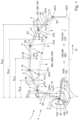
- schematisch ein erfindungsgemäßes System und ein erfindungsgemäßes Verfahren zum automatischen Einstellen einer veränderbaren Maststellung eines verstellbaren Verteilermasts einer Bau- und/oder Dickstoffpumpenvorrichtung, insbesondere einen Zusammenhang zwischen der Maststellung und einem Kippmoment des Verteilermasts,
- Fig. 2
- schematisch ein Blockschaltschild des Systems und des Verfahrens der
Fig. 1 , insbesondere zu einer Minimierung des Kippmoments, und - Fig. 3 bis 10
- schematisch Beispiele für die Funktionsweise des Systems und des Verfahrens der
Fig. 1 . -
Fig. 1 ,2 , und3 bis 10 zeigen ein erfindungsgemäßes System 1, insbesondere aufweisend eine Einstelleinrichtung 2, ausgebildet und ein erfindungsgemäßes Verfahren zum automatischen Einstellen einer veränderbaren Maststellung MS eines verstellbaren Verteilermasts 3 einer Bau- und/oder Dickstoffpumpenvorrichtung 4. Mindestens eine selbe Spitzenposition SPO einer Mastspitze 3S des Verteilermasts 3 ist durch verschiedene Maststellungen MS, MS' erreichbar. - Des Weiteren ist das System 1, insbesondere die Einstellungseinrichtung 2, zum Ermitteln und Einstellen einer Maststellung MS in Abhängigkeit einer vorgegebenen Größe VG bestimmend eine Spitzenposition SPO und anhand eines Optimierungskriteriums OK ausgebildet, insbesondere ermittelt und stellt ein.
- Außerdem weist das Verfahren den Schritt auf: Ermitteln und Einstellen der Maststellung MS in Abhängigkeit der vorgegebenen Größe VG bestimmend die Spitzenposition SPO und anhand des Optimierungskriteriums OK, insbesondere mittels des Systems 1, insbesondere der Einstellungseinrichtung 2.
- Das Optimierungskriterium OK ist ein minimiertes Kippmoment KM des Verteilermasts 3 in Bezug auf ein Abstützungssystem 7 der Bau- und/oder Dickstoffpumpenvorrichtung 4, insbesondere einen Mastfuß 3F des Verteilermasts 3. Das Kippmoment KM hängt von der Maststellung MS ab.
- In dem gezeigten Ausführungsbeispiel weist das System 1 den Verteilermast 3, insbesondere die Bau- und/oder Dickstoffpumpenvorrichtung 4, auf.
- Im Detail weist der Verteilermast 3 mehrere verstellbare Mastgelenke 5a, 5b, 5c, 5d, 5e auf. Die Maststellung MS ist durch eine veränderbare Gelenkstellungs-Kombination GSK der Mastgelenke 5a-e veränderbar. Dieselbe Spitzenposition SPO ist durch verschiedene Gelenkstellungs-Kombinationen GSK, GSK' erreichbar. Insbesondere weisen die Mastgelenke 5a, 5b, 5c, 5d, 5e verschiedene Verstellbereiche 5Va, 5Vb, 5Vc, 5Vd, 5Ve auf. Der Schritt weist auf: Ermitteln und Einstellen einer Gelenkstellungs-Kombination GSK in Abhängigkeit der vorgegebenen Größe VG und anhand des Optimierungskriteriums OK, insbesondere und unter Berücksichtigung der Verstellbereiche 5Va-e, insbesondere mittels des Systems 1, insbesondere der Einstellungseinrichtung 2. Das Kippmoment KM hängt von der Gelenkstellungs-Kombination GSK ab.
- Im Detail ist der Verteilermast 3 mittels der Mastgelenke 5a-e Roll- und/oder Z-faltbar, insbesondere Roll-Z-faltbar.
- Weiter weist der Verteilermast 3 mehrere, insbesondere zueinander, verstellbare Mastsegmente 6a, 6b, 6c, 6d, 6e auf. Die Maststellung MS ist durch eine veränderbare Verstellungs-Kombination VSK der Mastsegmente 6a-e, insbesondere zueinander, veränderbar. Dieselbe Spitzenposition SPO ist durch verschiedene Verstellungs-Kombinationen VSK, VSK' erreichbar. Insbesondere weisen die Mastsegmente 6a, 6b, 6c, 6d, 6e verschiedene Massen ma, mb, mc, md, me und/oder verschiedene Längen La, Lb, Lc, Ld, Le und/oder verschiedene Schwerpunktspositionen GPa, GPb, GPc, GPd, GPe auf. Der Schritt weist auf: Ermitteln und Einstellen einer Verstellungs-Kombination VSK in Abhängigkeit der vorgegebenen Größe VG und anhand des Optimierungskriteriums OK, insbesondere und unter Berücksichtigung der Massen ma-e und/oder der Längen La-e und/oder der Schwerpunktspositionen GPa-e, insbesondere mittels des Systems 1, insbesondere der Einstellungseinrichtung 2. Das Kippmoment KM hängt von der Verstellungs-Kombination VSK ab.
- In dem gezeigten Ausführungsbeispiel weist der Verteilermast 3 fünf verstellbare Mastgelenke 5a-e auf. In alternativen Ausführungsbeispielen kann der Verteilermast mindestens drei Mastgelenke aufweisen.
- Zudem weist in dem gezeigten Ausführungsbeispiel der Verteilermast 3 fünf Mastsegmente 6a-e auf. In alternativen Ausführungsbeispielen kann der Verteilermast mindestens drei Mastsegmente aufweisen.
- Zum Hintergrund: Ein Mastgelenk und/oder ein Mastsegment ermöglichen/ermöglicht eine Bewegung der Mastspitze. Zwei Mastgelenke und/oder zwei Mastsegmente ermöglichen eine freie Bewegung der Mastspitze, insbesondere wobei Höhe und Radius, insbesondere in gewissen Grenzen, voneinander unabhängig sind. Mindestens drei Mastgelenke und/oder mindestens drei Mastsegmente ermöglichen eine freie Bewegung der Mastspitze und eine Einstellung der Maststellung über mindestens einen Freiheitsgrad. In anderen Worten: N Mastgelenke und/oder N Mastsegmente mit N >= drei ermöglichen eine freie Bewegung der Mastspitze und eine Einstellung der Maststellung über N-zwei Freiheitsgrade.
- Des Weiteren sind/ist in dem gezeigten Ausführungsbeispiel ein Radius bzw. ein Abstand r und/oder eine Richtung bzw. ein Winkel RI des Verteilermasts 3, insbesondere seiner Mastspitze 3S, insbesondere in Bezug auf seinen Mastfuß 3F und/oder das Abstützungssystem 7, durch die veränderbare Gelenkstellungs-Kombination GSK und/oder die veränderbare Verstellungs-Kombination VSK veränderbar.
- Außerdem weist der Schritt auf: Ermitteln und Einstellen einer Veränderung VMS ausgehend von einer Ist-Maststellung IMS basierend auf einer, insbesondere größten, Minimierung ausgehend von einem Ist-Kippmoment IKM des Verteilermasts 3 in Bezug auf das Abstützungssystem 7, insbesondere mittels des Systems 1, insbesondere der Einstellungseinrichtung 2. Das Ist-Kippmoment IKM hängt von der Ist-Maststellung IMS ab.
- Zum Hintergrund: das Kippmoment KM, insbesondere das Ist-Kippmoment IKM, insbesondere eine Funktion des Kippmoments KM in Abhängigkeit der Maststellung MS, ist z.B.:

- g.. Erdbeschleunigung

- lG,i.. Hebelarm für die Gewichtskraft von Mastsegment i
- mi .. Masse von Mastsegment i
- Hebelarme der Mastsegmente 6a-e sind abhängig von der Maststellung MS, insbesondere der Ist-Maststellung IMS, z.B.:


- Insbesondere größte, Minimierung des Kippmoments KM, insbesondere ausgehend von dem Ist-Kippmoment IKM, bedeutet z.B. Ableitung der Funktion des Kippmoments KM nach der Veränderung VMS der Maststellung MS, insbesondere der Verstellkoordinate bzw. der Winkel der Mastgelenke 5a-e, insbesondere ausgehend von der Ist-Maststellung IMS:


- Ein Ermitteln, insbesondere ein Bestimmen, von Geschwindigkeiten der Mastgelenke 5a-e, insbesondere nur bzw. rein, zur Minimierung des Kippmoments KM ist z.B. über Pseudoinverse bzw. eine inverse direkte Kinematik möglich:

- Weiter weist der Schritt auf: Steuern, insbesondere Regeln, der Maststellung MS zu einer Erreichung und/oder einer Haltung der Spitzenposition SPO, insbesondere einer Soll-Spitzenposition SSPO, insbesondere ausgehend von einer Ist-Spitzenposition ISPO des Verteilermasts 3 und/oder während des Ermittelns und des Einstellens der Veränderung VMS und/oder solange das Ist-Kippmoment IKM minimiert wird, insbesondere mittels des Systems 1, insbesondere der Einstellungseinrichtung 2.
- Zum Hintergrund: Erreichen und/oder Halten, insbesondere Festhalten, der Mastspitze 3S z.B. über einen Regler, insbesondere der Einstelleinrichtung 2.
- Eine Abweichung der Spitzenposition SPO, insbesondere der Ist-Spitzenposition ISPO, von der Soll-Spitzenposition bzw. dem Sollwert SSPO führt auf einen Positionsfehler z.B.:

- Um den Positionsfehler zu minimieren kann oder soll eine Bewegung der Mastspitze 3S auf die Soll-Spitzenposition SSPO zu eingeleitet werden, z.B. über eine einfaches proportionales Regelgesetz:

- Eine Abbildung auf die Geschwindigkeiten der Mastgelenke 5a-e ist z.B. über den Zusammenhang möglich:

- Zudem weist der Schritt auf: Ermitteln und Einstellen der Veränderung VMS und Steuern, insbesondere Regeln, der Maststellung MS mittels Ermittelns einer Lösung LS für einen kinematischen Zusammenhang KIZ der Minimierung des Ist-Kippmoments IKM und der Erreichung und/oder der Haltung der Spitzenposition SPO miteinander, insbesondere mittels des Systems 1, insbesondere der Einstellungseinrichtung 2.
- Zum Hintergrund: die letzte genannte Funktion bzw. Forderung kann mit der Minimierung des Kippmoments KM, insbesondere dieser Funktion bzw. Forderung, z.B. durch die Vektorgleichung


- Um mindestens einen, insbesondere alle, der Verstellbereiche 5Va-e zu berücksichtigen, kann z.B. in Abhängigkeit einer Gelenkstellung GS eines der Mastgelenke 5a-e ein Fahr- bzw. Bewegungsbefehl in den, insbesondere zugehörigen, Verstellbereich 5Va-e hinein gefordert werden. Ist z.B. der Winkel des ersten Mastgelenks 5a, insbesondere an dem Mastfuß 3F, in der Nähe eines Grenzwerts, kann zusätzlich z.B.:

- Mit dieser zusätzlichen Forderung bzw. Bedingung bzw. Funktion ergibt sich der kinematische Zusammenhang KIZ, insbesondere Gesamtzusammenhang, bzw. die kombinierte Jacobi-Matrix:

- Dieser kinematische Zusammenhang KIZ stellt ein überbestimmtes Gleichungssystem dar, das im Allgemeinen nicht exakt gelöst werden kann. Stattdessen kann z.B. die beste Lösung LS dieses Gleichungssystems im Sinne der kleinsten Fehlerquadrate ermittelt werden. Dafür kann eine Summe der Quadrate der Fehler in der obigen Gleichung minimiert werden. Das Kostenfunktional dieser Optimierung ist dabei:

- Um die einzelnen Bestandteile des Verfahrens bzw. Vorgangs (Minimierung des Kippmoments KM, Erreichung und/oder Haltung der Soll-Spitzenposition SSPO und die Umsetzung der geforderten Geschwindigkeiten der Mastgelenke 5a-e), insbesondere verschieden, priorisieren zu können, können diese mit verschiedenen Gewichtungen im Kostenfunktional K berücksichtigt werden. Die Diagonalmatrix W kann diese Gewichte aufweisen, insbesondere enthalten.
- Da es sich um einen linearen Zusammenhang handelt, kann dieser z.B. direkt über eine allgemeine Least-Squares Lösung erfolgen:

- Alternativ, insbesondere und in diesem bzw. dem vorliegenden Fall vorteilhaft, kann die Minimierung des Kostenfunktionals auch iterativ anhand seines Gradienten:

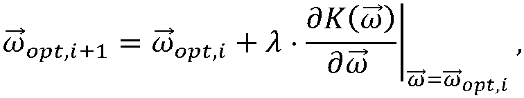
ω opt,0, der im einfachsten Fall einfach gleich dem Nullvektor gewählt werden kann. - Des Weiteren ist das Abstützungssystem 7 verstellbar. Das Verfahren weist den Schritt auf: Sperren von Maststellungen MS" und/oder Kippmomenten KM" in Abhängigkeit einer ermittelten Größe EG bestimmend mindestens eine veränderbare Abstützkonfiguration ASK des verstellbaren Abstützungssystems 7 zur Entgegenwirkung des Kippmoments KM, insbesondere mittels des Systems 1, insbesondere der Einstellungseinrichtung 2.
- Außerdem weist der Verteilermast 3 eine Förderleitung 8 zur Förderung von Bau- und/oder Dickstoff BDS auf, insbesondere fördert.
- Im Übrigen weist der Verteilermast 3 einen, insbesondere frei hängenden, Endschlauch auf.
- Insbesondere kann der Endschlauch bei der Masse me und/oder der Schwerpunktsposition GPe des, insbesondere letzten, Mastsegments 6e berücksichtigt werden.
- Wie die gezeigten und oben erläuterten Ausführungsbeispiele deutlich machen, stellt die Erfindung ein vorteilhaftes Verfahren zum automatischen Einstellen einer veränderbaren Maststellung eines verstellbaren Verteilermasts einer Bau- und/oder Dickstoffpumpenvorrichtung und ein vorteilhaftes System bereit, insbesondere das jeweils verbesserte Eigenschaften aufweist.
- In anderen Worten: das Verfahren und/oder das System zur automatischen Minimierung des Kippmoments ermöglichen/ermöglicht dem Bediener bzw. Benutzer die maximale Ausnutzung des Arbeitsraums bei einer Freigabe des Arbeitsraums auf Basis des Ist-Kippmoments. Beim Erreichen der Grenze des freigegebenen Arbeitsraums kann der Verteilermast durch einen einfachen Knopfdruck derart umgestellt werden, dass das Ist-Kippmoment minimiert wird, wodurch weitere Teile des Arbeitsraums freigegeben werden. Dadurch wird dem Bediener bzw. Benutzer ohne eigene Kenntnis zu den Zusammenhängen zwischen Kippmoment und Maststellung ermöglicht, die Bau- und/oder Dickstoffpumpenvorrichtung im maximal möglichen Bereich bei minimaler Abstützbreite zu betreiben.
Claims (7)
- Verfahren zum automatischen Einstellen einer veränderbaren Maststellung (MS) eines verstellbaren Verteilermasts (3) einer Bau- und/oder Dickstoffpumpenvorrichtung (4), wobei mindestens eine selbe Spitzenposition (SPO) einer Mastspitze (3S) des Verteilermasts (3) durch verschiedene Maststellungen (MS, MS') erreichbar ist, wobei das Verfahren den Schritt aufweist:- Ermitteln und Einstellen, mittels einer Einstellungseinrichtung (2), einer Maststellung (MS) in Abhängigkeit einer vorgegebenen Größe (VG) bestimmend eine Spitzenposition (SPO) und anhand eines Optimierungskriteriums (OK), wobei das Optimierungskriterium (OK) ein minimiertes Kippmoment (KM) des Verteilermasts (3) in Bezug auf ein Abstützungssystem (7) der Bau- und/oder Dickstoffpumpenvorrichtung (4) ist, wobei das Kippmoment (KM) von der Maststellung (MS) abhängt,
dadurch gekennzeichnet, dass- der Schritt aufweist: Ermitteln und Einstellen, mittels der Einstellungseinrichtung (2), einer Veränderung (VMS) ausgehend von einer Ist-Maststellung (IMS) basierend auf einer, insbesondere größten, Minimierung ausgehend von einem Ist-Kippmoment (IKM) des Verteilermasts (3) in Bezug auf das Abstützungssystem (7), wobei das Ist-Kippmoment (IKM) von der Ist-Maststellung (IMS) abhängt,- wobei der Schritt aufweist: Steuern, insbesondere Regeln, ,mittels der Einstellungseinrichtung (2), der Maststellung (MS) zu einer Erreichung und/oder einer Haltung der Spitzenposition (SPO), insbesondere ausgehend von der Ist-Spitzenposition (ISPO) des Verteilermasts (3) und/oder während des Ermittelns und des Einstellens der Veränderung (VMS) und/oder solange das Ist-Kippmoment (IKM) minimiert wird, und- wobei der Schritt aufweist: Ermitteln und Einstellen, mittels der Einstellungseinrichtung (2), der Veränderung (VMS) und Steuern, insbesondere Regeln, der Maststellung (MS) mittels Ermittelns einer Lösung (LS) für einen kinematischen Zusammenhang (KIZ) der Minimierung des Ist-Kippmoments (IKM) und der Erreichung und/oder der Haltung der Spitzenposition (SPO) miteinander. - Verfahren nach Anspruch 1,- wobei der Verteilermast (3) mehrere verstellbare Mastgelenke (5a, 5b, 5c, 5d, 5e) aufweist, wobei die Maststellung (MS) durch eine veränderbare Gelenkstellungs-Kombination (GSK) der Mastgelenke (5a-e) veränderbar ist, wobei dieselbe Spitzenposition (SPO) durch verschiedene Gelenkstellungs-Kombinationen (GSK, GSK') erreichbar ist, insbesondere wobei die Mastgelenke (5a, 5b, 5c, 5d, 5e) verschiedene Verstellbereiche (5Va, 5Vb, 5Vc, 5Vd, 5Ve) aufweisen,- wobei der Schritt aufweist: Ermitteln und Einstellen einer Gelenkstellungs-Kombination (GSK) in Abhängigkeit der vorgegebenen Größe (VG) und anhand des Optimierungskriteriums (OK), wobei das Kippmoment (KM) von der Gelenkstellungs-Kombination (GSK) abhängt, insbesondere und unter Berücksichtigung der Verstellbereiche (5Va-e).
- Verfahren nach Anspruch 2,- wobei der Verteilermast (3) mittels der Mastgelenke (5a-e) Roll- und/oder Z-faltbar, insbesondere Roll-Z-faltbar, ist.
- Verfahren nach einem der vorhergehenden Ansprüche,- wobei der Verteilermast (3) mehrere, insbesondere zueinander, verstellbare Mastsegmente (6a, 6b, 6c, 6d, 6e) aufweist, wobei die Maststellung (MS) durch eine veränderbare Verstellungs-Kombination (VSK) der Mastsegmente (6a-e), insbesondere zueinander, veränderbar ist, wobei dieselbe Spitzenposition (SPO) durch verschiedene Verstellungs-Kombinationen (VSK, VSK') erreichbar ist, insbesondere wobei die Mastsegmente (6a, 6b, 6c, 6d, 6e) verschiedene Massen (ma, mb, mc, md, me) und/oder verschiedene Längen (La, Lb, Lc, Ld, Le) und/oder verschiedene Schwerpunktspositionen (GPa, GPb, GPc, GPd, GPe) aufweisen,- wobei der Schritt aufweist: Ermitteln und Einstellen einer Verstellungs-Kombination (VSK) in Abhängigkeit der vorgegebenen Größe (VG) und anhand des Optimierungskriteriums (OK), wobei das Kippmoment (KM) von der Verstellungs-Kombination (VSK) abhängt, insbesondere und unter Berücksichtigung der Massen (mae) und/oder der Längen (La-e) und/oder der Schwerpunktspositionen (GPa-e).
- Verfahren nach einem der vorhergehenden Ansprüche,- wobei das Abstützungssystem (7) verstellbar ist,- wobei das Verfahren den Schritt aufweist: Sperren von Maststellungen (MS") und/oder Kippmomenten (KM") in Abhängigkeit einer ermittelten Größe (EG) bestimmend mindestens eine veränderbare Abstützkonfiguration (ASK) des verstellbaren Abstützungssystems (7) zur Entgegenwirkung des Kippmoments (KM).
- Verfahren nach einem der vorhergehenden Ansprüche,- wobei der Verteilermast (3) eine Förderleitung (8) zur Förderung von Bau- und/oder Dickstoff (BDS) aufweist.
- System (1), insbesondere zum Ausführen eines Verfahrens nach einem der vorhergehenden Ansprüche, wobei das System (1) aufweist:- eine Einstellungseinrichtung (2),- wobei die Einstellungseinrichtung (2) zum automatischen Einstellen einer veränderbaren Maststellung (MS) eines verstellbaren Verteilermasts (3) einer Bau- und/oder Dickstoffpumpenvorrichtung (4) ausgebildet ist, wobei mindestens eine selbe Spitzenposition (SPO) einer Mastspitze (3S) des Verteilermasts (3) durch verschiedene Maststellungen (MS, MS') erreichbar ist,- wobei die Einstellungseinrichtung (2) zum Ermitteln und Einstellen einer Maststellung (MS) in Abhängigkeit einer vorgegebenen Größe (VG) bestimmend eine Spitzenposition (SPO) und anhand eines Optimierungskriteriums (OK) ausgebildet ist, wobei das Optimierungskriterium (OK) ein minimiertes Kippmoment (KM) des Verteilermasts (3) in Bezug auf ein Abstützungssystem (7) der Bau- und/oder Dickstoffpumpenvorrichtung (4) ist, wobei das Kippmoment (KM) von der Maststellung (MS) abhängt, dadurch gekennzeichnet, dass- die Einstellungseinrichtung (2) zum Ermitteln und Einstellen einer Veränderung (VMS) ausgehend von einer Ist-Maststellung (IMS) basierend auf einer, insbesondere größten, Minimierung ausgehend von einem Ist-Kippmoment (IKM) des Verteilermasts (3) in Bezug auf das Abstützungssystem (7) ausgebildet ist, wobei das Ist-Kippmoment (IKM) von der Ist-Maststellung (IMS) abhängt,- wobei die Einstellungseinrichtung (2) zum Steuern, insbesondere Regeln, der Maststellung (MS) zu einer Erreichung und/oder einer Haltung der Spitzenposition (SPO), insbesondere ausgehend von der Ist-Spitzenposition (ISPO) des Verteilermasts (3) und/oder während des Ermittelns und des Einstellens der Veränderung (VMS) und/oder solange das Ist-Kippmoment (IKM) minimiert wird, ausgebildet ist, und- wobei die Einstellungseinrichtung (2) zum Ermitteln und Einstellen der Veränderung (VMS) und zum Steuern, insbesondere Regeln, der Maststellung (MS) mittels Ermittelns einer Lösung (LS) für einen kinematischen Zusammenhang (KIZ) der Minimierung des Ist-Kippmoments (IKM) und der Erreichung und/oder der Haltung der Spitzenposition (SPO) miteinander ausgebildet ist.
Priority Applications (1)
| Application Number | Priority Date | Filing Date | Title |
|---|---|---|---|
| EP25157640.1A EP4530419A1 (de) | 2021-07-06 | 2022-06-29 | Verfahren zum automatischen einstellen einer veränderbaren maststellung eines verstellbaren verteilermasts einer bau- und/oder dickstoffpumpenvorrichtung und system |
Applications Claiming Priority (2)
| Application Number | Priority Date | Filing Date | Title |
|---|---|---|---|
| DE102021207092.2A DE102021207092A1 (de) | 2021-07-06 | 2021-07-06 | Verfahren zum automatischen Einstellen einer veränderbaren Maststellung eines verstellbaren Verteilermasts einer Bau- und/oder Dickstoffpumpenvorrichtung und System |
| PCT/EP2022/067917 WO2023280657A1 (de) | 2021-07-06 | 2022-06-29 | Verfahren zum automatischen einstellen einer veränderbaren maststellung eines verstellbaren verteilermasts einer bau- und/oder dickstoffpumpenvorrichtung und system |
Related Child Applications (2)
| Application Number | Title | Priority Date | Filing Date |
|---|---|---|---|
| EP25157640.1A Division EP4530419A1 (de) | 2021-07-06 | 2022-06-29 | Verfahren zum automatischen einstellen einer veränderbaren maststellung eines verstellbaren verteilermasts einer bau- und/oder dickstoffpumpenvorrichtung und system |
| EP25157640.1A Division-Into EP4530419A1 (de) | 2021-07-06 | 2022-06-29 | Verfahren zum automatischen einstellen einer veränderbaren maststellung eines verstellbaren verteilermasts einer bau- und/oder dickstoffpumpenvorrichtung und system |
Publications (2)
| Publication Number | Publication Date |
|---|---|
| EP4367347A1 EP4367347A1 (de) | 2024-05-15 |
| EP4367347B1 true EP4367347B1 (de) | 2025-03-26 |
Family
ID=82446523
Family Applications (2)
| Application Number | Title | Priority Date | Filing Date |
|---|---|---|---|
| EP22738466.6A Active EP4367347B1 (de) | 2021-07-06 | 2022-06-29 | Verfahren zum automatischen einstellen einer veränderbaren maststellung eines verstellbaren verteilermasts einer bau- und/oder dickstoffpumpenvorrichtung und system |
| EP25157640.1A Pending EP4530419A1 (de) | 2021-07-06 | 2022-06-29 | Verfahren zum automatischen einstellen einer veränderbaren maststellung eines verstellbaren verteilermasts einer bau- und/oder dickstoffpumpenvorrichtung und system |
Family Applications After (1)
| Application Number | Title | Priority Date | Filing Date |
|---|---|---|---|
| EP25157640.1A Pending EP4530419A1 (de) | 2021-07-06 | 2022-06-29 | Verfahren zum automatischen einstellen einer veränderbaren maststellung eines verstellbaren verteilermasts einer bau- und/oder dickstoffpumpenvorrichtung und system |
Country Status (7)
| Country | Link |
|---|---|
| US (1) | US20240287822A1 (de) |
| EP (2) | EP4367347B1 (de) |
| JP (1) | JP2024525570A (de) |
| KR (1) | KR20240028471A (de) |
| CN (1) | CN117616184A (de) |
| DE (1) | DE102021207092A1 (de) |
| WO (1) | WO2023280657A1 (de) |
Family Cites Families (13)
| Publication number | Priority date | Publication date | Assignee | Title |
|---|---|---|---|---|
| JPS62225661A (ja) * | 1986-03-27 | 1987-10-03 | 株式会社竹中工務店 | コンクリ−ト分配装置の操縦方法 |
| JPH0741790Y2 (ja) * | 1990-12-26 | 1995-09-27 | 株式会社新潟鉄工所 | ブーム付コンクリートポンプ車における釣合い機構 |
| JP2002195208A (ja) * | 2000-12-28 | 2002-07-10 | Mitsubishi Heavy Ind Ltd | ブームを備えた車両 |
| DE10328769A1 (de) * | 2003-06-25 | 2005-01-20 | Putzmeister Ag | Knickmast für fahrbare Betonpumpen |
| DE102008017961A1 (de) * | 2008-04-08 | 2009-10-15 | Putzmeister Concrete Pumps Gmbh | Betonpumpe mit einer Steuereinheit für die Verteilermastbewegung und einer Regeleinheit für die Fördermengenregelung |
| CN102588505B (zh) | 2012-02-06 | 2014-01-15 | 三一汽车制造有限公司 | 泵车稳定性控制系统、控制方法及泵车 |
| DE102014215019A1 (de) * | 2014-07-30 | 2016-02-04 | Putzmeister Engineering Gmbh | Autobetonpumpe und Verfahren zu deren Arbeitsbetrieb |
| DE102016125450B4 (de) * | 2016-12-22 | 2025-12-31 | Schwing Gmbh | Fahrbarer Großmanipulator |
| CN106842954B (zh) * | 2017-03-14 | 2020-07-03 | 北京理工大学 | 一种半柔性机械臂系统的控制方法 |
| CN108098777B (zh) * | 2018-01-12 | 2021-04-30 | 华侨大学 | 一种冗余度机械臂力矩层重复运动控制方法 |
| CN108326852B (zh) * | 2018-01-16 | 2021-01-05 | 西北工业大学 | 一种多目标优化的空间机械臂轨迹规划方法 |
| DE102019105817A1 (de) | 2019-03-07 | 2020-09-10 | Liebherr-Mischtechnik Gmbh | Gelenkarm-Steuerung einer Betonpumpe |
| CN112157650B (zh) * | 2020-08-17 | 2022-10-25 | 盐城工学院 | 车载机械臂动力学建模与控制方法 |
-
2021
- 2021-07-06 DE DE102021207092.2A patent/DE102021207092A1/de active Pending
-
2022
- 2022-06-29 CN CN202280048184.1A patent/CN117616184A/zh active Pending
- 2022-06-29 JP JP2024500269A patent/JP2024525570A/ja active Pending
- 2022-06-29 KR KR1020247003629A patent/KR20240028471A/ko active Pending
- 2022-06-29 US US18/576,777 patent/US20240287822A1/en active Pending
- 2022-06-29 EP EP22738466.6A patent/EP4367347B1/de active Active
- 2022-06-29 EP EP25157640.1A patent/EP4530419A1/de active Pending
- 2022-06-29 WO PCT/EP2022/067917 patent/WO2023280657A1/de not_active Ceased
Also Published As
| Publication number | Publication date |
|---|---|
| JP2024525570A (ja) | 2024-07-12 |
| CN117616184A (zh) | 2024-02-27 |
| US20240287822A1 (en) | 2024-08-29 |
| EP4367347A1 (de) | 2024-05-15 |
| EP4530419A1 (de) | 2025-04-02 |
| WO2023280657A1 (de) | 2023-01-12 |
| KR20240028471A (ko) | 2024-03-05 |
| DE102021207092A1 (de) | 2023-01-12 |
Similar Documents
| Publication | Publication Date | Title |
|---|---|---|
| EP4013713B1 (de) | Kran und verfahren zum steuern eines solchen krans | |
| EP3733512B1 (de) | Verfahren und vorrichtung zum heben einer last | |
| DE69025471T2 (de) | Verfahren und vorrichtung zur steuerung des abbremsens der drehbewegung des oberen drehteils von baumaschinen und rechengerät zur ermittlung des neigungswinkels | |
| EP3559374B1 (de) | Grossmanipulator mit automatisiertem mastaufbau | |
| EP2502871B1 (de) | Kransteuerung, Kran und Verfahren | |
| EP1537282B1 (de) | Grossmanipulator mit einem Knickmast und einer Regeleinrichtung zur Aussteuerung des Knickmastes | |
| EP4501839A2 (de) | Kran und verfahren zum steuern eines solchen krans | |
| DE102017114789A1 (de) | Kran und Verfahren zum Steuern eines solchen Krans | |
| EP3303732B1 (de) | Grossmanipulator mit schnell ein- und ausfaltbarem knickmast | |
| AT520008B1 (de) | Verfahren zum Dämpfen von Drehschwingungen eines Lastaufnahmeelements einer Hebeeinrichtung | |
| DE102012220036A1 (de) | Bewegungssystem, das ausgestaltet ist, um eine nutzlast inmehrere richtungen zu bewegen | |
| EP1992583A2 (de) | Kransteuerung, Kran und Verfahren | |
| EP3953287B1 (de) | Vorrichtung zur steuerung einer an einem strang hängenden last | |
| DE102015100669A1 (de) | Anti-pendel-steuerverfahren mit einstellbarer unterstützung für den transport einer schwebenden last | |
| DE102014012457B4 (de) | Automatisches Aufrichten eines Krans | |
| EP4367347B1 (de) | Verfahren zum automatischen einstellen einer veränderbaren maststellung eines verstellbaren verteilermasts einer bau- und/oder dickstoffpumpenvorrichtung und system | |
| EP2151585B1 (de) | Dämpfungsvorrichtung für einen Manipulator | |
| DE102010054502A1 (de) | Verfahren und Vorrichtung zur Positionierung einer an einer Seilaufhängung einer Krananlage hängenden Kranlast in Rotationsrichtung um deren vertikale Achse | |
| EP1834920B1 (de) | Verfahren zum automatischen Umschlagen von einer Last eines Kranes mit Lastpendelungsdämpfung und Bahnplaner | |
| EP3366430B1 (de) | Fördervorrichtung zum befördern von objekten und/oder personen | |
| EP4190739B1 (de) | Verfahren zum regeln einer bewegung einer last in einem arbeitsraum einer lastentransporteinrichtung | |
| DE102021107139A1 (de) | Betriebsüberwachung für ein Dickstofffördersystem | |
| EP0321789B1 (de) | Einrichtung zur Steuerung des Niveauausgleichs eines Arbeitsgerätes, insbesondere einer fahrbaren höhenverstellbaren Feuerwehrdrehleiter | |
| WO2023280656A1 (de) | Verfahren und system zum steuern einer bewegung eines verstellbaren verteilermasts und verfahren zum verteilen von bau- und/oder dickstoff mittels einer bau- und/oder dickstoffpumpenvorrichtung aufweisend einen verstellbaren verteilermast | |
| DE102021128317A1 (de) | Verfahren und System zur Planung eines Einsatzes zum Heben einer Last mit einem Kran |
Legal Events
| Date | Code | Title | Description |
|---|---|---|---|
| STAA | Information on the status of an ep patent application or granted ep patent |
Free format text: STATUS: UNKNOWN |
|
| STAA | Information on the status of an ep patent application or granted ep patent |
Free format text: STATUS: THE INTERNATIONAL PUBLICATION HAS BEEN MADE |
|
| PUAI | Public reference made under article 153(3) epc to a published international application that has entered the european phase |
Free format text: ORIGINAL CODE: 0009012 |
|
| STAA | Information on the status of an ep patent application or granted ep patent |
Free format text: STATUS: REQUEST FOR EXAMINATION WAS MADE |
|
| 17P | Request for examination filed |
Effective date: 20240117 |
|
| AK | Designated contracting states |
Kind code of ref document: A1 Designated state(s): AL AT BE BG CH CY CZ DE DK EE ES FI FR GB GR HR HU IE IS IT LI LT LU LV MC MK MT NL NO PL PT RO RS SE SI SK SM TR |
|
| GRAP | Despatch of communication of intention to grant a patent |
Free format text: ORIGINAL CODE: EPIDOSNIGR1 |
|
| STAA | Information on the status of an ep patent application or granted ep patent |
Free format text: STATUS: GRANT OF PATENT IS INTENDED |
|
| DAV | Request for validation of the european patent (deleted) | ||
| DAX | Request for extension of the european patent (deleted) | ||
| INTG | Intention to grant announced |
Effective date: 20241014 |
|
| GRAS | Grant fee paid |
Free format text: ORIGINAL CODE: EPIDOSNIGR3 |
|
| GRAA | (expected) grant |
Free format text: ORIGINAL CODE: 0009210 |
|
| STAA | Information on the status of an ep patent application or granted ep patent |
Free format text: STATUS: THE PATENT HAS BEEN GRANTED |
|
| AK | Designated contracting states |
Kind code of ref document: B1 Designated state(s): AL AT BE BG CH CY CZ DE DK EE ES FI FR GB GR HR HU IE IS IT LI LT LU LV MC MK MT NL NO PL PT RO RS SE SI SK SM TR |
|
| REG | Reference to a national code |
Ref country code: GB Ref legal event code: FG4D Free format text: NOT ENGLISH |
|
| REG | Reference to a national code |
Ref country code: CH Ref legal event code: EP |
|
| REG | Reference to a national code |
Ref country code: DE Ref legal event code: R096 Ref document number: 502022003350 Country of ref document: DE |
|
| REG | Reference to a national code |
Ref country code: IE Ref legal event code: FG4D Free format text: LANGUAGE OF EP DOCUMENT: GERMAN |
|
| PG25 | Lapsed in a contracting state [announced via postgrant information from national office to epo] |
Ref country code: RS Free format text: LAPSE BECAUSE OF FAILURE TO SUBMIT A TRANSLATION OF THE DESCRIPTION OR TO PAY THE FEE WITHIN THE PRESCRIBED TIME-LIMIT Effective date: 20250626 |
|
| PG25 | Lapsed in a contracting state [announced via postgrant information from national office to epo] |
Ref country code: FI Free format text: LAPSE BECAUSE OF FAILURE TO SUBMIT A TRANSLATION OF THE DESCRIPTION OR TO PAY THE FEE WITHIN THE PRESCRIBED TIME-LIMIT Effective date: 20250326 |
|
| PGFP | Annual fee paid to national office [announced via postgrant information from national office to epo] |
Ref country code: DE Payment date: 20250624 Year of fee payment: 4 |
|
| REG | Reference to a national code |
Ref country code: LT Ref legal event code: MG9D |
|
| PG25 | Lapsed in a contracting state [announced via postgrant information from national office to epo] |
Ref country code: NO Free format text: LAPSE BECAUSE OF FAILURE TO SUBMIT A TRANSLATION OF THE DESCRIPTION OR TO PAY THE FEE WITHIN THE PRESCRIBED TIME-LIMIT Effective date: 20250626 |
|
| PG25 | Lapsed in a contracting state [announced via postgrant information from national office to epo] |
Ref country code: HR Free format text: LAPSE BECAUSE OF FAILURE TO SUBMIT A TRANSLATION OF THE DESCRIPTION OR TO PAY THE FEE WITHIN THE PRESCRIBED TIME-LIMIT Effective date: 20250326 |
|
| PG25 | Lapsed in a contracting state [announced via postgrant information from national office to epo] |
Ref country code: LV Free format text: LAPSE BECAUSE OF FAILURE TO SUBMIT A TRANSLATION OF THE DESCRIPTION OR TO PAY THE FEE WITHIN THE PRESCRIBED TIME-LIMIT Effective date: 20250326 |
|
| PG25 | Lapsed in a contracting state [announced via postgrant information from national office to epo] |
Ref country code: GR Free format text: LAPSE BECAUSE OF FAILURE TO SUBMIT A TRANSLATION OF THE DESCRIPTION OR TO PAY THE FEE WITHIN THE PRESCRIBED TIME-LIMIT Effective date: 20250627 Ref country code: BG Free format text: LAPSE BECAUSE OF FAILURE TO SUBMIT A TRANSLATION OF THE DESCRIPTION OR TO PAY THE FEE WITHIN THE PRESCRIBED TIME-LIMIT Effective date: 20250326 |
|
| PGFP | Annual fee paid to national office [announced via postgrant information from national office to epo] |
Ref country code: AT Payment date: 20250721 Year of fee payment: 4 |
|
| PGFP | Annual fee paid to national office [announced via postgrant information from national office to epo] |
Ref country code: TR Payment date: 20250625 Year of fee payment: 4 |
|
| REG | Reference to a national code |
Ref country code: NL Ref legal event code: MP Effective date: 20250326 |
|
| PG25 | Lapsed in a contracting state [announced via postgrant information from national office to epo] |
Ref country code: NL Free format text: LAPSE BECAUSE OF FAILURE TO SUBMIT A TRANSLATION OF THE DESCRIPTION OR TO PAY THE FEE WITHIN THE PRESCRIBED TIME-LIMIT Effective date: 20250326 |
|
| PG25 | Lapsed in a contracting state [announced via postgrant information from national office to epo] |
Ref country code: SE Free format text: LAPSE BECAUSE OF FAILURE TO SUBMIT A TRANSLATION OF THE DESCRIPTION OR TO PAY THE FEE WITHIN THE PRESCRIBED TIME-LIMIT Effective date: 20250326 |
|
| PG25 | Lapsed in a contracting state [announced via postgrant information from national office to epo] |
Ref country code: SM Free format text: LAPSE BECAUSE OF FAILURE TO SUBMIT A TRANSLATION OF THE DESCRIPTION OR TO PAY THE FEE WITHIN THE PRESCRIBED TIME-LIMIT Effective date: 20250326 |
|
| PG25 | Lapsed in a contracting state [announced via postgrant information from national office to epo] |
Ref country code: PT Free format text: LAPSE BECAUSE OF FAILURE TO SUBMIT A TRANSLATION OF THE DESCRIPTION OR TO PAY THE FEE WITHIN THE PRESCRIBED TIME-LIMIT Effective date: 20250728 Ref country code: ES Free format text: LAPSE BECAUSE OF FAILURE TO SUBMIT A TRANSLATION OF THE DESCRIPTION OR TO PAY THE FEE WITHIN THE PRESCRIBED TIME-LIMIT Effective date: 20250326 |
|
| PG25 | Lapsed in a contracting state [announced via postgrant information from national office to epo] |
Ref country code: PL Free format text: LAPSE BECAUSE OF FAILURE TO SUBMIT A TRANSLATION OF THE DESCRIPTION OR TO PAY THE FEE WITHIN THE PRESCRIBED TIME-LIMIT Effective date: 20250326 |
|
| PGFP | Annual fee paid to national office [announced via postgrant information from national office to epo] |
Ref country code: IT Payment date: 20250630 Year of fee payment: 4 |
|
| PG25 | Lapsed in a contracting state [announced via postgrant information from national office to epo] |
Ref country code: EE Free format text: LAPSE BECAUSE OF FAILURE TO SUBMIT A TRANSLATION OF THE DESCRIPTION OR TO PAY THE FEE WITHIN THE PRESCRIBED TIME-LIMIT Effective date: 20250326 |
|
| PG25 | Lapsed in a contracting state [announced via postgrant information from national office to epo] |
Ref country code: RO Free format text: LAPSE BECAUSE OF FAILURE TO SUBMIT A TRANSLATION OF THE DESCRIPTION OR TO PAY THE FEE WITHIN THE PRESCRIBED TIME-LIMIT Effective date: 20250326 |
|
| PG25 | Lapsed in a contracting state [announced via postgrant information from national office to epo] |
Ref country code: SK Free format text: LAPSE BECAUSE OF FAILURE TO SUBMIT A TRANSLATION OF THE DESCRIPTION OR TO PAY THE FEE WITHIN THE PRESCRIBED TIME-LIMIT Effective date: 20250326 |
|
| PG25 | Lapsed in a contracting state [announced via postgrant information from national office to epo] |
Ref country code: IS Free format text: LAPSE BECAUSE OF FAILURE TO SUBMIT A TRANSLATION OF THE DESCRIPTION OR TO PAY THE FEE WITHIN THE PRESCRIBED TIME-LIMIT Effective date: 20250726 |
|
| REG | Reference to a national code |
Ref country code: DE Ref legal event code: R097 Ref document number: 502022003350 Country of ref document: DE |
|
| PG25 | Lapsed in a contracting state [announced via postgrant information from national office to epo] |
Ref country code: DK Free format text: LAPSE BECAUSE OF FAILURE TO SUBMIT A TRANSLATION OF THE DESCRIPTION OR TO PAY THE FEE WITHIN THE PRESCRIBED TIME-LIMIT Effective date: 20250326 |
|
| PG25 | Lapsed in a contracting state [announced via postgrant information from national office to epo] |
Ref country code: CZ Free format text: LAPSE BECAUSE OF FAILURE TO SUBMIT A TRANSLATION OF THE DESCRIPTION OR TO PAY THE FEE WITHIN THE PRESCRIBED TIME-LIMIT Effective date: 20250326 |
|
| REG | Reference to a national code |
Ref country code: CH Ref legal event code: H13 Free format text: ST27 STATUS EVENT CODE: U-0-0-H10-H13 (AS PROVIDED BY THE NATIONAL OFFICE) Effective date: 20260127 |
|
| PG25 | Lapsed in a contracting state [announced via postgrant information from national office to epo] |
Ref country code: MC Free format text: LAPSE BECAUSE OF FAILURE TO SUBMIT A TRANSLATION OF THE DESCRIPTION OR TO PAY THE FEE WITHIN THE PRESCRIBED TIME-LIMIT Effective date: 20250326 |
|
| PLBE | No opposition filed within time limit |
Free format text: ORIGINAL CODE: 0009261 |
|
| STAA | Information on the status of an ep patent application or granted ep patent |
Free format text: STATUS: NO OPPOSITION FILED WITHIN TIME LIMIT |
|
| REG | Reference to a national code |
Ref country code: CH Ref legal event code: L10 Free format text: ST27 STATUS EVENT CODE: U-0-0-L10-L00 (AS PROVIDED BY THE NATIONAL OFFICE) Effective date: 20260211 |
|
| PG25 | Lapsed in a contracting state [announced via postgrant information from national office to epo] |
Ref country code: LU Free format text: LAPSE BECAUSE OF NON-PAYMENT OF DUE FEES Effective date: 20250629 |
|
| REG | Reference to a national code |
Ref country code: BE Ref legal event code: MM Effective date: 20250630 |
|
| 26N | No opposition filed |
Effective date: 20260105 |