EP4368016B1 - Élément de tension de fil pour contrôler séparément la tension de deux fils - Google Patents
Élément de tension de fil pour contrôler séparément la tension de deux fils Download PDFInfo
- Publication number
- EP4368016B1 EP4368016B1 EP23207137.3A EP23207137A EP4368016B1 EP 4368016 B1 EP4368016 B1 EP 4368016B1 EP 23207137 A EP23207137 A EP 23207137A EP 4368016 B1 EP4368016 B1 EP 4368016B1
- Authority
- EP
- European Patent Office
- Prior art keywords
- wire
- engagement
- tensioning element
- wires
- teeth
- Prior art date
- Legal status (The legal status is an assumption and is not a legal conclusion. Google has not performed a legal analysis and makes no representation as to the accuracy of the status listed.)
- Active
Links
Images





Classifications
-
- A—HUMAN NECESSITIES
- A01—AGRICULTURE; FORESTRY; ANIMAL HUSBANDRY; HUNTING; TRAPPING; FISHING
- A01G—HORTICULTURE; CULTIVATION OF VEGETABLES, FLOWERS, RICE, FRUIT, VINES, HOPS OR SEAWEED; FORESTRY; WATERING
- A01G17/00—Cultivation of hops, vines, fruit trees, or like trees
- A01G17/04—Supports for hops, vines, or trees
- A01G17/06—Trellis-work
-
- A—HUMAN NECESSITIES
- A01—AGRICULTURE; FORESTRY; ANIMAL HUSBANDRY; HUNTING; TRAPPING; FISHING
- A01G—HORTICULTURE; CULTIVATION OF VEGETABLES, FLOWERS, RICE, FRUIT, VINES, HOPS OR SEAWEED; FORESTRY; WATERING
- A01G17/00—Cultivation of hops, vines, fruit trees, or like trees
- A01G17/04—Supports for hops, vines, or trees
- A01G17/06—Trellis-work
- A01G2017/065—Trellis-work for supporting vines having wire-tensioning devices
Definitions
- the present invention relates to an agricultural wire-tensioning element, to a device or elastic compensating element comprising said element and a system for supporting rows of plants including such wire tensioning element.
- the invention relates to a wire tensioning roller provided with a structure that is advantageously adapted to separately adjust the tension of two wires.
- connection wires are commonly referred to as “containment wires” or “movable wires” given that, during the various stages of plant cultivation, they are moved to different heights from the ground to contain and organise the growing vegetation according to a desired configuration.
- movable wires are arranged close to the ground.
- each pair of movable wires is placed progressively further away from the ground in the direction orthogonal to the ground, harnessing the vegetation between the wires of each pair, therefore organising the development thereof according to a desired configuration.
- This operation is commonly carried out to ensure an increasing exposure of the foliar surface and the fruits of the plants to the sun and wind. Furthermore, this facilitates vegetation treatment operations such as clipping, plant protection treatments and other fully conventional treatments.
- rollers In particular, the tensioning of fixed or movable wires is carried out by means of tensioning elements or wire tensioners generally represented by rollers.
- These rollers shall consist of a rod with a cylindrical cross-section and/or at least partly solid or hollow polygonal and provided with transversal holes for engagement with one or more ends of metal wires to be tensioned.
- transversal holes for engagement with one or more ends of metal wires to be tensioned.
- a further object is to provide an elastically compensating device comprising the aforementioned wire tensioning element, as well as a system for supporting rows of plants comprising the aforementioned wire tensioning element.
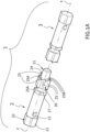
- the first portion 2 is generally cylindrical bar-shaped comprising a first end 20 and a second end 21 opposite the first.
- the first end 20 is provided with means 22 for engagement with a tool (not shown) for driving the first portion in rotation around the axis X-X.
- a tool not shown
- such means are a hexagonal surface which can be engaged by a corresponding hollow hexagon head tightening wrench.
- the engagement means may be a through hole which can be engaged by a rod, such as the shank of a screwdriver.
- the first portion 2 comprises a through hole 23 for engagement with an end segment of a wire to be tensioned, as explained below.
- the second end 21 is a pin which extends axially and represents a first means for engagement with a complementary second engagement means obtained on the second portion 3, as described below.
- the pin 21 has a radial extension that is smaller than the rest of the first portion 2 so as to create a radial ring 24.
- such ring 24 shall be serrated and shaped so as to cooperate with a corresponding complementary serrated ring entirely obtained on the second portion 3, so as to allow the rotation of each of the portions, first 2 and second 3 around the axis X-X only in one direction, clockwise or counter-clockwise, this however preventing the mutual rotation in the opposite direction, counter-clockwise or clockwise. Therefore, the two serrated rings of the respective first 2 and second 3 portions of the roller 1 face for an axial engagement, as explained in greater detail below.
- teeth 25 of the ring 24 are radially inclined in a single direction to form a ring in which there are alternated a shoulder 25A of a tooth and a ramp 25B of an adjacent tooth.
- the teeth are inclined with respect to the direction orthogonal to the axis X-X.
- the number of teeth may vary depending on particular needs or preferences. Preferably, there are six of them, they have a radial extension of 60° and a 5°-40° degree of inclination with respect to the X-X axis.
- the second portion 3 of the roller 1, as shown in figure 1B has a shape generally identical to that of the first portion 2, with a first end 30 and a second end 31.
- the first end 30 is provided with means 32 for engagement with a tool (not shown) for driving the second portion in rotation around the axis X-X.
- a tool not shown
- such means are a hexagonal surface which can be engaged by a corresponding hollow hexagon head tightening wrench.
- the means may be a through hole which can be engaged by a rod, such as the shank of a screwdriver.
- the second portion 3 comprises a through hole 33 for engagement with an end segment of a wire to be tensioned, as explained below.
- the teeth are inclined with respect to the direction orthogonal to the axis X-X.
- the number of teeth may vary depending on particular needs or preferences. Preferably, there are six of them, they have a radial extension of 60° and a 5°-40° degree of inclination with respect to the X-X axis.
- the radial surface 37 of the teeth 36 extends axially towards the first end 30 with a polygonal shape, preferably hexagonal, followed by an annular seat 38 for engagement with the edge of a hole of a post (not shown) for supporting a row of plants.
- Said seat allows the roller 1 of the invention to be rotatably supported by a support post, when provided for, also at its second portion 3 for greater stability.
- the two portions are assembled by inserting the pin 21 of the first portion into cavity 34 of the second portion so that the annular step 24 and the radial edge 35 come into contact with the ramps and shoulders of the respective teeth in complementary contact.
- figure 3 shows an elastically compensating device 100 or damper comprising the tensioning element 1 described above.
- the elastically compensating device 100 is substantially a device like the one described for example in patent EP 1699286 and it comprises an elastic element 5 which extends along a rectilinear axis Z-Z between a first 6 and a second 7 hook-like element.
- the elastic element 5 is preferably a compressible spring between said first 6 and second 7 hook-like elements, which extends between a first 50 and a second 51 end.
- the first hook-like element 6 comprises a first end 60 for fixing to a post (not shown) of a row head, a second end 61 for retaining the second end 51 of the elastic element 5 and a straight section 62 which connects said ends and it is such to be inserted into the internal space defined by said elastic element.
- said first hook-like element is formed by a metal wire folded to form a U shape in which the first end 60 protrudes from the first end 50 of the elastic element 5, it is closed and variously shaped to be connected directly around said post or indirectly using a collar or further connection means such as for example a chain, or using a screw transversal to the post.
- the second end 61 of said first hook-like element comprises two portions of wire 63 which are folded divergently so as to create two hooks for engagement with at least one turn of said second end 51 of the elastic element.
- the second hook-like element 7 comprises a first end 70 for supporting the wire tensioning element 1 of the invention, a second end 71 for retaining the first end 50 of the elastic element 5 and a straight section 72 between said first and second end adapted to be inserted into the internal space defined by said elastic element.
- said second hook-like element is formed by a metal wire folded to form a U shape in which the first end 70 forms two parallel foldings 73 each for engagement with an annular seat 27, 38 respectively of the first 2 and second 3 portion of the wire tensioning element 1.
- the second end 71 comprises two portions 74 (only one visible in figure 3 ) of a wire folded divergently so as to create two hooks for engagement with at least one turn of said first end 50 of the elastic element 5.
- the wire tensioning element 1 is fitted, for example, to the first end 70 for supporting the second hook-like element 7 of an elastically compensating device 100 so that the parallel foldings 73 each engage a seat 27, 38 respectively of the first portion 2 and of the second portion 3 of the wire tensioning element ( figure 3 ).
- a metal wire (and not only, for example also plastic) W is inserted into each through hole 23, 33 respectively of the first 2 and second 3 portion.
- one of the two portions of the wire tensioning element 1 is driven in rotation by engaging with an appropriate tool (not shown) which acts on the first end 30 thereof.
- an appropriate tool (not shown) which acts on the first end 30 thereof.
- the engagement described above allows to wind the wire W on the second portion, leaving the first portion 2 still, preferably held still using a further tool which engages the first end 20 thereof, for greater safety, bringing the wire to the desired tension.
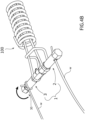
- the first end 20 of the first portion 2 can be adjusted to wind and therefore tension another wire W thereon ( figure 4C ).
- the rotation occurs is in the opposite direction with respect to the rotation direction of the second portion 3.
- the wire tensioning element 1 of the invention is mounted on the aforementioned elastically compensating device 100 so that, during the tensioning of the wires ( figures 4B and 4C ), the elastic element 5 is partially compressed.
- this completely conventional operation can be carried out separately for the two wires so as to adjust not only the tension individually but also as a result any asymmetries which can easily appear between the two wires W.
- the wire tensioning element 1 may be arranged inclined with respect to the longitudinal extension of the wires W, both on the vertical and horizontal plane.
- the elastic element 5 of the elastically compensating device 100 could easily twist with greater shortening of the turns on one side with respect to the other and, therefore, negatively affect its correct functionality.
- the wire tensioning element 1 can be mounted, for example, directly on a support post thanks to the engagement between the edges of two holes on opposite walls and the two circular seats 27 and 38 respectively of the first 2 and second 3 portion.
- figure 5 schematically shows a system 11 for supporting the vegetation of a fruit-bearing plants-row, preferably for a vineyard, comprising two head posts P fixed into the ground with suitable fixing means F known in the industry, such as tensioners and the respective anchors. Driven into the ground between said head posts are intermediate posts I arranged in line and evenly spaced apart from each other so as to form a row.
- a plurality of wires are fixed to the head posts P and they are generally divided into fixed wires W1 and movable wires W2. Both the fixed and movable wires can be tensioned using the tensioning element 1 of the present invention.
- the movable wires are fixed to the head posts using elastically compensating elements 100.
Landscapes
- Life Sciences & Earth Sciences (AREA)
- Botany (AREA)
- Environmental Sciences (AREA)
- Supports For Plants (AREA)
Claims (9)
- - Élément (1) de tension de fil agricole comprenant une première partie (2) assemblée à une seconde partie (3) le long d'un axe (X-X) rectiligne commun afin d'autoriser la rotation mutuelle autour dudit axe, ledit élément de tension de fil agricole étant caractérisé par le fait que ladite rotation est contrainte dans un unique sens pour chaque partie au moyen d'un engagement entre un anneau radial (24) denté de ladite première partie et un anneau radial (35) denté, en miroir, de ladite seconde partie, dont les dents (25 ; 36) respectives sont radialement inclinées par rapport audit axe (X-X) selon un unique sens de façon à former un accouplement de forme entre les dents des première (2) et seconde (3) parties.
- - Élément (1) selon la revendication 1, dans lequel lesdites dents (25 ; 36) sont formées par un épaulement (25A ; 36A) et une rampe (25B ; 36B) qui sont alternés l'un par rapport à l'autre.
- - Élément (1) selon la revendication 1 ou 2, dans lequel ladite première partie (2) comprend une première extrémité (20) pour un engagement avec un outil pour l'entraînement en rotation de celle-ci et une seconde extrémité axiale en forme de cheville (21), et dans lequel ladite seconde partie (3) comprend une première extrémité (30) pour un engagement avec un outil pour l'entraînement en rotation de celle-ci et une seconde extrémité (32) comportant une cavité axiale (34) pour un engagement avec ladite cheville (21) de ladite première partie.
- - Élément (1) selon la revendication 3, dans lequel ledit anneau radial (24) de ladite première partie (2) est obtenu à la base de ladite cheville (21) et ledit anneau radial (35) de ladite seconde partie (3) est obtenu autour de l'ouverture de ladite cavité (34).
- - Élément (1) selon la revendication 3 ou 4, dans lequel, à proximité des premières extrémités (20 ; 30) de chaque première (2) et seconde (3) parties, un trou traversant (23 ; 33) est réalisé pour un engagement avec un fil (W) à tendre.
- - Élément (1) selon l'une quelconque des revendications 3 à 5, comprenant en outre un siège circulaire (27 ; 38) obtenu à proximité de chacune desdites secondes extrémités (21; 31) respectivement desdites première (2) et seconde (3) parties.
- - Dispositif à compensation élastique (100) comprenant un élément (1) de tension de fil agricole selon l'une quelconque des revendications 1 à 6.
- - Piquet agricole comprenant un élément (1) de tension de fil agricole selon l'une quelconque des revendications 1 à 6.
- - Système (11) pour supporter la végétation d'une rangée de plantes fruitières comprenant deux piquets de tête (P) fixés dans le sol à l'aide de moyens de fixation (F), des piquets intermédiaires (I) disposés en ligne et espacés de manière régulière entre lesdits piquets de tête, une pluralité de fils fixes (W1) et de fils mobiles (W2) fixés et tendus auxdits piquets de tête à l'aide de l'élément (1) de tension selon l'une quelconque des revendications 1 à 6.
Priority Applications (1)
| Application Number | Priority Date | Filing Date | Title |
|---|---|---|---|
| HRP20250786TT HRP20250786T1 (hr) | 2022-11-11 | 2023-10-31 | Element za zatezanje žice za odvojeno kontroliranje napetosti dvije žice |
Applications Claiming Priority (1)
| Application Number | Priority Date | Filing Date | Title |
|---|---|---|---|
| IT102022000023298A IT202200023298A1 (it) | 2022-11-11 | 2022-11-11 | Elemento tendifilo per regolare separatamente la tensione di due fili |
Publications (2)
| Publication Number | Publication Date |
|---|---|
| EP4368016A1 EP4368016A1 (fr) | 2024-05-15 |
| EP4368016B1 true EP4368016B1 (fr) | 2025-04-16 |
Family
ID=85018555
Family Applications (1)
| Application Number | Title | Priority Date | Filing Date |
|---|---|---|---|
| EP23207137.3A Active EP4368016B1 (fr) | 2022-11-11 | 2023-10-31 | Élément de tension de fil pour contrôler séparément la tension de deux fils |
Country Status (3)
| Country | Link |
|---|---|
| EP (1) | EP4368016B1 (fr) |
| HR (1) | HRP20250786T1 (fr) |
| IT (1) | IT202200023298A1 (fr) |
Family Cites Families (6)
| Publication number | Priority date | Publication date | Assignee | Title |
|---|---|---|---|---|
| DE3336574A1 (de) * | 1983-10-07 | 1985-04-25 | Otto Gerock, Spritz- und Preßgußfabrik GmbH & Co, 7100 Heilbronn | Drahtspanner |
| ITPN20030082A1 (it) | 2003-11-24 | 2005-05-25 | Bortolussi Mollificio Srl | Tendifilo con compensazione elastica particolarmente |
| ITPN20050087A1 (it) | 2005-11-28 | 2007-05-29 | Bortolussi Mollificio Srl | Dispositivo tendifilo. |
| IT1397102B1 (it) * | 2009-11-23 | 2012-12-28 | Bortolussi | Dispositivo di compensazione elastica, in particolare per fili di un filare di piante |
| ITPN20120021A1 (it) * | 2012-04-23 | 2013-10-24 | Bortolussi Mollificio Srl | Procedimento per produrre un rullino tendifilo e rullino ottenuto con tale procedimento |
| DE102014004160B3 (de) * | 2014-03-22 | 2015-03-19 | Carl Stahl Gmbh | Einrichtung zum Spannen von Strangelementen |
-
2022
- 2022-11-11 IT IT102022000023298A patent/IT202200023298A1/it unknown
-
2023
- 2023-10-31 EP EP23207137.3A patent/EP4368016B1/fr active Active
- 2023-10-31 HR HRP20250786TT patent/HRP20250786T1/hr unknown
Also Published As
| Publication number | Publication date |
|---|---|
| IT202200023298A1 (it) | 2024-05-11 |
| HRP20250786T1 (hr) | 2025-09-12 |
| EP4368016A1 (fr) | 2024-05-15 |
Similar Documents
| Publication | Publication Date | Title |
|---|---|---|
| US6293521B1 (en) | Systems for positioning and tensioning wires in trellis systems for vineyards | |
| US7571567B2 (en) | Resiliently compensated wire tensioner particularly for use in the field of vine growing | |
| US20180288951A1 (en) | Adjustable trellis system | |
| EP4368016B1 (fr) | Élément de tension de fil pour contrôler séparément la tension de deux fils | |
| EP3672396B1 (fr) | Dispositif de compensation élastique amélioré pour rangées de plantes et procédé d'utilisation de celui-ci | |
| US20170118924A1 (en) | Line attachment mechanism and systems and methods for using the same | |
| US5630292A (en) | Support apparatus | |
| AU1547702A (en) | An assembly for training plants, in particular vines | |
| EP2324700B1 (fr) | Tendeur à fil à compensation élastique notamment pour des fils des plantes rangées. | |
| EP3716755B1 (fr) | Dispositif de mise sous tension de fils de support de plantes, système de support desdites plantes comprenant un tel dispositif et son procédé de support | |
| EP2244550B1 (fr) | Élément d'espacement du type à ressort | |
| EP4578273A1 (fr) | Dispositif simplifié de compensation élastique pour la tension du fil de soutien des plantes, système de soutien de ces plantes comprenant ce dispositif et méthode de soutien correspondante | |
| EP2324701B1 (fr) | Système d'attachement | |
| EP4578274A1 (fr) | Dispositif de compensation élastique amélioré pour la tension du fil de support des plantes, système de support pour lesdites plantes comprenant un tel dispositif et méthode de support connexe | |
| KR102788239B1 (ko) | 줄기 작물을 이동 및 내림시키는 이송 장치 | |
| ES3035794T3 (en) | Practical tool for fastening a reversible wire blocking element on a support rod for plants | |
| ES2278811T3 (es) | Herramienta de instalacion de correa. | |
| CN102884960A (zh) | 金属丝型的绿化用材料及其设置方法 | |
| KR20240001797U (ko) | 고리형 농작물 지지구 | |
| KR20260000995A (ko) | 이송유닛을 활용한 과채류 줄기 이동 내림 작업 자동화 시스템 | |
| EP2324697A1 (fr) | Dispositif de fixation | |
| Studer et al. | The production and field installation of cordon coils |
Legal Events
| Date | Code | Title | Description |
|---|---|---|---|
| REG | Reference to a national code |
Ref country code: HR Ref legal event code: TUEP Ref document number: P20250786T Country of ref document: HR |
|
| PUAI | Public reference made under article 153(3) epc to a published international application that has entered the european phase |
Free format text: ORIGINAL CODE: 0009012 |
|
| STAA | Information on the status of an ep patent application or granted ep patent |
Free format text: STATUS: THE APPLICATION HAS BEEN PUBLISHED |
|
| AK | Designated contracting states |
Kind code of ref document: A1 Designated state(s): AL AT BE BG CH CY CZ DE DK EE ES FI FR GB GR HR HU IE IS IT LI LT LU LV MC ME MK MT NL NO PL PT RO RS SE SI SK SM TR |
|
| P01 | Opt-out of the competence of the unified patent court (upc) registered |
Effective date: 20240523 |
|
| STAA | Information on the status of an ep patent application or granted ep patent |
Free format text: STATUS: REQUEST FOR EXAMINATION WAS MADE |
|
| 17P | Request for examination filed |
Effective date: 20240926 |
|
| RBV | Designated contracting states (corrected) |
Designated state(s): AL AT BE BG CH CY CZ DE DK EE ES FI FR GB GR HR HU IE IS IT LI LT LU LV MC ME MK MT NL NO PL PT RO RS SE SI SK SM TR |
|
| D17P | Request for examination filed (deleted) | ||
| GRAP | Despatch of communication of intention to grant a patent |
Free format text: ORIGINAL CODE: EPIDOSNIGR1 |
|
| STAA | Information on the status of an ep patent application or granted ep patent |
Free format text: STATUS: GRANT OF PATENT IS INTENDED |
|
| R17P | Request for examination filed (corrected) |
Effective date: 20240926 |
|
| RBV | Designated contracting states (corrected) |
Designated state(s): AL AT BE BG CH CY CZ DE DK EE ES FI FR GB GR HR HU IE IS IT LI LT LU LV MC ME MK MT NL NO PL PT RO RS SE SI SK SM TR |
|
| INTG | Intention to grant announced |
Effective date: 20241111 |
|
| GRAS | Grant fee paid |
Free format text: ORIGINAL CODE: EPIDOSNIGR3 |
|
| GRAA | (expected) grant |
Free format text: ORIGINAL CODE: 0009210 |
|
| STAA | Information on the status of an ep patent application or granted ep patent |
Free format text: STATUS: THE PATENT HAS BEEN GRANTED |
|
| AK | Designated contracting states |
Kind code of ref document: B1 Designated state(s): AL AT BE BG CH CY CZ DE DK EE ES FI FR GB GR HR HU IE IS IT LI LT LU LV MC ME MK MT NL NO PL PT RO RS SE SI SK SM TR |
|
| REG | Reference to a national code |
Ref country code: GB Ref legal event code: FG4D |
|
| REG | Reference to a national code |
Ref country code: CH Ref legal event code: EP Ref country code: DE Ref legal event code: R096 Ref document number: 602023002957 Country of ref document: DE |
|
| REG | Reference to a national code |
Ref country code: IE Ref legal event code: FG4D |
|
| REG | Reference to a national code |
Ref country code: NL Ref legal event code: MP Effective date: 20250416 |
|
| REG | Reference to a national code |
Ref country code: HR Ref legal event code: T1PR Ref document number: P20250786 Country of ref document: HR |
|
| PG25 | Lapsed in a contracting state [announced via postgrant information from national office to epo] |
Ref country code: NL Free format text: LAPSE BECAUSE OF FAILURE TO SUBMIT A TRANSLATION OF THE DESCRIPTION OR TO PAY THE FEE WITHIN THE PRESCRIBED TIME-LIMIT Effective date: 20250416 |
|
| REG | Reference to a national code |
Ref country code: AT Ref legal event code: MK05 Ref document number: 1784846 Country of ref document: AT Kind code of ref document: T Effective date: 20250416 |
|
| PG25 | Lapsed in a contracting state [announced via postgrant information from national office to epo] |
Ref country code: PT Free format text: LAPSE BECAUSE OF FAILURE TO SUBMIT A TRANSLATION OF THE DESCRIPTION OR TO PAY THE FEE WITHIN THE PRESCRIBED TIME-LIMIT Effective date: 20250818 Ref country code: FI Free format text: LAPSE BECAUSE OF FAILURE TO SUBMIT A TRANSLATION OF THE DESCRIPTION OR TO PAY THE FEE WITHIN THE PRESCRIBED TIME-LIMIT Effective date: 20250416 Ref country code: ES Free format text: LAPSE BECAUSE OF FAILURE TO SUBMIT A TRANSLATION OF THE DESCRIPTION OR TO PAY THE FEE WITHIN THE PRESCRIBED TIME-LIMIT Effective date: 20250416 |
|
| REG | Reference to a national code |
Ref country code: LT Ref legal event code: MG9D |
|
| PG25 | Lapsed in a contracting state [announced via postgrant information from national office to epo] |
Ref country code: NO Free format text: LAPSE BECAUSE OF FAILURE TO SUBMIT A TRANSLATION OF THE DESCRIPTION OR TO PAY THE FEE WITHIN THE PRESCRIBED TIME-LIMIT Effective date: 20250716 Ref country code: GR Free format text: LAPSE BECAUSE OF FAILURE TO SUBMIT A TRANSLATION OF THE DESCRIPTION OR TO PAY THE FEE WITHIN THE PRESCRIBED TIME-LIMIT Effective date: 20250717 |
|
| PG25 | Lapsed in a contracting state [announced via postgrant information from national office to epo] |
Ref country code: PL Free format text: LAPSE BECAUSE OF FAILURE TO SUBMIT A TRANSLATION OF THE DESCRIPTION OR TO PAY THE FEE WITHIN THE PRESCRIBED TIME-LIMIT Effective date: 20250416 |
|
| PG25 | Lapsed in a contracting state [announced via postgrant information from national office to epo] |
Ref country code: BG Free format text: LAPSE BECAUSE OF FAILURE TO SUBMIT A TRANSLATION OF THE DESCRIPTION OR TO PAY THE FEE WITHIN THE PRESCRIBED TIME-LIMIT Effective date: 20250416 |
|
| PG25 | Lapsed in a contracting state [announced via postgrant information from national office to epo] |
Ref country code: AT Free format text: LAPSE BECAUSE OF FAILURE TO SUBMIT A TRANSLATION OF THE DESCRIPTION OR TO PAY THE FEE WITHIN THE PRESCRIBED TIME-LIMIT Effective date: 20250416 |
|
| PG25 | Lapsed in a contracting state [announced via postgrant information from national office to epo] |
Ref country code: RS Free format text: LAPSE BECAUSE OF FAILURE TO SUBMIT A TRANSLATION OF THE DESCRIPTION OR TO PAY THE FEE WITHIN THE PRESCRIBED TIME-LIMIT Effective date: 20250716 |
|
| PG25 | Lapsed in a contracting state [announced via postgrant information from national office to epo] |
Ref country code: IS Free format text: LAPSE BECAUSE OF FAILURE TO SUBMIT A TRANSLATION OF THE DESCRIPTION OR TO PAY THE FEE WITHIN THE PRESCRIBED TIME-LIMIT Effective date: 20250816 |
|
| PG25 | Lapsed in a contracting state [announced via postgrant information from national office to epo] |
Ref country code: LV Free format text: LAPSE BECAUSE OF FAILURE TO SUBMIT A TRANSLATION OF THE DESCRIPTION OR TO PAY THE FEE WITHIN THE PRESCRIBED TIME-LIMIT Effective date: 20250416 |
|
| REG | Reference to a national code |
Ref country code: HR Ref legal event code: ODRP Ref document number: P20250786 Country of ref document: HR Payment date: 20251023 Year of fee payment: 3 |
|
| PGFP | Annual fee paid to national office [announced via postgrant information from national office to epo] |
Ref country code: DE Payment date: 20251021 Year of fee payment: 3 |
|
| PG25 | Lapsed in a contracting state [announced via postgrant information from national office to epo] |
Ref country code: DK Free format text: LAPSE BECAUSE OF FAILURE TO SUBMIT A TRANSLATION OF THE DESCRIPTION OR TO PAY THE FEE WITHIN THE PRESCRIBED TIME-LIMIT Effective date: 20250416 Ref country code: SM Free format text: LAPSE BECAUSE OF FAILURE TO SUBMIT A TRANSLATION OF THE DESCRIPTION OR TO PAY THE FEE WITHIN THE PRESCRIBED TIME-LIMIT Effective date: 20250416 |
|
| PGFP | Annual fee paid to national office [announced via postgrant information from national office to epo] |
Ref country code: IT Payment date: 20251031 Year of fee payment: 3 |
|
| PGFP | Annual fee paid to national office [announced via postgrant information from national office to epo] |
Ref country code: HR Payment date: 20251023 Year of fee payment: 3 Ref country code: FR Payment date: 20251030 Year of fee payment: 3 |
|
| REG | Reference to a national code |
Ref country code: DE Ref legal event code: R097 Ref document number: 602023002957 Country of ref document: DE |
|
| PG25 | Lapsed in a contracting state [announced via postgrant information from national office to epo] |
Ref country code: CZ Free format text: LAPSE BECAUSE OF FAILURE TO SUBMIT A TRANSLATION OF THE DESCRIPTION OR TO PAY THE FEE WITHIN THE PRESCRIBED TIME-LIMIT Effective date: 20250416 |
|
| PG25 | Lapsed in a contracting state [announced via postgrant information from national office to epo] |
Ref country code: EE Free format text: LAPSE BECAUSE OF FAILURE TO SUBMIT A TRANSLATION OF THE DESCRIPTION OR TO PAY THE FEE WITHIN THE PRESCRIBED TIME-LIMIT Effective date: 20250416 |
|
| PG25 | Lapsed in a contracting state [announced via postgrant information from national office to epo] |
Ref country code: SK Free format text: LAPSE BECAUSE OF FAILURE TO SUBMIT A TRANSLATION OF THE DESCRIPTION OR TO PAY THE FEE WITHIN THE PRESCRIBED TIME-LIMIT Effective date: 20250416 |
|
| PGFP | Annual fee paid to national office [announced via postgrant information from national office to epo] |
Ref country code: RO Payment date: 20251023 Year of fee payment: 3 |
|
| PLBE | No opposition filed within time limit |
Free format text: ORIGINAL CODE: 0009261 |
|
| STAA | Information on the status of an ep patent application or granted ep patent |
Free format text: STATUS: NO OPPOSITION FILED WITHIN TIME LIMIT |
|
| REG | Reference to a national code |
Ref country code: CH Ref legal event code: L10 Free format text: ST27 STATUS EVENT CODE: U-0-0-L10-L00 (AS PROVIDED BY THE NATIONAL OFFICE) Effective date: 20260225 |
|
| 26N | No opposition filed |
Effective date: 20260119 |