EP4578273A1 - Dispositif simplifié de compensation élastique pour la tension du fil de soutien des plantes, système de soutien de ces plantes comprenant ce dispositif et méthode de soutien correspondante - Google Patents
Dispositif simplifié de compensation élastique pour la tension du fil de soutien des plantes, système de soutien de ces plantes comprenant ce dispositif et méthode de soutien correspondante Download PDFInfo
- Publication number
- EP4578273A1 EP4578273A1 EP24218066.9A EP24218066A EP4578273A1 EP 4578273 A1 EP4578273 A1 EP 4578273A1 EP 24218066 A EP24218066 A EP 24218066A EP 4578273 A1 EP4578273 A1 EP 4578273A1
- Authority
- EP
- European Patent Office
- Prior art keywords
- wire
- end portion
- plants
- coil
- wires
- Prior art date
- Legal status (The legal status is an assumption and is not a legal conclusion. Google has not performed a legal analysis and makes no representation as to the accuracy of the status listed.)
- Pending
Links
Images



Classifications
-
- A—HUMAN NECESSITIES
- A01—AGRICULTURE; FORESTRY; ANIMAL HUSBANDRY; HUNTING; TRAPPING; FISHING
- A01G—HORTICULTURE; CULTIVATION OF VEGETABLES, FLOWERS, RICE, FRUIT, VINES, HOPS OR SEAWEED; FORESTRY; WATERING
- A01G17/00—Cultivation of hops, vines, fruit trees, or like trees
- A01G17/04—Supports for hops, vines, or trees
- A01G17/06—Trellis-work
-
- E—FIXED CONSTRUCTIONS
- E04—BUILDING
- E04H—BUILDINGS OR LIKE STRUCTURES FOR PARTICULAR PURPOSES; SWIMMING OR SPLASH BATHS OR POOLS; MASTS; FENCING; TENTS OR CANOPIES, IN GENERAL
- E04H17/00—Fencing, e.g. fences, enclosures, corrals
- E04H17/02—Wire fencing, e.g. made of wire mesh
- E04H17/127—Stretcher-type wire fencing; Tensioning devices for wire fencing
- E04H17/131—Stretcher-type wire fencing; Tensioning devices for wire fencing the wire being tensioned by one or more springs
-
- A—HUMAN NECESSITIES
- A01—AGRICULTURE; FORESTRY; ANIMAL HUSBANDRY; HUNTING; TRAPPING; FISHING
- A01G—HORTICULTURE; CULTIVATION OF VEGETABLES, FLOWERS, RICE, FRUIT, VINES, HOPS OR SEAWEED; FORESTRY; WATERING
- A01G17/00—Cultivation of hops, vines, fruit trees, or like trees
- A01G17/04—Supports for hops, vines, or trees
- A01G17/06—Trellis-work
- A01G2017/065—Trellis-work for supporting vines having wire-tensioning devices
Definitions
- the clamp block also sold under the trade name GRIPPLE ®
- the conical hollow element are particularly valued given that, with a dedicated tool formed by a sort of gripper, they allow for an easy tensioning of the wire and when used individually for an elastically compensating device they do not protrude with respect to the spring.
- the task of the present invention is to provide an elastically compensating device for tensioning wires, in particular for load-bearing wires and movable support wires for vine shoots or plant branches, that overcomes the defects and drawbacks of the devices of the known type like the ones described above.
- Another object is to provide a compensating device for wires which can be mounted on any type of pole for rows of plants irrespective of the shape and size of the cross-section of the pole.
- a further object of the present invention is to provide a device whose overall dimensions do not substantially alter the overall dimensions of the elements on which it is mounted so as not to affect the processing operations especially mechanised along the rows.
- An even further object of the present invention is to provide a device, in particular for movable wires for supporting vine shoots or plant branches, substantially without malfunctions.
- Other objects are a system for supporting plants in rows and a method for supporting plants in rows comprising such device.
- the head poles PE and PI there is fixed at an appropriate height from the ground a fixed wire FM called "load-bearing wire". Furthermore, the head poles are suitably wind-braced by appropriate wind-bracing wires indicated with reference FC.
- the elastically compensating devices 1 On the two head poles PE there are further provided for elastically compensating devices 1 arranged at an appropriate distance from the ground; in the example shown in figure 1 the elastically compensating devices 1 are arranged in a position higher than the one for fixing the load-bearing wire FM.
- a pair of movable wires F which are arranged on both sides of the intermediate poles PI, that is the sides defined by the system.
- the movable wires F may be fixed using simple operations for engaging to suitable support, per se conventional, obtained or applied on the relative intermediate poles PI so as to be positioned at different heights from the ground.
- a numerical symbol was added to the common reference F.
- the position of the wire F3 alone is indicated with a solid line while the others, and precisely the positions of the two lower movable wires and that of the wire above the wire F3, are indicated with dashed lines and respectively with references F1, F2 and F4.
- the movable wires are also called wires for containing the growing vegetation given that in the space defined between them the vegetation is contained and supported during growth.
- each elastically compensating device there may be associated a single wire to be tensioned so as to have individual wires that can be moved independently with respect to each other. In this case, there can be fitted two pole devices on the two sides of the pole.
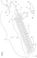
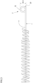
- This device extends along an axis X-X and comprises a first end portion 2 for hooking to a pole, a second end portion 3 opposite to said first end portion, a compression elastic element 4 between said first and second end portion, a seat 5 for engaging with a wire tensioning element 6, wherein said first and second end portion, said elastic element and said seat are formed by a single shaped wire 7 with a first end 8 which is the end of said first end portion, a rectilinear portion 9 which extends from said first end portion and terminates with a first coil 40 which forms said second end portion, a plurality 41 of coils which extend from said first coil around said rectilinear portion forming said elastic element 4, some end coils 42 of said plurality of coils which form said seat 5 axially with respect to the device and terminating with a second end 11 of said single wire 7.
- the device of the invention is advantageous given that with a single duly shaped wire there are obtained all the elements required to perform the function of an elastically compensating element, leaving separated only the tensioning element, which can however be easily engaged and handled with the compensating element.
- the shaped wire 7 is generally made of stainless steel, it has a diameter ranging from 3 mm to 5.5 mm, preferably it measures 3.5 mm and it extends with different segments but without interruptions from the first end 8 to the second end 11.
- the first end portion 2 of the wire comprises the first end 8 and it is shaped so as to allow the engagement to a head pole PE.
- This end portion may be shaped to be engaged to any type of pole.
- the wire-like structure it can be bent to form a ring with one or more coils substantially closed forming an engagement slot with a hook or chain to be applied to a hole, hook or circumference of a pole made of iron, plastic, concrete or wood.
- the end portion as shown in the figures, is formed by a generally hook-shaped bending for engagement with one or more holes of a pole made of steel.
- the bending comprises a first folding 20 generally U-shaped which is the continuation of the rectilinear portion 9 and which lies on a first plane A-A ( figure 4 ) along the axis X-X.
- This U-shape continues with a ring-like bending 21 facing towards one side of the axis X-X and which extends on a plane B-B ( figure 3 ) that is generally orthogonal to said first plane A-A of the first folding.
- Said ring 21 continues with a rectilinear portion 22 which extends toward the device and parallel to the axis X-X terminating with said end 8.
- the plurality of coils 41 terminates with the housing seat 5 for a wire tensioning element 6 of clamping type ( figures 2 and 4 ).
- a wire tensioning element 6 of clamping type ( figures 2 and 4 ).
- such seat is formed by several coils and terminal windings 42 of the plurality of coils 41 such to create a sort of pocket for holding the clamping wire tensioning element 6.
- the seat is formed by a first coil 12 for resting clamped around a segment of the rectilinear portion 9 of the wire 7 and by at least one second containment coil 13. The first coil is closer to the second end portion 3 while at least one second coil terminates with the second end 8 of wire 7.
- the second end portion 3 of the device 1 comprises a second coil 43 which are wound around the rectilinear portion 9 more closely with respect to the first coil and to the subsequent plurality of coils 41.
- This second coil has the function of stabilising the device especially when subjected to particular compressions, for example during the displacements of the wire upwards and downwards with respect to the horizontal position.
- the plurality of coils 41 that is the elastic element 4
- the plurality of coils 41 that is the elastic element 4
- the farming machines could impact the devices bent outwards, with respect to the plane of the row, damaging the devices or the machines.
- the second coil 43 instead, tends to keep the wire stretched near if not adhering to the rectilinear portion, therefore in axis with respect to the compression forces exerted on the elastic part of the device.
- the folding phenomenon mentioned above is significantly limited if not eliminated, with the advantage of avoiding the protruding dangerously with respect to the vertical plane of the system of the vineyard.
- the device may be engaged to a head pole depending on the conformation of the first end portion.
- the end 8 and the rectilinear segment 22 is inserted into an iron pole P through one of its conventional side holes H ( figure 6 ).
- the ring-like bending 21 is inserted with slight inclination into the pole ( figures 7 and 8 ).
- the U-shaped folding 20 is made to be engaged by the edge of the hole of the pole ( figure 9 ). Therefore, the ring 21 and the rectilinear segment 22 in the pole act as a safety hook against accidental removal of the device by the pole.
- a further object of the present invention is a system 100 ( figure 1 ) for supporting rows of plants, comprising at least one end pole PE or head pole secured to the ground using conventional means such as for example concrete bases. Furthermore, the end pole is generally wind-braced using wind-bracing wires FC secured to the ground using conventional anchors.
- a pole driven vertically into the ground through a first profile (not shown) positioned at the upper end portions of said head pole and of the corresponding vertical pole, and possibly through a second section positioned at the lower end portions of said poles driven into the ground so as to constitute a rigid structure which withstands the tension of the wires of the row, as described in patent EP2988589 .
- Fixed wires FM (or load-bearing wires FF as defined in said patent and distinct from the containment wires instead indicated as FM) are fixed to the two end poles PE at a preestablished and unvaried height so as to support the fruit cane of a plant. Furthermore, these wires are maintained at such height from the ground along the entire system due to the engagement with conventional hooks (not shown) obtained on each intermediate pole PI. These hooks are also distributed along the pole so as to ensure different positioning of the movable wires, as usual, so as to follow and support the extension of the vegetation.
- Movable wires F3 are connected, at least at one end portion, to the elastically compensating devices 1 according to the present invention, the devices in turn being fixed to the end poles PE.
- Yet another object of the invention is method for supporting plants along rows, comprising the steps of:
- the single wire device does not require any assembly operation specifically due to the fact that it exits from the forming machine already finished, therefore without additional operations.
Landscapes
- Engineering & Computer Science (AREA)
- Architecture (AREA)
- Life Sciences & Earth Sciences (AREA)
- Civil Engineering (AREA)
- Structural Engineering (AREA)
- Botany (AREA)
- Environmental Sciences (AREA)
- Supports For Plants (AREA)
Applications Claiming Priority (1)
| Application Number | Priority Date | Filing Date | Title |
|---|---|---|---|
| IT102023000028170A IT202300028170A1 (it) | 2023-12-28 | 2023-12-28 | Dispositivo semplificato a compensazione elastica per il tensionamento di fili di sostegno di piante, impianto di sostegno di dette piante comprendente tale dispositivo e relativo metodo di sostegno |
Publications (1)
| Publication Number | Publication Date |
|---|---|
| EP4578273A1 true EP4578273A1 (fr) | 2025-07-02 |
Family
ID=90123002
Family Applications (1)
| Application Number | Title | Priority Date | Filing Date |
|---|---|---|---|
| EP24218066.9A Pending EP4578273A1 (fr) | 2023-12-28 | 2024-12-06 | Dispositif simplifié de compensation élastique pour la tension du fil de soutien des plantes, système de soutien de ces plantes comprenant ce dispositif et méthode de soutien correspondante |
Country Status (2)
| Country | Link |
|---|---|
| EP (1) | EP4578273A1 (fr) |
| IT (1) | IT202300028170A1 (fr) |
Citations (6)
| Publication number | Priority date | Publication date | Assignee | Title |
|---|---|---|---|---|
| US4433831A (en) * | 1982-06-18 | 1984-02-28 | Bunger Richard E | Fence tensioning device |
| EP1699286A2 (fr) | 2003-11-24 | 2006-09-13 | Mollificio Bortolussi S.R.L. | Tendeur a fil a compensation elastique notamment pour viticulture |
| EP2988589A2 (fr) | 2013-04-24 | 2016-03-02 | Claudio Bortolussi | Dispositif pour fixer et régler les fils de support sur une rangée de plantes |
| WO2016102907A1 (fr) | 2014-12-23 | 2016-06-30 | Gripple Limited | Perfectionnements apportés ou se rapportant à des dispositifs de serrage |
| EP3672396A1 (fr) | 2017-08-25 | 2020-07-01 | Franco Bortolussi | Dispositif de compensation élastique amélioré destiné à des rangées de plantes et procédé d'utilisation de celui-ci |
| EP3716755A1 (fr) | 2017-11-27 | 2020-10-07 | Franco Bortolussi | Dispositif de mise sous tension de fils de support de plantes, système de support desdites plantes comprenant un tel dispositif et son procédé de support |
-
2023
- 2023-12-28 IT IT102023000028170A patent/IT202300028170A1/it unknown
-
2024
- 2024-12-06 EP EP24218066.9A patent/EP4578273A1/fr active Pending
Patent Citations (9)
| Publication number | Priority date | Publication date | Assignee | Title |
|---|---|---|---|---|
| US4433831A (en) * | 1982-06-18 | 1984-02-28 | Bunger Richard E | Fence tensioning device |
| EP1699286A2 (fr) | 2003-11-24 | 2006-09-13 | Mollificio Bortolussi S.R.L. | Tendeur a fil a compensation elastique notamment pour viticulture |
| EP1699286B1 (fr) * | 2003-11-24 | 2008-10-15 | Mollificio Bortolussi S.R.L. | Tendeur a fil a compensation elastique notamment pour viticulture |
| EP2988589A2 (fr) | 2013-04-24 | 2016-03-02 | Claudio Bortolussi | Dispositif pour fixer et régler les fils de support sur une rangée de plantes |
| WO2016102907A1 (fr) | 2014-12-23 | 2016-06-30 | Gripple Limited | Perfectionnements apportés ou se rapportant à des dispositifs de serrage |
| EP3672396A1 (fr) | 2017-08-25 | 2020-07-01 | Franco Bortolussi | Dispositif de compensation élastique amélioré destiné à des rangées de plantes et procédé d'utilisation de celui-ci |
| EP3672396B1 (fr) * | 2017-08-25 | 2021-05-26 | Franco Bortolussi | Dispositif de compensation élastique amélioré pour rangées de plantes et procédé d'utilisation de celui-ci |
| EP3716755A1 (fr) | 2017-11-27 | 2020-10-07 | Franco Bortolussi | Dispositif de mise sous tension de fils de support de plantes, système de support desdites plantes comprenant un tel dispositif et son procédé de support |
| EP3716755B1 (fr) * | 2017-11-27 | 2022-07-06 | Franco Bortolussi | Dispositif de mise sous tension de fils de support de plantes, système de support desdites plantes comprenant un tel dispositif et son procédé de support |
Also Published As
| Publication number | Publication date |
|---|---|
| IT202300028170A1 (it) | 2025-06-28 |
Similar Documents
| Publication | Publication Date | Title |
|---|---|---|
| US6293521B1 (en) | Systems for positioning and tensioning wires in trellis systems for vineyards | |
| EP1928224B1 (fr) | Dispositif de levage destiné à un feuillage | |
| US5501035A (en) | Trellis wire support assembly | |
| EP3672396B1 (fr) | Dispositif de compensation élastique amélioré pour rangées de plantes et procédé d'utilisation de celui-ci | |
| EP2988589B1 (fr) | Dispositif pour fixer et régler les fils de support sur une rangée de plantes | |
| EP1699286B1 (fr) | Tendeur a fil a compensation elastique notamment pour viticulture | |
| EP3419410B1 (fr) | Dispositif de support pour un fil de transport d'une rangée de plantes sur un poteau de support | |
| US12317783B2 (en) | Agricultural trellis systems, and associated devices and methods | |
| EP4578273A1 (fr) | Dispositif simplifié de compensation élastique pour la tension du fil de soutien des plantes, système de soutien de ces plantes comprenant ce dispositif et méthode de soutien correspondante | |
| US20050252076A1 (en) | Trellis system | |
| EP4578274A1 (fr) | Dispositif de compensation élastique amélioré pour la tension du fil de support des plantes, système de support pour lesdites plantes comprenant un tel dispositif et méthode de support connexe | |
| EP3716755B1 (fr) | Dispositif de mise sous tension de fils de support de plantes, système de support desdites plantes comprenant un tel dispositif et son procédé de support | |
| EP2324700B1 (fr) | Tendeur à fil à compensation élastique notamment pour des fils des plantes rangées. | |
| EP2324701B1 (fr) | Système d'attachement | |
| EP4363165B1 (fr) | Outil pratique pour fixer un élément de blocage réversible de fil sur un tuteur pour plantes | |
| EP4368016B1 (fr) | Élément de tension de fil pour contrôler séparément la tension de deux fils | |
| EP4110042B1 (fr) | Amélioration de l'élément de verrouillage réversible d'un fil métallique sur un tuteur de plante | |
| WO2020095159A1 (fr) | Élément tendeur de fil amélioré, procédé de production et système de vignoble comprenant cet élément | |
| KR102788239B1 (ko) | 줄기 작물을 이동 및 내림시키는 이송 장치 | |
| EP3272209A1 (fr) | Écarteur pour la mécanisation d'un vignoble et ensemble écarteur-poteau | |
| IT202300023319A1 (it) | Dispositivo reggifilo per pali agricoli | |
| EP2324697A1 (fr) | Dispositif de fixation | |
| Studer et al. | The production and field installation of cordon coils |
Legal Events
| Date | Code | Title | Description |
|---|---|---|---|
| PUAI | Public reference made under article 153(3) epc to a published international application that has entered the european phase |
Free format text: ORIGINAL CODE: 0009012 |
|
| STAA | Information on the status of an ep patent application or granted ep patent |
Free format text: STATUS: THE APPLICATION HAS BEEN PUBLISHED |
|
| AK | Designated contracting states |
Kind code of ref document: A1 Designated state(s): AL AT BE BG CH CY CZ DE DK EE ES FI FR GB GR HR HU IE IS IT LI LT LU LV MC ME MK MT NL NO PL PT RO RS SE SI SK SM TR |
|
| STAA | Information on the status of an ep patent application or granted ep patent |
Free format text: STATUS: REQUEST FOR EXAMINATION WAS MADE |
|
| 17P | Request for examination filed |
Effective date: 20251031 |