EP4368295A1 - Séparateur centrifuge - Google Patents
Séparateur centrifuge Download PDFInfo
- Publication number
- EP4368295A1 EP4368295A1 EP23203123.7A EP23203123A EP4368295A1 EP 4368295 A1 EP4368295 A1 EP 4368295A1 EP 23203123 A EP23203123 A EP 23203123A EP 4368295 A1 EP4368295 A1 EP 4368295A1
- Authority
- EP
- European Patent Office
- Prior art keywords
- central axis
- separation chamber
- centrifugal separator
- section
- outlet channel
- Prior art date
- Legal status (The legal status is an assumption and is not a legal conclusion. Google has not performed a legal analysis and makes no representation as to the accuracy of the status listed.)
- Granted
Links
Images



Classifications
-
- B—PERFORMING OPERATIONS; TRANSPORTING
- B04—CENTRIFUGAL APPARATUS OR MACHINES FOR CARRYING-OUT PHYSICAL OR CHEMICAL PROCESSES
- B04C—APPARATUS USING FREE VORTEX FLOW, e.g. CYCLONES
- B04C5/00—Apparatus in which the axial direction of the vortex is reversed
- B04C5/08—Vortex chamber constructions
- B04C5/081—Shapes or dimensions
-
- B—PERFORMING OPERATIONS; TRANSPORTING
- B04—CENTRIFUGAL APPARATUS OR MACHINES FOR CARRYING-OUT PHYSICAL OR CHEMICAL PROCESSES
- B04C—APPARATUS USING FREE VORTEX FLOW, e.g. CYCLONES
- B04C5/00—Apparatus in which the axial direction of the vortex is reversed
- B04C5/02—Construction of inlets by which the vortex flow is generated, e.g. tangential admission, the fluid flow being forced to follow a downward path by spirally wound bulkheads, or with slightly downwardly-directed tangential admission
- B04C5/04—Tangential inlets
-
- B—PERFORMING OPERATIONS; TRANSPORTING
- B04—CENTRIFUGAL APPARATUS OR MACHINES FOR CARRYING-OUT PHYSICAL OR CHEMICAL PROCESSES
- B04C—APPARATUS USING FREE VORTEX FLOW, e.g. CYCLONES
- B04C5/00—Apparatus in which the axial direction of the vortex is reversed
- B04C5/08—Vortex chamber constructions
- B04C5/103—Bodies or members, e.g. bulkheads, guides, in the vortex chamber
-
- B—PERFORMING OPERATIONS; TRANSPORTING
- B04—CENTRIFUGAL APPARATUS OR MACHINES FOR CARRYING-OUT PHYSICAL OR CHEMICAL PROCESSES
- B04C—APPARATUS USING FREE VORTEX FLOW, e.g. CYCLONES
- B04C5/00—Apparatus in which the axial direction of the vortex is reversed
- B04C5/12—Construction of the overflow ducting, e.g. diffusing or spiral exits
- B04C5/13—Construction of the overflow ducting, e.g. diffusing or spiral exits formed as a vortex finder and extending into the vortex chamber; Discharge from vortex finder otherwise than at the top of the cyclone; Devices for controlling the overflow
-
- B—PERFORMING OPERATIONS; TRANSPORTING
- B04—CENTRIFUGAL APPARATUS OR MACHINES FOR CARRYING-OUT PHYSICAL OR CHEMICAL PROCESSES
- B04C—APPARATUS USING FREE VORTEX FLOW, e.g. CYCLONES
- B04C5/00—Apparatus in which the axial direction of the vortex is reversed
- B04C5/14—Construction of the underflow ducting; Apex constructions; Discharge arrangements ; discharge through sidewall provided with a few slits or perforations
-
- B—PERFORMING OPERATIONS; TRANSPORTING
- B04—CENTRIFUGAL APPARATUS OR MACHINES FOR CARRYING-OUT PHYSICAL OR CHEMICAL PROCESSES
- B04C—APPARATUS USING FREE VORTEX FLOW, e.g. CYCLONES
- B04C5/00—Apparatus in which the axial direction of the vortex is reversed
- B04C5/14—Construction of the underflow ducting; Apex constructions; Discharge arrangements ; discharge through sidewall provided with a few slits or perforations
- B04C5/181—Bulkheads or central bodies in the discharge opening
Definitions
- the invention relates to a centrifugal separator with a housing extending along a central axis, which has a separation chamber wall for delimiting a separation chamber which is fed by an inlet channel for multiphase fluid, wherein a central dip tube is provided for discharging a first fluid phase (light fraction) and an outlet channel is provided for discharging a second fluid phase (heavy fraction), wherein between the separation chamber and the outlet channel an expansion chamber is provided which is expanded radially outwardly with respect to the separation chamber and is delimited radially outwardly by an expansion chamber wall.
- centrifugal separators are generally used to separate fluid phases of different densities (so-called light fraction or heavy fraction) of a multiphase fluid by separating the heavy fraction.
- the multiphase fluid is fed into the separation chamber via an inlet channel and guided in such a way that a rotational flow is formed within the separation chamber.
- the centrifugal forces that occur cause a radial acceleration, in particular of the heavy fraction, and the separation of the heavy fraction on the inside of a separation chamber wall.
- the components of the heavy fraction are transported away and slide in particular on spiral tracks along the inside of the separation chamber wall in the direction of the expansion chamber until they are absorbed in the expansion chamber. There, the rotational movement slows down and the heavy fraction is discharged from the centrifugal separator via an outlet channel connected to the expansion chamber.
- the separation chamber of the centrifugal separator of the EN 10 2017 113 888 B3 is designed to taper conically from the inlet channel towards the expansion chamber. By tapering the separation chamber, the rotation speed of the fluid along the central axis is increased. This leads to an increase in the centrifugal forces acting on the fluid phases and to an improved separation effect.
- the invention is based on the object of specifying a centrifugal separator with a separation chamber which - while largely retaining the separation effect of conventional centrifugal separators - enables an improved and more reliable removal of the denser fluid phase (heavy fraction) from the separation chamber.
- the EN 10 2017 113 888 B3 The disadvantage of the known centrifugal separator is that the components of the heavy fraction separated on the inside of the separating chamber wall are subjected to a component of the centrifugal force, which acts against the desired direction of movement. (i.e. acts in the direction of the inlet channel). This can lead to undesirable operating conditions during which components of the heavy fraction do not move in the direction of the expansion chamber or the outlet channel, but remain on constant circular paths along the inside of the separating chamber wall or are even accelerated in the direction of the inlet channel. The resulting failure to remove the heavy fraction can lead to a build-up of the heavy fraction in the separating chamber and a collapse of the rotational flow.
- an angle of inclination of the separation chamber wall measured relative to the central axis is between 2° and 20°, in particular between 2.5° and 15°. This represents the optimal angle range in which the component of the centrifugal force is large enough to accelerate the denser phase (heavy fraction) in the direction of the expansion chamber and at the same time ensure the formation of a stable rotational flow in the separation chamber and an effective separation effect.
- the immersion pipe particularly preferably extends over a maximum of 60% of the length of the separation chamber measured along the central axis.
- the light fraction of the multiphase fluid undergoes a flow reversal and is discharged from the separation chamber via the immersion pipe while rotating around the central axis.
- a particularly stable flow reversal can form due to the distance to the bottom-side boundary of the expansion chamber, which ensures a particularly effective discharge of the first fluid phase (light fraction).
- the ratio between a length of the Separation chamber and a largest diameter of the separation chamber is between 6:1 and 1:1. This represents the ratio range in which the most homogeneous and stable rotational flow of the fluid is achieved.
- the expansion space has a bottom-side fluid discharge section which is spaced from the central axis and which has a screw thread-like gradient relative to an orientation perpendicular to the central axis, which assists the discharge of the second fluid phase.
- centrifugal separator in a configuration in which the flow of the fluid extends along the direction of gravity (the central axis is aligned parallel to the direction of gravity).
- a component of gravity acts as a downhill force in the direction of the outlet channel on components of the heavy fraction that have reached the bottom boundary of the expansion space.
- the outlet channel has a bottom section which, in relation to an orientation perpendicular to the central axis, has an outlet channel gradient which supports the discharge of the second fluid phase, in particular in the direction of gravity.
- the outlet channel gradient has a Component of gravity as a downhill force on the components of the heavy fraction arranged on the soil section, thereby supporting the removal of the heavy fraction.
- the expansion chamber has a bottom-side fluid guide section that extends around the central axis in the shape of a truncated cone or a pagoda. Operating states are possible in the expansion chamber in which a portion of the heavy fraction performs a stable rotation close to the central axis and thus does not reach the outlet channel.
- the truncated cone or pagoda-shaped fluid guide section forms an inclined surface around the central axis that guides the portion of the heavy fraction radially outward, in particular in the direction of the outlet channel.
- the inclined surface serves to guide the portion of the light fraction radially inward, thus in the direction of the central axis along which the dip tube extends.
- the inlet channel has an outer boundary wall with respect to the central axis that tangentially adjoins a portion of the separation chamber wall and/or that the outlet channel has an outer boundary wall with respect to the central axis that tangentially adjoins a portion of the expansion chamber wall. Due to the tangentially arranged outer boundary wall of the inlet channel, the multiphase fluid is already fed into the separation chamber for rotation along the Separation chamber wall and brought around the central axis.
- the tangentially arranged boundary wall of the outlet channel enables particularly efficient removal of the heavy fraction from the expansion chamber.
- the inlet channel has a rectangular cross-section and/or that the outlet channel has a rectangular cross-section.
- the inlet channel has a rectangular cross-section, which allows the rotational flow of the fluid to develop ideally when it is fed into the separation chamber.
- the outlet channel has a rectangular cross-section, which is particularly tailored to the design of the expansion chamber.
- annular transition region between one end of the separation chamber wall and a boundary section covering the expansion chamber is sharp-edged or rounded. After the transition from the separation chamber to the expansion chamber, the heavy fraction remains in the expansion chamber across the transition region and in particular cannot get back into the separation chamber.
- the design of the annular transition region enables control of the behavior of the heavy fraction during the transition from the separation chamber to the expansion chamber and in particular control of the slowing down of the rotational movement.
- a centrifugal separator is designated in the drawing as a whole by the reference numeral 10.
- the centrifugal separator 10 has a housing 12 which is essentially rotationally symmetrical with respect to a central axis 14, see Fig. 1 and Fig. 2 .
- the central axis 14 extends between a first end 16 of the centrifugal separator 10, on which an upper side 18 extending perpendicular to the central axis 14 is formed, and a second end 20, on which a bottom side 22 extending perpendicular to the central axis 14 is formed.
- the housing 12 has a separation chamber wall 24 which, starting from the top side 18, delimits a separation chamber 26 along the central axis 14, the separation chamber 26 having a length 28 measured parallel to the central axis 14.
- the housing 12 has an expansion chamber 30 offset from the separation chamber 26 and arranged immediately adjacent to it along the central axis 14.
- the expansion chamber 30 is delimited by an expansion chamber wall 32 of the housing 12 and by the bottom side 22 of the second end 20.
- the separation chamber 26 is designed to widen conically from the first end 18 in the direction of the expansion chamber 30, ie a diameter of the separation chamber 26 measured perpendicular to the central axis 14 increases in the direction of the expansion chamber 30 until a largest diameter 34 of the separation chamber 26 is reached.
- the conical expansion of the separation chamber 26 is accompanied by a (negative) inclination angle 36 of the separation chamber wall 24 relative to the central axis 14.
- the separation chamber 26 opens at an annular transition region 38 to an annular disk-shaped boundary section 40 covering the expansion chamber 26.
- the transition region 38 can be sharp-edged or rounded.
- the expansion space 30 has a diameter 42 measured perpendicular to the central axis 14.
- the diameter 42 of the expansion space 30 is larger than the largest diameter 34 of the separation space 26.
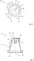
- the separation chamber 26 is connected near the top 18 to an inlet channel 44 (see Fig. 3 and 4 ).
- the inlet channel 44 preferably has a rectangular cross-section.
- An outer boundary wall 46 of the inlet channel 44 relative to the central axis 14 is formed in particular tangentially adjacent to a section 48 of the separating chamber wall 24, compare Fig.3 .
- a dip tube 50 is arranged on the top side 18 of the housing 12.
- the dip tube 50 extends along the central axis 14 into the separation chamber 26, see Fig.4
- a length 52 of the dip tube 50 taken up by the separation chamber 26 is measured parallel to the central axis 14.
- the expansion chamber 30 is connected to an outlet channel 54, wherein the outlet channel 54 preferably has a rectangular cross-section.
- An outer boundary wall 56 of the outlet channel 54 relative to the central axis 14 is formed in particular tangentially adjacent to a section 58 of the expansion chamber wall 32, see Fig.3 .
- a multiphase fluid is fed into the separation chamber 26 via the inlet channel 44, wherein the multiphase fluid is composed in particular of fluid phases of different densities (light fraction and heavy fraction).
- the multiphase fluid is guided along an inner side 60 of the separation chamber wall 24, whereby a flow is formed which extends spirally around the central axis 14 and has a flow component which points in the direction of the expansion chamber 30.
- the flow-related centrifugal forces cause a radially outward acceleration, in particular of the heavy fraction, and the separation of the heavy fraction on the inner side 60 of the separation chamber wall 24.
- the light fraction undergoes a flow reversal near the bottom side 22 and moves along the central axis 14 in the direction of the dip tube 50. 50 the light fraction is discharged from the separation chamber 26.
- a radially outward-directed centrifugal force 64 continues to act on the components 62 of the heavy fraction arranged on the inner side 60 of the separation chamber wall 24 after separation, compare Fig.5 .
- the centrifugal force 64 has a first component 66 and a second component 68.
- the first component 66 acts as a normal force on the components 62 of the heavy fraction and is aligned perpendicular to the inner side 60 of the separation chamber wall 24.
- the second component 68 of the centrifugal force 64 is aligned parallel to the inner side 60 of the separation chamber wall 24. Due to the conical expansion of the separation chamber 26 along the central axis 14, the second component 68 of the centrifugal force 64 is directed in the direction of the expansion chamber 30. This causes an acceleration of the components 62 of the heavy fraction in the direction of the expansion chamber 30 and an increased removal rate from the separation chamber 26 into the expansion chamber 30.
- the magnitude of the second component 68 of the centrifugal force 64 depends on the magnitude of the angle of inclination 36.
- a larger angle of inclination 36 measured relative to the central axis 14 is accompanied by a larger magnitude of the second component 68 of the centrifugal force 64.
- the rotation speed of the heavy fraction is slowed down by the enlarged diameter 42 of the expansion chamber 30, and the heavy fraction is discharged from the expansion chamber 30 via the outlet channel 54, compare e.g. Fig.1 .
- a bottom-side first fluid removal section 70 is provided which is spaced from the central axis 14 and has a screw thread-like gradient 72 relative to an orientation perpendicular to the central axis 14, see Fig.6 .
- An improvement in the removal of the heavy fraction can also be achieved with a bottom section 74 of the outlet channel 54, wherein the bottom section 74 has an outlet channel gradient 76 with respect to an orientation perpendicular to the central axis 14.
- a truncated cone-shaped fluid guide section 78 is provided, see Fig.7 , or a pagoda-shaped fluid guide section 80, compare Fig.8
- the fluid guide sections 78, 80 extend in a ring shape around the respective central axis 14.
- the upper sides of the fluid guide sections 78, 80 facing the separation chamber 26 or the expansion chamber 30 form inclined guide surfaces for guiding the components 62 of the heavy fraction radially outward, in particular in the direction of the outlet channel 54.
Landscapes
- Physics & Mathematics (AREA)
- Fluid Mechanics (AREA)
- Geometry (AREA)
- Centrifugal Separators (AREA)
Applications Claiming Priority (1)
| Application Number | Priority Date | Filing Date | Title |
|---|---|---|---|
| DE102022130081.1A DE102022130081A1 (de) | 2022-11-14 | 2022-11-14 | Fliehkraftabscheider |
Publications (3)
| Publication Number | Publication Date |
|---|---|
| EP4368295A1 true EP4368295A1 (fr) | 2024-05-15 |
| EP4368295B1 EP4368295B1 (fr) | 2025-06-04 |
| EP4368295C0 EP4368295C0 (fr) | 2025-06-04 |
Family
ID=88373957
Family Applications (1)
| Application Number | Title | Priority Date | Filing Date |
|---|---|---|---|
| EP23203123.7A Active EP4368295B1 (fr) | 2022-11-14 | 2023-10-12 | Séparateur centrifuge |
Country Status (4)
| Country | Link |
|---|---|
| US (1) | US20240157375A1 (fr) |
| EP (1) | EP4368295B1 (fr) |
| DE (1) | DE102022130081A1 (fr) |
| ES (1) | ES3036699T3 (fr) |
Citations (5)
| Publication number | Priority date | Publication date | Assignee | Title |
|---|---|---|---|---|
| US1798510A (en) * | 1924-09-25 | 1931-03-31 | Charles A Winslow | Air cleaner |
| US3996027A (en) * | 1974-10-31 | 1976-12-07 | Baxter Laboratories, Inc. | Swirling flow bubble trap |
| EP0676599A1 (fr) * | 1992-07-10 | 1995-10-11 | Aktsionernoe Obshestvo " SIGMA-GAZ" | Procede de refroidissement de gaz et refroidisseur de gaz |
| JP4978875B2 (ja) * | 2010-12-21 | 2012-07-18 | 有限会社吉工 | サイクロン |
| DE102017113888B3 (de) | 2017-06-22 | 2018-09-20 | Sebastian Porkert | Fliehkraftabscheider |
Family Cites Families (3)
| Publication number | Priority date | Publication date | Assignee | Title |
|---|---|---|---|---|
| GB1185274A (en) * | 1967-06-13 | 1970-03-25 | Grubbens And Company Aktiebola | Cyclone Separator |
| US3558484A (en) * | 1969-12-11 | 1971-01-26 | Wayne F Carr | Separating apparatus |
| SE412529B (sv) * | 1977-03-07 | 1980-03-10 | Celleco Ab | Anordning vid en hydrocyklonseparator for att minska risken for forlust av lett fraktion och igensettning av den tunga fraktionens utloppsoppning |
-
2022
- 2022-11-14 DE DE102022130081.1A patent/DE102022130081A1/de not_active Ceased
-
2023
- 2023-10-12 ES ES23203123T patent/ES3036699T3/es active Active
- 2023-10-12 EP EP23203123.7A patent/EP4368295B1/fr active Active
- 2023-11-07 US US18/503,428 patent/US20240157375A1/en active Pending
Patent Citations (5)
| Publication number | Priority date | Publication date | Assignee | Title |
|---|---|---|---|---|
| US1798510A (en) * | 1924-09-25 | 1931-03-31 | Charles A Winslow | Air cleaner |
| US3996027A (en) * | 1974-10-31 | 1976-12-07 | Baxter Laboratories, Inc. | Swirling flow bubble trap |
| EP0676599A1 (fr) * | 1992-07-10 | 1995-10-11 | Aktsionernoe Obshestvo " SIGMA-GAZ" | Procede de refroidissement de gaz et refroidisseur de gaz |
| JP4978875B2 (ja) * | 2010-12-21 | 2012-07-18 | 有限会社吉工 | サイクロン |
| DE102017113888B3 (de) | 2017-06-22 | 2018-09-20 | Sebastian Porkert | Fliehkraftabscheider |
Also Published As
| Publication number | Publication date |
|---|---|
| ES3036699T3 (en) | 2025-09-23 |
| US20240157375A1 (en) | 2024-05-16 |
| EP4368295B1 (fr) | 2025-06-04 |
| EP4368295C0 (fr) | 2025-06-04 |
| DE102022130081A1 (de) | 2024-05-16 |
Similar Documents
| Publication | Publication Date | Title |
|---|---|---|
| DE69129151T2 (de) | Hochleistungsfähiger flüssigkeit/flüssigkeit-hydrozyklon | |
| DE69328817T2 (de) | Dekantierzentrifuge zur hochgradigen Eindickung | |
| EP0207927B1 (fr) | Dispositif pour la séparation de la poussière des gaz | |
| DE69228252T2 (de) | Zufuhrbeschleunigungssystem mit beschleunigungskegel | |
| EP3132856B1 (fr) | Hydrocyclone à appauvrissement en matières fines dans le tamisat inférieur du cyclone | |
| DE4012384A1 (de) | Zyklonabscheider zum trennen von schmutzteilchen aus fluiden | |
| EP3661653B1 (fr) | Cyclone dépoussiéreur à courant continu | |
| EP2902112B1 (fr) | Dispositif d'évacuation et centrifugeuse à vis a bol plein | |
| EP2624960B1 (fr) | Dispositif de séparation avec séparateur cyclonique | |
| DE3624086C2 (fr) | ||
| EP4368295B1 (fr) | Séparateur centrifuge | |
| DE2443487A1 (de) | Magnetscheidersystem | |
| DE3787656T2 (de) | Hydrozyklone. | |
| DE68913882T2 (de) | Wirbelrohr-Abscheider. | |
| EP1820604B1 (fr) | Tête de buse | |
| DE102022104631B4 (de) | Gleichstromzyklonabscheider | |
| DE69307486T2 (de) | Verfahren und Vorrichtung zur Phasentrennung | |
| AT517209B1 (de) | Zyklonabscheider | |
| DE3238361C2 (fr) | ||
| DE2046642C3 (de) | Abscheider für einen Zentrifugalapparat mit freier Wirbelströmung | |
| DE10121434B4 (de) | Vollmantel-Schneckenzentrifuge | |
| DE10230881A1 (de) | Wasserabscheider für Klimaanlagen | |
| EP3184176B1 (fr) | Dispositif de conduite d'un dispositif de separation | |
| EP2711082A2 (fr) | Hydrocyclone | |
| DE2339435A1 (de) | Verfahren und vorrichtung zum abscheiden von teilchen aus einem stroemungsmedium |
Legal Events
| Date | Code | Title | Description |
|---|---|---|---|
| PUAI | Public reference made under article 153(3) epc to a published international application that has entered the european phase |
Free format text: ORIGINAL CODE: 0009012 |
|
| STAA | Information on the status of an ep patent application or granted ep patent |
Free format text: STATUS: THE APPLICATION HAS BEEN PUBLISHED |
|
| AK | Designated contracting states |
Kind code of ref document: A1 Designated state(s): AL AT BE BG CH CY CZ DE DK EE ES FI FR GB GR HR HU IE IS IT LI LT LU LV MC ME MK MT NL NO PL PT RO RS SE SI SK SM TR |
|
| STAA | Information on the status of an ep patent application or granted ep patent |
Free format text: STATUS: REQUEST FOR EXAMINATION WAS MADE |
|
| 17P | Request for examination filed |
Effective date: 20241113 |
|
| RBV | Designated contracting states (corrected) |
Designated state(s): AL AT BE BG CH CY CZ DE DK EE ES FI FR GB GR HR HU IE IS IT LI LT LU LV MC ME MK MT NL NO PL PT RO RS SE SI SK SM TR |
|
| GRAP | Despatch of communication of intention to grant a patent |
Free format text: ORIGINAL CODE: EPIDOSNIGR1 |
|
| STAA | Information on the status of an ep patent application or granted ep patent |
Free format text: STATUS: GRANT OF PATENT IS INTENDED |
|
| GRAS | Grant fee paid |
Free format text: ORIGINAL CODE: EPIDOSNIGR3 |
|
| INTG | Intention to grant announced |
Effective date: 20250328 |
|
| GRAA | (expected) grant |
Free format text: ORIGINAL CODE: 0009210 |
|
| STAA | Information on the status of an ep patent application or granted ep patent |
Free format text: STATUS: THE PATENT HAS BEEN GRANTED |
|
| AK | Designated contracting states |
Kind code of ref document: B1 Designated state(s): AL AT BE BG CH CY CZ DE DK EE ES FI FR GB GR HR HU IE IS IT LI LT LU LV MC ME MK MT NL NO PL PT RO RS SE SI SK SM TR |
|
| REG | Reference to a national code |
Ref country code: GB Ref legal event code: FG4D Free format text: NOT ENGLISH |
|
| REG | Reference to a national code |
Ref country code: CH Ref legal event code: EP |
|
| REG | Reference to a national code |
Ref country code: DE Ref legal event code: R096 Ref document number: 502023001090 Country of ref document: DE |
|
| REG | Reference to a national code |
Ref country code: IE Ref legal event code: FG4D Free format text: LANGUAGE OF EP DOCUMENT: GERMAN |
|
| U01 | Request for unitary effect filed |
Effective date: 20250626 |
|
| U07 | Unitary effect registered |
Designated state(s): AT BE BG DE DK EE FI FR IT LT LU LV MT NL PT RO SE SI Effective date: 20250702 |
|
| REG | Reference to a national code |
Ref country code: ES Ref legal event code: FG2A Ref document number: 3036699 Country of ref document: ES Kind code of ref document: T3 Effective date: 20250923 |
|
| PG25 | Lapsed in a contracting state [announced via postgrant information from national office to epo] |
Ref country code: NO Free format text: LAPSE BECAUSE OF FAILURE TO SUBMIT A TRANSLATION OF THE DESCRIPTION OR TO PAY THE FEE WITHIN THE PRESCRIBED TIME-LIMIT Effective date: 20250904 Ref country code: GR Free format text: LAPSE BECAUSE OF FAILURE TO SUBMIT A TRANSLATION OF THE DESCRIPTION OR TO PAY THE FEE WITHIN THE PRESCRIBED TIME-LIMIT Effective date: 20250905 |
|
| PG25 | Lapsed in a contracting state [announced via postgrant information from national office to epo] |
Ref country code: PL Free format text: LAPSE BECAUSE OF FAILURE TO SUBMIT A TRANSLATION OF THE DESCRIPTION OR TO PAY THE FEE WITHIN THE PRESCRIBED TIME-LIMIT Effective date: 20250604 |
|
| PG25 | Lapsed in a contracting state [announced via postgrant information from national office to epo] |
Ref country code: HR Free format text: LAPSE BECAUSE OF FAILURE TO SUBMIT A TRANSLATION OF THE DESCRIPTION OR TO PAY THE FEE WITHIN THE PRESCRIBED TIME-LIMIT Effective date: 20250604 |
|
| PG25 | Lapsed in a contracting state [announced via postgrant information from national office to epo] |
Ref country code: RS Free format text: LAPSE BECAUSE OF FAILURE TO SUBMIT A TRANSLATION OF THE DESCRIPTION OR TO PAY THE FEE WITHIN THE PRESCRIBED TIME-LIMIT Effective date: 20250904 |
|
| RAP4 | Party data changed (patent owner data changed or rights of a patent transferred) |
Owner name: SYNTEGON TECHNOLOGY GMBH |
|
| U1H | Name or address of the proprietor changed after the registration of the unitary effect |
Owner name: SYNTEGON TECHNOLOGY GMBH; DE |
|
| U20 | Renewal fee for the european patent with unitary effect paid |
Year of fee payment: 3 Effective date: 20251027 |
|
| PG25 | Lapsed in a contracting state [announced via postgrant information from national office to epo] |
Ref country code: IS Free format text: LAPSE BECAUSE OF FAILURE TO SUBMIT A TRANSLATION OF THE DESCRIPTION OR TO PAY THE FEE WITHIN THE PRESCRIBED TIME-LIMIT Effective date: 20251004 |
|
| PG25 | Lapsed in a contracting state [announced via postgrant information from national office to epo] |
Ref country code: SM Free format text: LAPSE BECAUSE OF FAILURE TO SUBMIT A TRANSLATION OF THE DESCRIPTION OR TO PAY THE FEE WITHIN THE PRESCRIBED TIME-LIMIT Effective date: 20250604 |
|
| PG25 | Lapsed in a contracting state [announced via postgrant information from national office to epo] |
Ref country code: CZ Free format text: LAPSE BECAUSE OF FAILURE TO SUBMIT A TRANSLATION OF THE DESCRIPTION OR TO PAY THE FEE WITHIN THE PRESCRIBED TIME-LIMIT Effective date: 20250604 |
|
| PGFP | Annual fee paid to national office [announced via postgrant information from national office to epo] |
Ref country code: IE Payment date: 20251021 Year of fee payment: 3 |
|
| PG25 | Lapsed in a contracting state [announced via postgrant information from national office to epo] |
Ref country code: SK Free format text: LAPSE BECAUSE OF FAILURE TO SUBMIT A TRANSLATION OF THE DESCRIPTION OR TO PAY THE FEE WITHIN THE PRESCRIBED TIME-LIMIT Effective date: 20250604 |
|
| PGFP | Annual fee paid to national office [announced via postgrant information from national office to epo] |
Ref country code: ES Payment date: 20251114 Year of fee payment: 3 |
|
| REG | Reference to a national code |
Ref country code: CH Ref legal event code: R18 Free format text: ST27 STATUS EVENT CODE: U-0-0-R10-R18 (AS PROVIDED BY THE NATIONAL OFFICE) Effective date: 20260213 |
|
| PLBE | No opposition filed within time limit |
Free format text: ORIGINAL CODE: 0009261 |
|
| STAA | Information on the status of an ep patent application or granted ep patent |
Free format text: STATUS: NO OPPOSITION FILED WITHIN TIME LIMIT |
|
| REG | Reference to a national code |
Ref country code: CH Ref legal event code: L10 Free format text: ST27 STATUS EVENT CODE: U-0-0-L10-L00 (AS PROVIDED BY THE NATIONAL OFFICE) Effective date: 20260416 |