EP4368366A1 - Dispositif d'emboutissage profond, machine d'emballage dotée d'un dispositif d'emboutissage profond et procédé de fonctionnement du dispositif d'emboutissage profond - Google Patents
Dispositif d'emboutissage profond, machine d'emballage dotée d'un dispositif d'emboutissage profond et procédé de fonctionnement du dispositif d'emboutissage profond Download PDFInfo
- Publication number
- EP4368366A1 EP4368366A1 EP22206800.9A EP22206800A EP4368366A1 EP 4368366 A1 EP4368366 A1 EP 4368366A1 EP 22206800 A EP22206800 A EP 22206800A EP 4368366 A1 EP4368366 A1 EP 4368366A1
- Authority
- EP
- European Patent Office
- Prior art keywords
- film
- deep
- clamping
- contour
- drawing device
- Prior art date
- Legal status (The legal status is an assumption and is not a legal conclusion. Google has not performed a legal analysis and makes no representation as to the accuracy of the status listed.)
- Granted
Links
Images

Classifications
-
- B—PERFORMING OPERATIONS; TRANSPORTING
- B29—WORKING OF PLASTICS; WORKING OF SUBSTANCES IN A PLASTIC STATE IN GENERAL
- B29C—SHAPING OR JOINING OF PLASTICS; SHAPING OF MATERIAL IN A PLASTIC STATE, NOT OTHERWISE PROVIDED FOR; AFTER-TREATMENT OF THE SHAPED PRODUCTS, e.g. REPAIRING
- B29C51/00—Shaping by thermoforming, i.e. shaping sheets or sheet like preforms after heating, e.g. shaping sheets in matched moulds or by deep-drawing; Apparatus therefor
- B29C51/26—Component parts, details or accessories; Auxiliary operations
- B29C51/261—Handling means, e.g. transfer means, feeding means
- B29C51/262—Clamping means for the sheets, e.g. clamping frames
-
- B—PERFORMING OPERATIONS; TRANSPORTING
- B29—WORKING OF PLASTICS; WORKING OF SUBSTANCES IN A PLASTIC STATE IN GENERAL
- B29C—SHAPING OR JOINING OF PLASTICS; SHAPING OF MATERIAL IN A PLASTIC STATE, NOT OTHERWISE PROVIDED FOR; AFTER-TREATMENT OF THE SHAPED PRODUCTS, e.g. REPAIRING
- B29C51/00—Shaping by thermoforming, i.e. shaping sheets or sheet like preforms after heating, e.g. shaping sheets in matched moulds or by deep-drawing; Apparatus therefor
- B29C51/04—Combined thermoforming and prestretching, e.g. biaxial stretching
- B29C51/06—Combined thermoforming and prestretching, e.g. biaxial stretching using pressure difference for prestretching
-
- B—PERFORMING OPERATIONS; TRANSPORTING
- B29—WORKING OF PLASTICS; WORKING OF SUBSTANCES IN A PLASTIC STATE IN GENERAL
- B29C—SHAPING OR JOINING OF PLASTICS; SHAPING OF MATERIAL IN A PLASTIC STATE, NOT OTHERWISE PROVIDED FOR; AFTER-TREATMENT OF THE SHAPED PRODUCTS, e.g. REPAIRING
- B29C51/00—Shaping by thermoforming, i.e. shaping sheets or sheet like preforms after heating, e.g. shaping sheets in matched moulds or by deep-drawing; Apparatus therefor
- B29C51/26—Component parts, details or accessories; Auxiliary operations
- B29C51/30—Moulds
- B29C51/36—Moulds specially adapted for vacuum forming, Manufacture thereof
-
- B—PERFORMING OPERATIONS; TRANSPORTING
- B29—WORKING OF PLASTICS; WORKING OF SUBSTANCES IN A PLASTIC STATE IN GENERAL
- B29C—SHAPING OR JOINING OF PLASTICS; SHAPING OF MATERIAL IN A PLASTIC STATE, NOT OTHERWISE PROVIDED FOR; AFTER-TREATMENT OF THE SHAPED PRODUCTS, e.g. REPAIRING
- B29C2791/00—Shaping characteristics in general
- B29C2791/004—Shaping under special conditions
- B29C2791/006—Using vacuum
-
- B—PERFORMING OPERATIONS; TRANSPORTING
- B29—WORKING OF PLASTICS; WORKING OF SUBSTANCES IN A PLASTIC STATE IN GENERAL
- B29C—SHAPING OR JOINING OF PLASTICS; SHAPING OF MATERIAL IN A PLASTIC STATE, NOT OTHERWISE PROVIDED FOR; AFTER-TREATMENT OF THE SHAPED PRODUCTS, e.g. REPAIRING
- B29C51/00—Shaping by thermoforming, i.e. shaping sheets or sheet like preforms after heating, e.g. shaping sheets in matched moulds or by deep-drawing; Apparatus therefor
- B29C51/10—Forming by pressure difference, e.g. vacuum
-
- B—PERFORMING OPERATIONS; TRANSPORTING
- B29—WORKING OF PLASTICS; WORKING OF SUBSTANCES IN A PLASTIC STATE IN GENERAL
- B29C—SHAPING OR JOINING OF PLASTICS; SHAPING OF MATERIAL IN A PLASTIC STATE, NOT OTHERWISE PROVIDED FOR; AFTER-TREATMENT OF THE SHAPED PRODUCTS, e.g. REPAIRING
- B29C51/00—Shaping by thermoforming, i.e. shaping sheets or sheet like preforms after heating, e.g. shaping sheets in matched moulds or by deep-drawing; Apparatus therefor
- B29C51/26—Component parts, details or accessories; Auxiliary operations
- B29C51/266—Auxiliary operations after the thermoforming operation
-
- B—PERFORMING OPERATIONS; TRANSPORTING
- B29—WORKING OF PLASTICS; WORKING OF SUBSTANCES IN A PLASTIC STATE IN GENERAL
- B29C—SHAPING OR JOINING OF PLASTICS; SHAPING OF MATERIAL IN A PLASTIC STATE, NOT OTHERWISE PROVIDED FOR; AFTER-TREATMENT OF THE SHAPED PRODUCTS, e.g. REPAIRING
- B29C51/00—Shaping by thermoforming, i.e. shaping sheets or sheet like preforms after heating, e.g. shaping sheets in matched moulds or by deep-drawing; Apparatus therefor
- B29C51/26—Component parts, details or accessories; Auxiliary operations
- B29C51/42—Heating or cooling
- B29C51/421—Heating or cooling of preforms, specially adapted for thermoforming
-
- B—PERFORMING OPERATIONS; TRANSPORTING
- B29—WORKING OF PLASTICS; WORKING OF SUBSTANCES IN A PLASTIC STATE IN GENERAL
- B29L—INDEXING SCHEME ASSOCIATED WITH SUBCLASS B29C, RELATING TO PARTICULAR ARTICLES
- B29L2031/00—Other particular articles
- B29L2031/712—Containers; Packaging elements or accessories, Packages
- B29L2031/7174—Capsules
Definitions
- the invention relates to a deep-drawing device with the features according to the preamble of claim 1 and a packaging machine for producing filled bags with such a deep-drawing device as well as a method for operating the deep-drawing device.
- packaging units are often produced by first deep-drawing films. A product is filled into the cavities created, which are then sealed with a cover film. This creates a double-layered film strip in which partial quantities of the product are separated from one another. These partial quantities are then separated in a cutting station.
- the film of the packaging unit can withstand external stresses so that the packaged product is adequately protected. If it was discovered during the manufacturing process of packaging units that the film had torn or had partially thinned out to such an extent that the film was leaking, the countermeasures used to be to increase the film thickness.
- the molding process parameters such as the preheating temperature or preheating time of the film, can also be adjusted. This can prevent defects in the film packaging. However, the use of a thicker film can lead to increased environmental impact. In addition, the necessary adjustments also result in increased production costs.
- thermoforming device which enables a process-reliable, environmentally friendly and at the same time cost-effective production of filled film bags.
- a further object of the invention is to provide a packaging machine which enables a process-reliable, environmentally friendly and at the same time cost-effective production of filled film bags.
- a further object of the invention is to provide a method for deep-drawing film for the production of film packaging, which enables a process-reliable, environmentally friendly and at the same time inexpensive production of filled film bags.
- the invention is based on the finding that the irregular dissolution times of the water-soluble films are at least largely due to an uneven film thickness. It was also found that the uneven film thickness arises during the deep-drawing of the film.
- One factor influencing increased thinning of the film is the size of the film section provided for deep-drawing. It is known from the prior art that the film is held clamped on the die plate via a heating plate. The heating plate has a flat underside for this purpose. The heating plate is lowered and comes to rest flat on the film. The clamping surface resulting between the heating plate and the die plate encloses each individual cavity, which limits the material flow of the film during deep-drawing.
- the deep-drawing device comprises an arrangement of several die plates which can be driven by a conveyor in a circulating path, each die plate comprising at least two individual cavities on an upper side, and with at least one Mold vacuum device, wherein the mold vacuum device comprises at least one first vacuum source for providing a vacuum, and wherein the at least one first vacuum source can be connected via a first vacuum channel to the at least two individual cavities of each die plate for providing a vacuum for deep-drawing a film, and to at least one heating plate for heating the film, wherein the heating plate comprises on its underside a clamping device with at least one clamping means for clamping the film, wherein the clamping means has a clamping contour for contacting the film, and wherein the clamping contour at least partially runs around at least two individual cavities in a position of the deep-drawing device in which the film is clamped in the direction of view perpendicular to the top of the die plate.
- the clamping contour assigns a larger, common film section to the at least two individual cavities of the die plate. This means that the material requirement during deep drawing is leveled out depending on the geometric design of the individual cavities.
- the at least two individual cavities namely a first individual cavity and a second individual cavity, are preferably arranged adjacent to one another. If, for example, the first individual cavity has an increased depth in one area, a corresponding amount of film material must be provided for this area. If the second individual cavity has a section adjacent to this area of the first individual cavity in which the depth of the second individual cavity is reduced, more film material will flow to the area of the first individual cavity than to the section of the second individual cavity. This results in a material balance between the two individual cavities, since they are not separated from one another by a clamping contour. The film can flow freely between the at least two individual cavities.
- the film undergoes a more uniform thinning.
- the use of a film with increased film thickness to avoid material failure is no longer necessary.
- the packaging units can be produced in an environmentally friendly and cost-effective manner.
- the dissolution time of the films, especially the PVOH films, in the water can also be adjusted in a process-safe and reproducible manner.
- the clamping contour completely surrounds at least two individual cavities when the deep-drawing device is in a position in which the film is clamped, looking perpendicularly at the top of the die plate. This increases the clamping effect of the clamping device on the film.
- the clamping device is designed such that in the clamped position of the deep-drawing device the film is clamped directly between the clamping contour of the clamping means and the top of the die plate.
- the clamping means is particularly preferably designed as a clamping web. It is advantageously provided that the clamping web forms the only clamping means of the clamping device and, in a position of the deep-drawing device in which the film is clamped, runs around all the individual cavities of the die plate in a direction perpendicular to the top of the die plate. All the individual cavities are therefore not separated from one another by a clamping contour. Consequently, the film can flow freely between all the individual cavities. In such a design of the clamping device, the clamping web forms a clamping frame that encloses the individual cavities.
- the clamping contour of the clamping means is formed directly on the underside of the heating plate.
- the clamping device is preferably formed in one piece with the heating plate. In an alternative embodiment, however, it may also be expedient to form the clamping device separately from the heating plate. In such an embodiment, preferably only the clamping device on the heating plate would be replaceable.
- the clamping contour of the clamping means encloses a shape contour of the heating plate, wherein the shape contour is designed as a recess on the underside of the heating plate opposite the clamping contour.
- the shape contour is designed to be spaced apart from the film in the clamped position of the deep-drawing device.
- the shape contour of the heating plate is preferably milled.
- At least one capillary opening is formed on the shape contour of the heating plate, wherein the at least one capillary opening is connected to a first vacuum source and/or a second vacuum source via a second vacuum channel.
- the capillary opening is preferably designed as a capillary bore. If a vacuum is applied to the shape contour, the film is sucked onto the shape contour of the heating plate and thereby pre-stretched. Particularly preferably, several capillary openings are provided in the shape contour.
- the film is heated by the heating plate. This promotes the flow behavior of the film. It is advantageous that a vacuum is applied to the mold contour of the heating plate to pre-stretch the film, whereby the film is sucked into the heating plate and adheres to the mold contour. The film is thereby pre-stretched.
- the film in particular after pre-stretching, is deep-drawn into the die mold of the die plate by a vacuum applied to the die mold.
- a vacuum is applied to the die mold, the vacuum in the mold contour is preferably deactivated at the same time. This means that the deep-drawing force acting on the film, which is generated by the vacuum applied to the die mold, is not counteracted by a force generated by the vacuum on the mold contour.
- it can advantageously be provided to apply an overpressure to the mold contour, so that the film is additionally pressed into the die mold by a pressure force acting on the film by the overpressure.
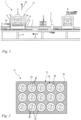
- Fig.1 shows a side view of a section of a packaging machine 1 according to the invention for producing filled bags.
- the packaging machine 1 comprises a machine frame 8, a forming station 4, a filling station 5 and a sealing station 6.
- a film 2 is fed to the packaging machine 1 and deep-drawn in the forming station 4 so that cavities are formed in the film 2.
- the film 2 is designed as a film web. It can also be expedient to feed individual film sheets to the packaging machine 1.
- the cavities are filled with a product in the filling station 5.
- a cover film 3 is then fed in and sealed onto the film web 2 in the sealing station 6, whereby the filled cavities are closed.
- the film unit formed in this way is separated into film bags.
- the film 2 and the cover film 3 are water-soluble films, namely PVOH films, between which, for example, a washing or cleaning agent is packaged. Filled film bags produced in this way are placed in a dishwasher, for example. There, the film material dissolves on contact with water and releases the detergent contained therein. The same applies analogously to the use of such a film bag in a washing machine.
- the packaging machine 1 comprises the stationary machine frame 8 and a preferably continuously driven conveyor 7.
- the conveyor 7 can be a conveyor belt or the like and in the preferred embodiment is formed by elements that are connected to one another in an articulated and chain-like manner and on which several die plates 9, 9' are mounted.
- the latter are preferably driven continuously and in rotation around the machine frame 8 together with the conveyor 7, whereby they move on an upper horizontal track according to an arrow 30 for the actual production process of the bags and, after appropriate deflection, are then returned in the lower area of the machine frame 8 according to an arrow 31.
- the film 2, a preferably endless film web is also preferably fed continuously and placed from above on the conveyor 7 with the die plates 9, 9'.
- the cover film 3 is later preferably fed continuously between the filling station 5 and the sealing station 6 and placed from above on the top of the film 2. When applied, the film 2 and the cover film 3 are moved synchronously and preferably continuously with the conveyor 7 according to the arrow 30.
- the station for feeding the film 2 and the station for feeding the cover film 3 are stationary relative to the machine frame 8, as are stations (not shown) for applying water to support the sealing process and for perforating or laterally trimming the films. It can also be provided that the stations are at least partially attached to the machine frame.
- the movement of the conveyor 7 is continuous. In such an embodiment of the packaging machine 1, the processes carried out here also work continuously.
- the forming station 4, the filling station 5 and the sealing station 6 are not positioned stationary relative to the machine frame 8, but are moved in sections over a certain distance synchronously with the conveyor 7.
- the film 2 is deep-drawn in the forming station 4, the product to be packaged is filled into the deep-drawn cavities in the filling station 5, and the cover film 3 is sealed onto the lower film 2 in the sealing station 6.
- the forming station 4, the filling station 5, and the sealing station 6 are cyclically moved back to their starting position, where a new cycle of the respective process begins.
- the forming station 4 is formed by a deep-drawing device 12.
- the deep-drawing device 12 can be designed to accommodate only a single die plate 9, 9' and to deep-draw the film 2 there in one cycle. In the embodiment shown, the deep-drawing device 12 is designed to simultaneously accommodate several, here two consecutive die plates 9, 9'.
- a single die plate 9, 9' has at least two individual cavities 36 on its upper side 43.
- the at least two individual cavities 36 can form a single die mold 10 or two die molds.
- four individual cavities 36 are formed on each die plate 9, 9'.
- 44 or 48 products are formed on a die plate 9, 9', each product in turn being formed from one or more individual cavities 36.
- Each individual cavity 36 is provided with at least one capillary bore 11, preferably several capillary bores 11.
- the capillary bores 11 are part of a first vacuum channel 26, via which the individual cavities 36 are connected to a first vacuum source 21.
- the capillary bores 11 of an individual cavity 36 open into a common vacuum chamber 29, as a result of which the capillary bores 11 are fluidly connected to one another. Pressure equalization thus takes place between the individual capillary bores 11 via the vacuum chamber 29.
- the vacuum chamber 29 is preferably formed on an underside 44 of the die plate 9, 9'.
- the underside 44 of the die plate 9, 9' is the side of the die plate 9, 9' facing away from the top side 43 of the die plate 9, 9'.
- the vacuum chamber 29 is also part of the first vacuum channel 26.
- the first vacuum source 21 generates a vacuum, i.e.
- the vacuum can be switched on to the individual cavities 36 via a valve (not shown in detail) that is functionally arranged in the first vacuum channel 26 between the vacuum source 21 and the die mold 10.
- a valve (not shown in detail) that is functionally arranged in the first vacuum channel 26 between the vacuum source 21 and the die mold 10.
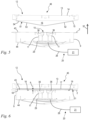
- the deep-drawing device 12 comprises a heating plate 13.
- the heating plate 13 serves to heat the film 2 before and/or during deep-drawing. This promotes the material flow of the film.
- the die plate 9, 9' with the film 2 arranged on it is positioned below the heating plate 13.
- the heating plate 13 is then lowered until a distance a is set between the heating plate 13 and the film 2. The closer the heating plate 13 is positioned to the film 2, the higher the heat transfer to the Film 2.
- the distance a can be chosen to be larger or smaller depending on the required flow behavior of the film 2, whereby the global heat transfer from the heating plate 13 to the film 2 can be adjusted.
- the heating plate 13 is moved up and down in the vertical direction 32 via a pressure plate 34.
- the vertical direction 32 runs from a bottom side 15 of the heating plate 13 to a top side 14 of the heating plate 13.
- the vertical direction 32 is preferably opposite to the direction of gravity.
- the heating plate 13 comprises the upper side 14 facing away from the die plate 9, 9' and the lower side 15 facing the die plate 9, 9'.
- the heating plate 13 comprises a clamping device 51 on its lower side 15.
- the clamping device 51 in the present embodiment comprises only a clamping means 52 with a clamping contour 53.
- the clamping means 52 is designed as a clamping web 54.
- the clamping web 54 runs adjacent to the long sides and the transverse sides of the heating plate 13.
- the clamping web 54 thus forms a substantially rectangular clamping contour 53.
- the clamping web 54 forms in the embodiment according to the Figures 4 to 6 a kind of clamping frame.
- the heating plate 13 comprises at least one shape contour 16.
- the clamping contour 53 of the clamping means 52 runs around the shape contour 16.
- the heating plate 13 comprises only a single shape contour 16.
- the shape contour 16 is formed from a flat surface.
- the shape contour 16 is designed as a recess 19 opposite the clamping means 52. Accordingly, with respect to the vertical direction 32, the clamping contour 53 of the clamping means 52 lies below the shape contour 16.
- the Fig.6 shows the deep-drawing device 12 in a position 45 in which the film 2 is clamped.
- the heating plate 13 contacts the film 2 with the clamping contour 53 of the clamping means 52.
- the film 2 is clamped over the clamping contour 53 of the Clamping means 52 is pressed against the top side 43 of the die plate 9, 9' and is thereby held clamped.
- the heating plate 13 is contact-free with the film 2.
- the distance between the mold contour 16 of the heating plate 13 and the film 2 is therefore always greater than zero.
- the clamping contour 53 runs around the individual cavities 36 of the die plate 9, 9'.
- the clamping contour 53 only partially runs around the individual cavities 36.
- the preferred embodiment of the heating plate 13, however, is designed such that the clamping contour 53 runs completely around the individual cavities 36.
- a clamping device 51 is shown, which in essence of the clamping device 51 according to the Figures 4 to 6 corresponds.
- the cut surface of the clamping means 52 which presses the film 2 against the upper side 43 of the die plate 9, 9', is shown hatched.
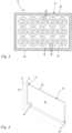
- 30 individual cavities 36 are formed on the die plate 9, 9', all of which are completely surrounded by the clamping contour 53 of the clamping means 52.
- the individual cavities 36 are not separated from one another by further clamping contours.
- the film 2 can therefore flow freely between the individual cavities 36. The material flow of the film 2 is thus promoted, whereby an equalization of the film thickness can be achieved.
- the film 2 is deep-drawn into the individual cavities 36.
- a vacuum is created in the individual cavities 36.
- the film 2 can flow freely between the individual cavities 36, whereby a locally increased thinning of the film 2 can be avoided.
- the shape contour 16 is preferably milled into the heating plate 13.
- adapted heating plates 13 must be produced. If the die plates 9, 9' of a packaging machine 1 is changed, the heating plate 13 of the deep-drawing device 12 must also be replaced.
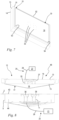
- the Figures 7 to 9 show a particularly preferred embodiment of the deep-drawing device 12 according to the invention, which differs from the embodiment according to the Figures 4 to 6 only differs in that the heating plate 13 enables pre-stretching of the film 2.
- at least one capillary opening 35 is provided on the mold contour 16 of the heating plate 13.
- the at least one capillary opening 35 is connected to a second vacuum source 27 via a second vacuum channel 28.
- the second vacuum channel 28 is connected to the first vacuum source 21 or to both the first vacuum source 21 and the second vacuum source 27.
- the vacuum sources 21, 27 and the corresponding vacuum channels 27, 28 are only shown schematically in all figures.
- the second vacuum source 27 and the second vacuum channel 28 are also part of a mold vacuum device 20.
- capillary openings 35 are provided on the mold contour 16.
- the capillary openings 35 are preferably designed as bores.
- the capillary openings 35 open into a second vacuum chamber 37, via which the capillary openings 35 are fluidly connected to one another. Accordingly, pressure equalization between the capillary openings 35 of the mold contour 16 takes place via the second vacuum chamber 37.
- the second vacuum chamber 37 like the capillary openings 35 of the mold contour 16, is part of the second vacuum channel 28.
- a vacuum is applied to the mold contour 16 via the second and/or first vacuum source 21, 27, whereby a film section 17 of the film 2 is sucked onto the mold contour 16.
- the film 2 comes into contact with the mold contour 16 in particular in the area of the capillary openings 35. In these areas, the film 2 directly contacts the heating plate 13, which increases the heat transfer to the film 2.
- the capillary openings 35 are preferably distributed in the mold contour 16 in such a way that the film comes into contact with the heating plate 13 in those areas where the flow behavior of the film 2 is to be promoted.
- the same also applies to the pre-stretching of the film 2.
- the areas that are to have increased flow behavior are to be pre-stretched using the negative pressure of the capillary bores 35.
- the capillary openings 35 are to be distributed accordingly over the mold contour 16.
- the negative pressure on the mold contour 16 is deactivated and at the same time the negative pressure in the die mold 10 is switched on.
- the film 2 is deep-drawn.
- an overpressure can also be applied to the mold contour 16 in order to promote the deep-drawing of the film 2.
- a new die plate 9, 9' is then assigned to the deep-drawing device 12 and the deep-drawing process is repeated again.
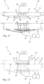
- a further embodiment of the deep-drawing device 12 is shown, which differs from the embodiment according to the Figures 7 to 9 only differs in the design of the clamping device 51.
- the clamping device 51 is formed by a clamping surface 55, wherein the clamping contour 53 is formed by a clamping edge 56 adjacent to the shape contour 16.
- the shape contour 16 is formed as a recess 19 opposite the clamping surface 55.
- the clamping means 52 is formed by a continuous shape contour 53. As in the embodiment according to the Figures 10 to 12 shown, the clamping contour 53 runs around at least four individual cavities 36.
- the clamping device 51 contacts the film 2 with its clamping surface 55.
- the mold contour 16 is not in contact with the film 2. Only when the vacuum is activated on the mold contour 16 to pre-stretch the film 2 is the film 2 applied to the mold contour 16. Since the vacuum on the mold contour 16 is deactivated during deep drawing, the film 2 can of course flow freely between the individual cavities 36.
- Fig.2 is a schematic sectional view of an embodiment of a clamping device 51 in the direction of view of the upper side 43 of the matrix plate 9, 9', which in essence is designed according to the Figures 10 to 12 corresponds.
- the clamping device 51 designed as a clamping surface 55 has a plurality of clamping means 52, the clamping contour of which each runs around two individual cavities 36. This allows the film 2 to flow freely between two individual cavities during deep drawing. The material flow of the film 2 is thus promoted during deep drawing.
Landscapes
- Engineering & Computer Science (AREA)
- Mechanical Engineering (AREA)
- Manufacturing & Machinery (AREA)
- Blow-Moulding Or Thermoforming Of Plastics Or The Like (AREA)
- Moulds For Moulding Plastics Or The Like (AREA)
Priority Applications (3)
| Application Number | Priority Date | Filing Date | Title |
|---|---|---|---|
| EP22206800.9A EP4368366B1 (fr) | 2022-11-10 | 2022-11-10 | Dispositif d'emboutissage profond, machine d'emballage dotée d'un dispositif d'emboutissage profond et procédé de fonctionnement du dispositif d'emboutissage profond |
| ES22206800T ES3048134T3 (en) | 2022-11-10 | 2022-11-10 | Deep drawing device, packaging machine with a deep drawing device and method for operating the deep drawing device |
| PL22206800.9T PL4368366T3 (pl) | 2022-11-10 | 2022-11-10 | Urządzenie do formowania wgłębnego, maszyna pakująca z urządzeniem do formowania wgłębnego i sposób eksploatacji urządzenia do formowania wgłębnego |
Applications Claiming Priority (1)
| Application Number | Priority Date | Filing Date | Title |
|---|---|---|---|
| EP22206800.9A EP4368366B1 (fr) | 2022-11-10 | 2022-11-10 | Dispositif d'emboutissage profond, machine d'emballage dotée d'un dispositif d'emboutissage profond et procédé de fonctionnement du dispositif d'emboutissage profond |
Publications (2)
| Publication Number | Publication Date |
|---|---|
| EP4368366A1 true EP4368366A1 (fr) | 2024-05-15 |
| EP4368366B1 EP4368366B1 (fr) | 2025-09-03 |
Family
ID=84331720
Family Applications (1)
| Application Number | Title | Priority Date | Filing Date |
|---|---|---|---|
| EP22206800.9A Active EP4368366B1 (fr) | 2022-11-10 | 2022-11-10 | Dispositif d'emboutissage profond, machine d'emballage dotée d'un dispositif d'emboutissage profond et procédé de fonctionnement du dispositif d'emboutissage profond |
Country Status (3)
| Country | Link |
|---|---|
| EP (1) | EP4368366B1 (fr) |
| ES (1) | ES3048134T3 (fr) |
| PL (1) | PL4368366T3 (fr) |
Cited By (1)
| Publication number | Priority date | Publication date | Assignee | Title |
|---|---|---|---|---|
| WO2025247488A1 (fr) * | 2024-05-29 | 2025-12-04 | watttron GmbH | Procédé et dispositif de chauffage d'un film et système de thermoformage associé |
Citations (2)
| Publication number | Priority date | Publication date | Assignee | Title |
|---|---|---|---|---|
| US3766702A (en) * | 1971-12-15 | 1973-10-23 | Filper Corp | Packaging machine for individual portions, and method |
| US6874300B2 (en) * | 2002-06-28 | 2005-04-05 | The Procter & Gamble Company | Method and apparatus for thermoforming films |
-
2022
- 2022-11-10 ES ES22206800T patent/ES3048134T3/es active Active
- 2022-11-10 PL PL22206800.9T patent/PL4368366T3/pl unknown
- 2022-11-10 EP EP22206800.9A patent/EP4368366B1/fr active Active
Patent Citations (2)
| Publication number | Priority date | Publication date | Assignee | Title |
|---|---|---|---|---|
| US3766702A (en) * | 1971-12-15 | 1973-10-23 | Filper Corp | Packaging machine for individual portions, and method |
| US6874300B2 (en) * | 2002-06-28 | 2005-04-05 | The Procter & Gamble Company | Method and apparatus for thermoforming films |
Cited By (1)
| Publication number | Priority date | Publication date | Assignee | Title |
|---|---|---|---|---|
| WO2025247488A1 (fr) * | 2024-05-29 | 2025-12-04 | watttron GmbH | Procédé et dispositif de chauffage d'un film et système de thermoformage associé |
Also Published As
| Publication number | Publication date |
|---|---|
| ES3048134T3 (en) | 2025-12-09 |
| EP4368366B1 (fr) | 2025-09-03 |
| PL4368366T3 (pl) | 2026-03-30 |
Similar Documents
| Publication | Publication Date | Title |
|---|---|---|
| EP0710605B1 (fr) | Procédé et dispositif pour la maximisation de la vitesse fréquentielle d'une machine d'emballage sous vide | |
| DE102010034021B4 (de) | Tiefziehverpackungsmaschine und Verfahren mit einer Arbeitsstation zum Eindrücken von Vertiefungen in einen Deckel einer Verpackung | |
| DE10030010A1 (de) | Verfahren zum Herstellen eines Behälters aus einer thermoplastischen Kunststofffolie u. Formwerkzeug zur Durchführung des Verfahrens | |
| DE60204133T2 (de) | Verfahren und Vorrichtung zur Herstellung von Beuteln | |
| DE8007086U1 (de) | Vorrichtung zum formen von behaeltnissen aus einer folie | |
| DE102012018974B4 (de) | Tiefziehverpackungsmaschine mit Stempelformung | |
| EP2985234B1 (fr) | Machine d'emballage par emboutissage doté d'un insert de moulage mobile | |
| EP4368366B1 (fr) | Dispositif d'emboutissage profond, machine d'emballage dotée d'un dispositif d'emboutissage profond et procédé de fonctionnement du dispositif d'emboutissage profond | |
| EP2800699B1 (fr) | Machine d'emballage avec poste de découpe | |
| EP4368368B1 (fr) | Dispositif d'emboutissage profond, machine d'emballage dotée d'un dispositif d'emboutissage profond et procédé de fonctionnement du dispositif d'emboutissage profond | |
| EP3109018A1 (fr) | Thermoformeuse dotée d'une station de découpe complète et méthode correspondante | |
| DE2601974A1 (de) | Vorrichtung fuer die herstellung von handschuhen aus thermoplastischer folie | |
| DE3446650A1 (de) | Verpackungsmaschine | |
| EP1142691A2 (fr) | Procédé pour la fabrication d' un récipient en feuille thermoplastique et machine de formage et poinçonnage combineé pour mettre ledit procédé en oeuvre | |
| DE102007011292B4 (de) | Formwerkzeug zum Aufbringen eines Etiketts auf ein tiefgezogenes Formteil und Verfahren zum Betreiben des Formwerkzeugs | |
| WO2017125282A2 (fr) | Outil de scellage pour un emballage pelliplaqué | |
| DE102005039690A1 (de) | Stanz- und Siegelverfahren | |
| DE19737503A1 (de) | Thermoformmaschine | |
| DE202016007676U1 (de) | Tiefziehverpackungsmaschine | |
| EP4368367B1 (fr) | Dispositif d'emboutissage profond, machine d'emballage dotée d'un dispositif d'emboutissage profond et procédé de fonctionnement du dispositif d'emboutissage profond | |
| EP4155056A1 (fr) | Station de formage pour une machine à emboutir et à envelopper sous pellicule, machine à emboutir et à envelopper sous pellicule, son utilisation et procédé d'emboutissage sous un film en matière plastique | |
| EP0586921B1 (fr) | Dispositif pour le formage d'un goulot à une demi-coquille en plastique | |
| DE102004049266A1 (de) | Siegelstation | |
| EP3831727A1 (fr) | Machine d'emballage et procédé à fonction de repliage | |
| DE4421979C1 (de) | Form- Stanz-Werkzeug zum Herstellen von Behältern aus thermoplastischer Kunststoffolie |
Legal Events
| Date | Code | Title | Description |
|---|---|---|---|
| PUAI | Public reference made under article 153(3) epc to a published international application that has entered the european phase |
Free format text: ORIGINAL CODE: 0009012 |
|
| STAA | Information on the status of an ep patent application or granted ep patent |
Free format text: STATUS: THE APPLICATION HAS BEEN PUBLISHED |
|
| AK | Designated contracting states |
Kind code of ref document: A1 Designated state(s): AL AT BE BG CH CY CZ DE DK EE ES FI FR GB GR HR HU IE IS IT LI LT LU LV MC ME MK MT NL NO PL PT RO RS SE SI SK SM TR |
|
| P01 | Opt-out of the competence of the unified patent court (upc) registered |
Free format text: CASE NUMBER: APP_50182/2024 Effective date: 20240904 |
|
| STAA | Information on the status of an ep patent application or granted ep patent |
Free format text: STATUS: REQUEST FOR EXAMINATION WAS MADE |
|
| 17P | Request for examination filed |
Effective date: 20241111 |
|
| RBV | Designated contracting states (corrected) |
Designated state(s): AL AT BE BG CH CY CZ DE DK EE ES FI FR GB GR HR HU IE IS IT LI LT LU LV MC ME MK MT NL NO PL PT RO RS SE SI SK SM TR |
|
| GRAP | Despatch of communication of intention to grant a patent |
Free format text: ORIGINAL CODE: EPIDOSNIGR1 |
|
| STAA | Information on the status of an ep patent application or granted ep patent |
Free format text: STATUS: GRANT OF PATENT IS INTENDED |
|
| RIC1 | Information provided on ipc code assigned before grant |
Ipc: B29C 51/26 20060101ALI20250321BHEP Ipc: B29C 51/24 20060101AFI20250321BHEP |
|
| INTG | Intention to grant announced |
Effective date: 20250403 |
|
| GRAS | Grant fee paid |
Free format text: ORIGINAL CODE: EPIDOSNIGR3 |
|
| GRAA | (expected) grant |
Free format text: ORIGINAL CODE: 0009210 |
|
| STAA | Information on the status of an ep patent application or granted ep patent |
Free format text: STATUS: THE PATENT HAS BEEN GRANTED |
|
| AK | Designated contracting states |
Kind code of ref document: B1 Designated state(s): AL AT BE BG CH CY CZ DE DK EE ES FI FR GB GR HR HU IE IS IT LI LT LU LV MC ME MK MT NL NO PL PT RO RS SE SI SK SM TR |
|
| REG | Reference to a national code |
Ref country code: CH Ref legal event code: EP |
|
| REG | Reference to a national code |
Ref country code: DE Ref legal event code: R096 Ref document number: 502022005282 Country of ref document: DE |
|
| REG | Reference to a national code |
Ref country code: IE Ref legal event code: FG4D Free format text: LANGUAGE OF EP DOCUMENT: GERMAN |
|
| REG | Reference to a national code |
Ref country code: NL Ref legal event code: FP |
|
| REG | Reference to a national code |
Ref country code: ES Ref legal event code: FG2A Ref document number: 3048134 Country of ref document: ES Kind code of ref document: T3 Effective date: 20251209 |
|
| PGFP | Annual fee paid to national office [announced via postgrant information from national office to epo] |
Ref country code: NL Payment date: 20251119 Year of fee payment: 4 |
|
| PGFP | Annual fee paid to national office [announced via postgrant information from national office to epo] |
Ref country code: DE Payment date: 20251119 Year of fee payment: 4 |
|
| PG25 | Lapsed in a contracting state [announced via postgrant information from national office to epo] |
Ref country code: NO Free format text: LAPSE BECAUSE OF FAILURE TO SUBMIT A TRANSLATION OF THE DESCRIPTION OR TO PAY THE FEE WITHIN THE PRESCRIBED TIME-LIMIT Effective date: 20251203 |
|
| REG | Reference to a national code |
Ref country code: LT Ref legal event code: MG9D |
|
| PGFP | Annual fee paid to national office [announced via postgrant information from national office to epo] |
Ref country code: AT Payment date: 20260113 Year of fee payment: 4 |
|
| PG25 | Lapsed in a contracting state [announced via postgrant information from national office to epo] |
Ref country code: FI Free format text: LAPSE BECAUSE OF FAILURE TO SUBMIT A TRANSLATION OF THE DESCRIPTION OR TO PAY THE FEE WITHIN THE PRESCRIBED TIME-LIMIT Effective date: 20250903 |
|
| PGFP | Annual fee paid to national office [announced via postgrant information from national office to epo] |
Ref country code: IT Payment date: 20251201 Year of fee payment: 4 |
|
| PG25 | Lapsed in a contracting state [announced via postgrant information from national office to epo] |
Ref country code: HR Free format text: LAPSE BECAUSE OF FAILURE TO SUBMIT A TRANSLATION OF THE DESCRIPTION OR TO PAY THE FEE WITHIN THE PRESCRIBED TIME-LIMIT Effective date: 20250903 |
|
| PGFP | Annual fee paid to national office [announced via postgrant information from national office to epo] |
Ref country code: FR Payment date: 20251126 Year of fee payment: 4 |
|
| PG25 | Lapsed in a contracting state [announced via postgrant information from national office to epo] |
Ref country code: GR Free format text: LAPSE BECAUSE OF FAILURE TO SUBMIT A TRANSLATION OF THE DESCRIPTION OR TO PAY THE FEE WITHIN THE PRESCRIBED TIME-LIMIT Effective date: 20251204 |
|
| PGFP | Annual fee paid to national office [announced via postgrant information from national office to epo] |
Ref country code: TR Payment date: 20251126 Year of fee payment: 4 |
|
| PG25 | Lapsed in a contracting state [announced via postgrant information from national office to epo] |
Ref country code: SE Free format text: LAPSE BECAUSE OF FAILURE TO SUBMIT A TRANSLATION OF THE DESCRIPTION OR TO PAY THE FEE WITHIN THE PRESCRIBED TIME-LIMIT Effective date: 20250903 |
|
| PGFP | Annual fee paid to national office [announced via postgrant information from national office to epo] |
Ref country code: IE Payment date: 20251121 Year of fee payment: 4 Ref country code: CZ Payment date: 20251105 Year of fee payment: 4 |
|
| PG25 | Lapsed in a contracting state [announced via postgrant information from national office to epo] |
Ref country code: LV Free format text: LAPSE BECAUSE OF FAILURE TO SUBMIT A TRANSLATION OF THE DESCRIPTION OR TO PAY THE FEE WITHIN THE PRESCRIBED TIME-LIMIT Effective date: 20250903 |
|
| PG25 | Lapsed in a contracting state [announced via postgrant information from national office to epo] |
Ref country code: BG Free format text: LAPSE BECAUSE OF FAILURE TO SUBMIT A TRANSLATION OF THE DESCRIPTION OR TO PAY THE FEE WITHIN THE PRESCRIBED TIME-LIMIT Effective date: 20250903 |
|
| PG25 | Lapsed in a contracting state [announced via postgrant information from national office to epo] |
Ref country code: RS Free format text: LAPSE BECAUSE OF FAILURE TO SUBMIT A TRANSLATION OF THE DESCRIPTION OR TO PAY THE FEE WITHIN THE PRESCRIBED TIME-LIMIT Effective date: 20251203 |
|
| PGFP | Annual fee paid to national office [announced via postgrant information from national office to epo] |
Ref country code: ES Payment date: 20251229 Year of fee payment: 4 |
|
| PG25 | Lapsed in a contracting state [announced via postgrant information from national office to epo] |
Ref country code: SM Free format text: LAPSE BECAUSE OF FAILURE TO SUBMIT A TRANSLATION OF THE DESCRIPTION OR TO PAY THE FEE WITHIN THE PRESCRIBED TIME-LIMIT Effective date: 20250903 |
|
| PG25 | Lapsed in a contracting state [announced via postgrant information from national office to epo] |
Ref country code: RO Free format text: LAPSE BECAUSE OF FAILURE TO SUBMIT A TRANSLATION OF THE DESCRIPTION OR TO PAY THE FEE WITHIN THE PRESCRIBED TIME-LIMIT Effective date: 20250903 |
|
| PG25 | Lapsed in a contracting state [announced via postgrant information from national office to epo] |
Ref country code: IS Free format text: LAPSE BECAUSE OF FAILURE TO SUBMIT A TRANSLATION OF THE DESCRIPTION OR TO PAY THE FEE WITHIN THE PRESCRIBED TIME-LIMIT Effective date: 20260103 |
|
| PG25 | Lapsed in a contracting state [announced via postgrant information from national office to epo] |
Ref country code: PT Free format text: LAPSE BECAUSE OF FAILURE TO SUBMIT A TRANSLATION OF THE DESCRIPTION OR TO PAY THE FEE WITHIN THE PRESCRIBED TIME-LIMIT Effective date: 20260105 |
|
| PGFP | Annual fee paid to national office [announced via postgrant information from national office to epo] |
Ref country code: PL Payment date: 20251030 Year of fee payment: 4 |
|
| PG25 | Lapsed in a contracting state [announced via postgrant information from national office to epo] |
Ref country code: SK Free format text: LAPSE BECAUSE OF FAILURE TO SUBMIT A TRANSLATION OF THE DESCRIPTION OR TO PAY THE FEE WITHIN THE PRESCRIBED TIME-LIMIT Effective date: 20250903 Ref country code: EE Free format text: LAPSE BECAUSE OF FAILURE TO SUBMIT A TRANSLATION OF THE DESCRIPTION OR TO PAY THE FEE WITHIN THE PRESCRIBED TIME-LIMIT Effective date: 20250903 |