EP4368478A1 - Querträgeranordnung - Google Patents
Querträgeranordnung Download PDFInfo
- Publication number
- EP4368478A1 EP4368478A1 EP22206340.6A EP22206340A EP4368478A1 EP 4368478 A1 EP4368478 A1 EP 4368478A1 EP 22206340 A EP22206340 A EP 22206340A EP 4368478 A1 EP4368478 A1 EP 4368478A1
- Authority
- EP
- European Patent Office
- Prior art keywords
- section
- member arrangement
- cross member
- transverse plate
- transversal
- Prior art date
- Legal status (The legal status is an assumption and is not a legal conclusion. Google has not performed a legal analysis and makes no representation as to the accuracy of the status listed.)
- Pending
Links
Images


Classifications
-
- B—PERFORMING OPERATIONS; TRANSPORTING
- B62—LAND VEHICLES FOR TRAVELLING OTHERWISE THAN ON RAILS
- B62D—MOTOR VEHICLES; TRAILERS
- B62D21/00—Understructures, i.e. chassis frame on which a vehicle body may be mounted
- B62D21/08—Understructures, i.e. chassis frame on which a vehicle body may be mounted built up with interlaced cross members
-
- B—PERFORMING OPERATIONS; TRANSPORTING
- B62—LAND VEHICLES FOR TRAVELLING OTHERWISE THAN ON RAILS
- B62D—MOTOR VEHICLES; TRAILERS
- B62D21/00—Understructures, i.e. chassis frame on which a vehicle body may be mounted
- B62D21/02—Understructures, i.e. chassis frame on which a vehicle body may be mounted comprising longitudinally or transversely arranged frame members
-
- B—PERFORMING OPERATIONS; TRANSPORTING
- B62—LAND VEHICLES FOR TRAVELLING OTHERWISE THAN ON RAILS
- B62D—MOTOR VEHICLES; TRAILERS
- B62D21/00—Understructures, i.e. chassis frame on which a vehicle body may be mounted
- B62D21/02—Understructures, i.e. chassis frame on which a vehicle body may be mounted comprising longitudinally or transversely arranged frame members
- B62D21/03—Understructures, i.e. chassis frame on which a vehicle body may be mounted comprising longitudinally or transversely arranged frame members transverse members providing body support
-
- B—PERFORMING OPERATIONS; TRANSPORTING
- B62—LAND VEHICLES FOR TRAVELLING OTHERWISE THAN ON RAILS
- B62D—MOTOR VEHICLES; TRAILERS
- B62D21/00—Understructures, i.e. chassis frame on which a vehicle body may be mounted
- B62D21/17—Understructures, i.e. chassis frame on which a vehicle body may be mounted forming fluid or electrical conduit means or having other means to accommodate the transmission of a force or signal
-
- B—PERFORMING OPERATIONS; TRANSPORTING
- B62—LAND VEHICLES FOR TRAVELLING OTHERWISE THAN ON RAILS
- B62D—MOTOR VEHICLES; TRAILERS
- B62D29/00—Superstructures, understructures, or sub-units thereof, characterised by the material thereof
- B62D29/008—Superstructures, understructures, or sub-units thereof, characterised by the material thereof predominantly of light alloys, e.g. extruded
Definitions
- the disclosure relates generally to a load bearing framework for a vehicle.
- the disclosure relates to a cross member arrangement for a chassis of a heavy vehicle.
- the disclosure can be applied in heavy-duty vehicles, such as trucks, buses, and construction equipment.
- trucks, buses, and construction equipment such as trucks, buses, and construction equipment.
- a general approach for forming such framework is to have two beams, placed in parallel and extending longitudinally. These beams can be attached to each other by two or more cross members. Usually, there is at least one cross member placed in a front section of the framework and at least one cross member placed in a rear section of the framework to make sure that this can withstand forces stemming from different load cases.
- a commonly used cross member comprises a U-shaped center piece with four tie plates attached thereto.
- the U-shaped center piece When attached to a left and a right U-shaped beam to form the framework, the U-shaped center piece can be arranged such that one of the side sections is facing upwards, another side section is facing downwards and an open section is facing a rear end of the framework.
- the left and the right beams may be arranged with their open sections facing the cross member such that this can be housed partly inside the left and right beam, respectively, thereby providing a stable construction.
- the center piece is usually attached to the left and right beams via the tie plates.
- a first tie plate is attached to an upper left end of the side section facing upwards
- a second tie plate is attached to an upper right end of the side section facing upwards
- a third tie plate is attached to a lower left end of the side section facing downwards
- a fourth tie plate is attached to a lower right end of the side section facing downwards.
- the tie plates are usually attached to the side sections of the center piece by using rivets.
- the tie plates are often L-shaped such that each tie plate, once mounted to the center piece, is provided with a flat surface facing a mid-section of the right or left beam.
- the flat surfaces as well as the mid-sections of the left and right beams are provided with holes such that these can be attached to each other by using rivets.
- the U-shaped cross-members used today in combination with the U-shaped beams provides for that the framework can withstand a range of different forces, which in turn provides for that a reliable truck or other heavy vehicle can be provided.
- a further advantage with the current framework arrangement is that the combination of beams, sometimes also referred to as side rails, and cross members provides for that a large variety of frameworks can be achieved. Put differently, with a relatively small number of components, a large number of different frameworks can be achieved.
- a cross member arrangement for a chassis of a heavy vehicle may comprise a main piece comprising a first and a second peripheral section for attachment to a first and a second beam of the chassis, respectively, and a mid-section attached to the first and second peripheral section.
- the mid-section may comprise a first transverse plate sub-section placed in a first transverse plane, and a longitudinal plate sub-section placed in a longitudinal plane. A first side of the longitudinal plate sub-section may abut the first transverse plate sub-section.
- the longitudinal plate sub-section may be provided with one or several transversal recesses facing away from the first transverse plate sub-section.
- the cross-member arrangement may further comprise a second transverse plate piece arranged to be attached to the longitudinal plate sub-section of the mid-section and to be placed in a second transversal plane in a mounted state.
- the transversal recesses may be formed into transversal openings in the mounted state with the second transverse plate piece attached to the longitudinal plate sub-section of the mid-section.
- the first aspect of the disclosure may seek to provide a versatile cross member arrangement that can efficiently house electric cables as well as electrical components.
- a technical benefit may include that the second transverse plate piece can be dismounted such that the transversal openings are made into the transversal recesses. As an effect of this electrical cables can be routed inside the recesses. Once put in place, the second transverse plate piece can be mounted such that the transversal recesses are formed into the transversal openings with the effect that the electrical cables are securely held inside the cross member arrangement.
- the main piece may be casted in one piece.
- a technical benefit may include that the cross member arrangement is made of two pieces instead of five pieces, which is today typical for cross members (one central piece and four tie plates). As an effect, more cost efficient production is made possible.
- a further benefit of having the main piece casted in one piece is that there is no or at least less need for rivets, which comes with the benefit that there are no or fewer protrusions on the cross-member arrangement, which in turn reduces the risk of damaging cables.
- the main piece is made of metal, preferably Aluminum or an alloy thereof.
- a technical benefit may include that a weight of the cross member arrangement can be reduced.
- the first and second peripheral sections may be U-shaped, thereby forming a first and a second peripheral passage.
- the first peripheral passage can be formed by the first peripheral section and the first beam in the mounted state
- the second peripheral passage can be formed by the second peripheral section and the second beam in the mounted state.
- electric cables can be both routed via the transversal openings in the mid-section as well as in the first and second peripheral passages. Since the transversal openings are more easily accessible due to that the second transverse plate piece can be demounted, electrical cables more likely to be needed to be replaced may be routed in the transversal openings while cables less likely to be needed to be replaced may be routed in the first or second peripheral passages.
- Another option is to have the transversal recesses dedicated to customized equipment, i.e. post-mounted equipment, sometimes referred to as body builder equipment.
- the second transverse plate piece may be provided with holes for receiving bolts and the longitudinal plate sub-section may be provided with threaded holes for receiving the bolts. By having such holes, it is made possible to release the second transverse plate piece by unscrewing the bolts from below. This is advantageous in that cable re-routing or adding cables can easily be done by accessing the cross member arrangement via a grease pit or the like.
- the cross-member arrangement may be symmetric with respect to a longitudinal symmetry line. A benefit with having the arrangement symmetric in this way is that there is less risk for mistakes during assembly.
- the first and second peripheral sections may be symmetric with respect to a transversal symmetry line.
- An advantage with this is that the arrangement can be mounted with the second transverse plate piece facing upwards or downwards. By having the second transverse plate piece facing upwards it will be difficult to demount this after the vehicle has been produced, which may be useful if re-routing of the cables are not to be encouraged. On the other hand, if having the second transverse plate piece facing downwards, the second plate piece can easily be demounted, which provides for re-routing or replacement of cables can be facilitated.
- a peripheral vertical distance between a first peripheral vertical end and a second peripheral vertical end of the first and second peripheral sections may be greater than a mid-section vertical distance between a first mid-section vertical end and a second mid-section vertical end such that a first and/or second space for holding electric or electronic components are formed.
- the second transverse plate piece may be provided with protrusions arranged to interact with the longitudinal plate sub-section in the mounted state.
- an outer surface of the first transverse plate sub-section may be void of protruding attachment elements.
- protruding elements such as rivets
- a chassis comprising a frame, said frame comprising a first and a second beam connected to each other by a cross member arrangement according to the first aspect.
- a vehicle comprising the chassis according to the second aspect.
- a method for producing the chasses comprising providing a first and a second beam, providing a cross member arrangement according to the first aspect, attaching the first beam to the first peripheral section of the cross member arrangement, attaching the second beam to the second peripheral section of the cross member arrangement, providing cables in the transversal recesses in the mid-section of the cross-member arrangement, and attaching the second transverse plate piece such that the transversal recesses are formed into transversal openings, thereby securing the cables in the cross member arrangement.
- a method for re-routing cables in a vehicle comprising a cross member arrangement according to the first aspect, said method comprising de-attaching the second transverse plate piece such that the transversal openings are formed into transversal recesses, thereby releasing cables held in the transversal openings, re-arranging the cables, attaching the second transverse plate piece such that the transversal recesses are formed into transversal openings, thereby securing the re-arranged cables in the cross member arrangement.
- Re-arranging the cables should in this context comprise re-arranging existing cables already held in the transversal openings before de-mounting the second transverse plate piece, but also replacing one or several of these existing cables and also adding or removing cables.
- the method may further comprise, preceding the step of attaching the transverse plate piece, securing the cables to the second transverse plate piece by using cable ties.
- An advantage with securing the cables to the second transverse plate piece by using the cable ties before the second transverse plate piece is attached to the main piece is that the cables can be organized and secured to a piece that is not attached to the vehicle. This provides for that a more ergonomic working position can be achieved.
- the inventive concept offers a cross member arrangement comprising two parts that can be de-attached such that the cable routing openings can be made into recesses that can easily be accessed, thereby turning the cross member arrangement into not only a piece providing load bearing functionality but also providing efficient cable routing.
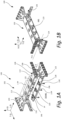
- FIG. 1A, 1B and 1C illustrate by way of example a cross member arrangement 100.
- the main piece 100 can comprise a first peripheral section 104 and a second peripheral section 106.
- the first peripheral section 104 can be attached to a first beam 108 (illustrated in FIG. 1C ) and the second peripheral section 106 can be attached to a second beam 110 (also illustrated in FIG. 1C ).
- a mid-section 112 can be provided between the first and second peripheral section 104, 106.
- This mid-section 112 may in turn comprise a first transverse plate sub-section 114 placed in a first transverse plane 1-TP and a longitudinal plate sub-section 116 placed in a longitudinal plane LP.
- a first side 118 (illustrated in further detail in FIG.1C ) of the longitudinal plate sub-section 116 may connect the first transverse plate sub-section 114 such that a T-shaped cross-section in a transversal direction T-D is formed.
- the longitudinal plate sub-section 116 may be provided with transversal recesses 120. In the example illustrated, three transversal recesses 120 are provided, but the number of recesses as well as how these are shaped may be different in other examples. One reason for having more recesses and also differently shaped recesses may be to better meet geometrical properties of electrical cables and/or electric components to be housed within the recesses.
- a second transverse plate piece 122 may be provided. As illustrated, this piece may be placed in a second transversal plane 2-TP, parallel with the first transversal plane 1-TP.
- DEMS demounted state
- the second transverse plate piece 122 and the main piece 102 can be de-attached. In this state, the transversal recesses 120 are easily accessible.
- the transversal recesses 120 are formed into transversal openings 123. Put differently, the recesses 120 are closed such that the cables placed in the recesses 120 are held securely in place.
- the cables can easily be replaced, re-organized or in any other way handled by first de-attaching the second transverse plate piece 122 such that the transversal openings 123 are changed into the transversal recesses 120, thereafter handle the cables, and once having the cables in place re-attach the second transverse plate piece 122.
- the cables and/or components may also be placed in a first peripheral passage 124 and/or a second peripheral passage 126.
- the first peripheral passage 124 can be formed by having the first peripheral section 104 U-shaped and having an open section of this section facing the first beam 108.
- the second peripheral section 106 can be U-shaped with an open section facing the second beam 110.
- the second transverse plate piece 122 may be attached to the main piece 102, more specifically the longitudinal plate sub-section 116 of the main piece 102, by having holes 128 provided in the second transverse plate piece 122 such that bolts 130 can be inserted via these holes into threaded holes 131 provided in the longitudinal plate sub-section 116.
- the cross member arrangement 100 comprising the main piece 102 and the second transverse plate piece 122, may in the mounted state MS be symmetric with respect to a longitudinal symmetry line L-S. Further, the first and second peripheral section 104, 106 may be symmetric with respect to a transversal symmetry line T-S. The cross member arrangement 100 may also be symmetric with respect to the transversal symmetry line T-S in the mounted state MS.
- the cross member arrangement 100 can be formed such that a peripheral vertical distance PVD, extending between a first peripheral vertical end 132 and a second peripheral vertical end 134, is greater than a mid-section vertical distance MSVD, extending between a first mid-section vertical end 138 and a second mid-section vertical end 140.
- a distance between the end points of the peripheral sections 104, 106 may be greater than a distance between the end points of the mid-section 112.
- a first space 142 abutting the first transverse plate sub-section 114 and a second space 144 abutting the second transverse plate piece 122 can be formed.
- first and second space 142 144 electric components can be housed.
- openings may be provided in the cross-member arrangement 100 for facilitating mounting of such components.
- the main piece 102 may be casted in one piece, or in any other way three-dimensionally shaped as one piece.
- this also comes with the advantage that rivets or other protruding attachment elements can be avoided on an outer surface 148 of the first transverse plate sub-section 114. Having the outer surface void of protruding attachment elements reduces the risk that cables may stuck or are damaged during routing.
- the cross member arrangement 100 may together with the first and second beam 108, 110 form a frame 152, which in turn forms part of a chassis 150.
- cables 154 may be provided in the transversal openings 123, but as discussed above, cables and/or components may also be provided in the first and/or second space 142, 144 and/or in the first and/or second peripheral passage 132, 134.
- the cables 154 may be secured to the second transverse plate piece 122 by using cable ties 156.
- cable ties 156 By using the cable ties 156, it is made possible to first attach, or secure, the cables 154 to the second transverse plate piece 122 while this piece is de-attached from the main piece 102. Once the cables 154 are secured, the second transverse plate piece 122, together with the cables 154, can be attached to the main piece 102.
- a service technician it is made easy for a service technician to organize the cables 154. In addition to an ergonomic working position, the service technician is also provided with a better overview of the cables 154.
- FIG. 2 illustrates a vehicle 200, herein exemplified by a truck, provided with the chassis 150 in turn comprising the cross member arrangement 100 illustrated in FIG. 1A - C .
- FIG. 3 is a flowchart illustrating a method 300 for producing the chassis 150.
- the first and second beam 108, 110 may be provided.
- the cross member arrangement 100 may be provided. After the first beam 108 and the cross member arrangement 100 are provided, the cross member arrangement 100 may be attached to the first beam 108 in a step 306. In a similar manner, the cross member arrangement 100 may be attached to the second beam 110 in a step 308.
- the cables 154 may be provided in the transversal recesses 120 in the cross member arrangement 100. After the cables 154 are provided, in a step 312, the second transverse plate piece 122 may be attached such that the transversal recesses 120 are formed into the transversal openings 123.
- FIG. 4 is a flowchart illustrating a method 400 for re-routing the cables 154 in the vehicle 200.
- re-routing should be interpreted broadly and it should be understood to include changing the routing of existing cables, but also adding or removing cables.
- the second transverse plate piece 122 may be de-attached. By de-attaching this piece, the transversal openings 123 are formed into the transversal recesses 120, thereby making the cables 154 held in the cross member arrangement 100 easily accessible to e.g. a service technician.
- the cables 154 can be re-arranged, e.g. re-routed, replaced, removed, added etc.
- the second transverse plate piece 122 can be attached.
- the transversal recesses 120 are formed into the transversal openings 123, thereby securing the cables 154.
- the cables 154 can be secured to the second transverse plate piece 122 by using the cable ties 156.
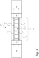
- FIG. 5 provides a general illustration of the cross member arrangement 100 in the mounted state MS, i.e. with the second transverse plate piece 122 attached to the main piece 102.
- the main piece 102 may comprise a first peripheral section 104 and a second peripheral section 106.
- the first peripheral section 104 may be attached to the first beam 108
- the second peripheral section 106 may be attached to the second beam 110.
- the first transverse plate sub-section 114 of the mid-section 112 may be arranged in the first transverse plane 1-TP.
- the longitudinal plate sub-section 116 of the mid-section 112 may be placed in a longitudinal plane LP.
- the first side 118 of the longitudinal plate sub-section 116 may abut the first transverse plate sub-section 114.
- the transversal recesses 120 may be provided in the longitudinal plate sub-section 116. In mounted state MS, as illustrated, the transversal recesses 120 may be formed into the transversal openings 123 by attaching the second transverse plate piece 122.
- Relative terms such as “below” or “above” or “upper” or “lower” or “horizontal” or “vertical” may be used herein to describe a relationship of one element to another element as illustrated in the Figures. It will be understood that these terms and those discussed above are intended to encompass different orientations of the device in addition to the orientation depicted in the Figures. It will be understood that when an element is referred to as being “connected” or “coupled” to another element, it can be directly connected or coupled to the other element, or intervening elements may be present. In contrast, when an element is referred to as being “directly connected” or “directly coupled” to another element, there are no intervening elements present.
Landscapes
- Engineering & Computer Science (AREA)
- Chemical & Material Sciences (AREA)
- Combustion & Propulsion (AREA)
- Transportation (AREA)
- Mechanical Engineering (AREA)
- Architecture (AREA)
- Structural Engineering (AREA)
- Body Structure For Vehicles (AREA)
- Installation Of Indoor Wiring (AREA)
Priority Applications (2)
| Application Number | Priority Date | Filing Date | Title |
|---|---|---|---|
| EP22206340.6A EP4368478A1 (de) | 2022-11-09 | 2022-11-09 | Querträgeranordnung |
| US18/489,931 US12612108B2 (en) | 2022-11-09 | 2023-10-19 | Cross member arrangement |
Applications Claiming Priority (1)
| Application Number | Priority Date | Filing Date | Title |
|---|---|---|---|
| EP22206340.6A EP4368478A1 (de) | 2022-11-09 | 2022-11-09 | Querträgeranordnung |
Publications (1)
| Publication Number | Publication Date |
|---|---|
| EP4368478A1 true EP4368478A1 (de) | 2024-05-15 |
Family
ID=89844072
Family Applications (1)
| Application Number | Title | Priority Date | Filing Date |
|---|---|---|---|
| EP22206340.6A Pending EP4368478A1 (de) | 2022-11-09 | 2022-11-09 | Querträgeranordnung |
Country Status (2)
| Country | Link |
|---|---|
| US (1) | US12612108B2 (de) |
| EP (1) | EP4368478A1 (de) |
Families Citing this family (1)
| Publication number | Priority date | Publication date | Assignee | Title |
|---|---|---|---|---|
| EP4368478A1 (de) * | 2022-11-09 | 2024-05-15 | Volvo Truck Corporation | Querträgeranordnung |
Citations (4)
| Publication number | Priority date | Publication date | Assignee | Title |
|---|---|---|---|---|
| US20050116459A1 (en) * | 2002-03-05 | 2005-06-02 | Jun Ito | Connection structure of side member to cross member |
| CN103085877A (zh) * | 2011-11-04 | 2013-05-08 | 北汽福田汽车股份有限公司 | 一种车架结构及该车架结构的安装方法 |
| CN110937021A (zh) * | 2019-12-17 | 2020-03-31 | 东风商用车有限公司 | 一种无驾驶室的电动运输车底盘车架 |
| CN112550461A (zh) * | 2020-12-23 | 2021-03-26 | 安徽华菱汽车有限公司 | 一种重卡牵引车型车架及重卡牵引车 |
Family Cites Families (13)
| Publication number | Priority date | Publication date | Assignee | Title |
|---|---|---|---|---|
| SE511491C2 (sv) * | 1998-02-26 | 1999-10-04 | Scania Cv Ab | Balkanordning |
| BE1012376A6 (nl) * | 1999-01-05 | 2000-10-03 | Groep Stevens Int Nv | Werkwijze voor het vervaardigen van een dwarsligger en voertuigonderstel voorzien van dergelijke dwarsligger. |
| JP4064641B2 (ja) | 2001-04-13 | 2008-03-19 | 矢崎総業株式会社 | クリップ及びクリップの取付構造 |
| WO2007106913A2 (en) * | 2006-03-16 | 2007-09-20 | Hendrickson International Corporation | Frame for heavy-duty vehicles |
| US10215263B2 (en) * | 2016-06-28 | 2019-02-26 | Reyco Granning, Llc | Air spring actuated slider for semi-trailer |
| WO2019038788A2 (en) * | 2017-08-25 | 2019-02-28 | Metalsa India Private Limited | IMPROVED TRANSVERSE ELEMENT AND TRANSVERSE ELEMENT ASSEMBLY FOR VEHICLE FRAME |
| US11155148B2 (en) | 2019-04-05 | 2021-10-26 | Ford Global Technologies, Llc | Integrated mounting systems for mounting electric drive components within electrified vehicles |
| EP3967116A1 (de) * | 2019-05-10 | 2022-03-16 | Volvo Truck Corporation | System zum anordnen von ecu in einem fahrgestell eines fahrzeugs |
| CN211223604U (zh) | 2019-12-17 | 2020-08-11 | 东风商用车有限公司 | 一种无驾驶室的电动运输车底盘车架 |
| CN113879400B (zh) | 2021-10-28 | 2022-11-08 | 泰安航天特种车有限公司 | 一种适用于重型电驱特种车底盘的车架结构 |
| US12473028B2 (en) * | 2022-03-01 | 2025-11-18 | Daimler Truck North America Llc | Vehicle chassis crossmember apparatuses and methods thereof |
| EP4368478A1 (de) * | 2022-11-09 | 2024-05-15 | Volvo Truck Corporation | Querträgeranordnung |
| EP4552950A1 (de) * | 2023-11-08 | 2025-05-14 | Volvo Truck Corporation | Querträger, chassisrahmen, fahrzeug, montage- und demontageverfahren im zusammenhang damit |
-
2022
- 2022-11-09 EP EP22206340.6A patent/EP4368478A1/de active Pending
-
2023
- 2023-10-19 US US18/489,931 patent/US12612108B2/en active Active
Patent Citations (4)
| Publication number | Priority date | Publication date | Assignee | Title |
|---|---|---|---|---|
| US20050116459A1 (en) * | 2002-03-05 | 2005-06-02 | Jun Ito | Connection structure of side member to cross member |
| CN103085877A (zh) * | 2011-11-04 | 2013-05-08 | 北汽福田汽车股份有限公司 | 一种车架结构及该车架结构的安装方法 |
| CN110937021A (zh) * | 2019-12-17 | 2020-03-31 | 东风商用车有限公司 | 一种无驾驶室的电动运输车底盘车架 |
| CN112550461A (zh) * | 2020-12-23 | 2021-03-26 | 安徽华菱汽车有限公司 | 一种重卡牵引车型车架及重卡牵引车 |
Also Published As
| Publication number | Publication date |
|---|---|
| US20240149946A1 (en) | 2024-05-09 |
| US12612108B2 (en) | 2026-04-28 |
Similar Documents
| Publication | Publication Date | Title |
|---|---|---|
| US20240190232A1 (en) | System and method for installation of traction batteries for a vehicle | |
| US11518438B2 (en) | Vehicle frame structure | |
| EP2318800A1 (de) | Modulare architektur für ein kampffahrzeug | |
| FI127328B (en) | Arrangement for installing a mobile telescopic energy device | |
| CA2420300C (en) | Undercar assembly for a railcar | |
| US12496886B2 (en) | Floor assembly for a motor vehicle, motor vehicle and method for producing a floor assembly | |
| US12612108B2 (en) | Cross member arrangement | |
| US20250229717A1 (en) | Sub-Frame and Step Assembly for Truck | |
| US7980594B2 (en) | Chassis frame especially for a heavy vehicle | |
| US20250229618A1 (en) | Bracket assembly for attaching component to vehicle | |
| CN211642185U (zh) | 一种转向架端部复合支架 | |
| WO2000063060A1 (en) | Load carrying arrangement for a vehicle | |
| EP1270374A2 (de) | Querträger für die Radaufhängung eines Kraftfahrzeuges | |
| EP3953977B1 (de) | System zum befestigen eines batteriepacks an einem fahrzeugrahmen | |
| WO2015088421A1 (en) | Arrangement for facilitating the fitting of a vehicle module | |
| CN116533824B (zh) | 快换支架及包含其的电动车辆 | |
| CN204137226U (zh) | 四轮车车架 | |
| CA2881215A1 (en) | Multifunctional fastening profile | |
| CN105313658A (zh) | 电池支撑总成 | |
| CN220190126U (zh) | 一种apm车辆电气柜框架结构 | |
| CN216783433U (zh) | 一种底部防护结构及矿用自卸车 | |
| CN105857049A (zh) | 一种电传动矿用自卸车动力支座 | |
| US12617467B2 (en) | Transverse cross-member assembly and mounting methods for a vehicle chassis | |
| CN213323340U (zh) | 一种重型卡车横梁总成 | |
| CN214001641U (zh) | 铁路检修车底板车架 |
Legal Events
| Date | Code | Title | Description |
|---|---|---|---|
| PUAI | Public reference made under article 153(3) epc to a published international application that has entered the european phase |
Free format text: ORIGINAL CODE: 0009012 |
|
| STAA | Information on the status of an ep patent application or granted ep patent |
Free format text: STATUS: THE APPLICATION HAS BEEN PUBLISHED |
|
| AK | Designated contracting states |
Kind code of ref document: A1 Designated state(s): AL AT BE BG CH CY CZ DE DK EE ES FI FR GB GR HR HU IE IS IT LI LT LU LV MC ME MK MT NL NO PL PT RO RS SE SI SK SM TR |
|
| STAA | Information on the status of an ep patent application or granted ep patent |
Free format text: STATUS: REQUEST FOR EXAMINATION WAS MADE |
|
| 17P | Request for examination filed |
Effective date: 20241114 |
|
| RBV | Designated contracting states (corrected) |
Designated state(s): AL AT BE BG CH CY CZ DE DK EE ES FI FR GB GR HR HU IE IS IT LI LT LU LV MC ME MK MT NL NO PL PT RO RS SE SI SK SM TR |