EP4368806A1 - Verbinder zum verbinden von hohlprofilen - Google Patents
Verbinder zum verbinden von hohlprofilen Download PDFInfo
- Publication number
- EP4368806A1 EP4368806A1 EP23209853.3A EP23209853A EP4368806A1 EP 4368806 A1 EP4368806 A1 EP 4368806A1 EP 23209853 A EP23209853 A EP 23209853A EP 4368806 A1 EP4368806 A1 EP 4368806A1
- Authority
- EP
- European Patent Office
- Prior art keywords
- connector
- profile
- designed
- connecting element
- cooling element
- Prior art date
- Legal status (The legal status is an assumption and is not a legal conclusion. Google has not performed a legal analysis and makes no representation as to the accuracy of the status listed.)
- Granted
Links
Images


Classifications
-
- E—FIXED CONSTRUCTIONS
- E06—DOORS, WINDOWS, SHUTTERS, OR ROLLER BLINDS IN GENERAL; LADDERS
- E06B—FIXED OR MOVABLE CLOSURES FOR OPENINGS IN BUILDINGS, VEHICLES, FENCES OR LIKE ENCLOSURES IN GENERAL, e.g. DOORS, WINDOWS, BLINDS, GATES
- E06B3/00—Window sashes, door leaves, or like elements for closing wall or like openings; Layout of fixed or moving closures, e.g. windows in wall or like openings; Features of rigidly-mounted outer frames relating to the mounting of wing frames
- E06B3/96—Corner joints or edge joints for windows, doors, or the like frames or wings
- E06B3/964—Corner joints or edge joints for windows, doors, or the like frames or wings using separate connection pieces, e.g. T-connection pieces
-
- E—FIXED CONSTRUCTIONS
- E06—DOORS, WINDOWS, SHUTTERS, OR ROLLER BLINDS IN GENERAL; LADDERS
- E06B—FIXED OR MOVABLE CLOSURES FOR OPENINGS IN BUILDINGS, VEHICLES, FENCES OR LIKE ENCLOSURES IN GENERAL, e.g. DOORS, WINDOWS, BLINDS, GATES
- E06B3/00—Window sashes, door leaves, or like elements for closing wall or like openings; Layout of fixed or moving closures, e.g. windows in wall or like openings; Features of rigidly-mounted outer frames relating to the mounting of wing frames
- E06B3/04—Wing frames not characterised by the manner of movement
- E06B3/263—Frames with special provision for insulation
- E06B3/26301—Frames with special provision for insulation with prefabricated insulating strips between two metal section members
- E06B3/26303—Frames with special provision for insulation with prefabricated insulating strips between two metal section members with thin strips, e.g. defining a hollow space between the metal section members
-
- E—FIXED CONSTRUCTIONS
- E06—DOORS, WINDOWS, SHUTTERS, OR ROLLER BLINDS IN GENERAL; LADDERS
- E06B—FIXED OR MOVABLE CLOSURES FOR OPENINGS IN BUILDINGS, VEHICLES, FENCES OR LIKE ENCLOSURES IN GENERAL, e.g. DOORS, WINDOWS, BLINDS, GATES
- E06B3/00—Window sashes, door leaves, or like elements for closing wall or like openings; Layout of fixed or moving closures, e.g. windows in wall or like openings; Features of rigidly-mounted outer frames relating to the mounting of wing frames
- E06B3/96—Corner joints or edge joints for windows, doors, or the like frames or wings
- E06B3/964—Corner joints or edge joints for windows, doors, or the like frames or wings using separate connection pieces, e.g. T-connection pieces
- E06B3/968—Corner joints or edge joints for windows, doors, or the like frames or wings using separate connection pieces, e.g. T-connection pieces characterised by the way the connecting pieces are fixed in or on the frame members
- E06B3/9681—Corner joints or edge joints for windows, doors, or the like frames or wings using separate connection pieces, e.g. T-connection pieces characterised by the way the connecting pieces are fixed in or on the frame members by press fit or adhesion
- E06B3/9682—Mitre joints
-
- E—FIXED CONSTRUCTIONS
- E06—DOORS, WINDOWS, SHUTTERS, OR ROLLER BLINDS IN GENERAL; LADDERS
- E06B—FIXED OR MOVABLE CLOSURES FOR OPENINGS IN BUILDINGS, VEHICLES, FENCES OR LIKE ENCLOSURES IN GENERAL, e.g. DOORS, WINDOWS, BLINDS, GATES
- E06B5/00—Doors, windows, or like closures for special purposes; Border constructions therefor
- E06B5/10—Doors, windows, or like closures for special purposes; Border constructions therefor for protection against air-raid or other war-like action; for other protective purposes
- E06B5/16—Fireproof doors or similar closures; Adaptations of fixed constructions therefor
-
- E—FIXED CONSTRUCTIONS
- E06—DOORS, WINDOWS, SHUTTERS, OR ROLLER BLINDS IN GENERAL; LADDERS
- E06B—FIXED OR MOVABLE CLOSURES FOR OPENINGS IN BUILDINGS, VEHICLES, FENCES OR LIKE ENCLOSURES IN GENERAL, e.g. DOORS, WINDOWS, BLINDS, GATES
- E06B3/00—Window sashes, door leaves, or like elements for closing wall or like openings; Layout of fixed or moving closures, e.g. windows in wall or like openings; Features of rigidly-mounted outer frames relating to the mounting of wing frames
- E06B3/04—Wing frames not characterised by the manner of movement
- E06B3/263—Frames with special provision for insulation
- E06B2003/26394—Strengthening arrangements in case of fire
Definitions
- the present invention relates generally to profile arrangements, in particular facades or skylights, in fire protection design.
- a profile arrangement of the generic type is used, for example, in facade or window systems, preferably to connect two profiles "butt joint".
- a so-called butt connector is used here, which is attached to the first profile and inserted into a cavity in the second profile and fixed there.
- the butt connector is first connected to the first profile by means of a positive connection, for example by a combination of a T-shaped profile of the butt connector and a C-shaped groove of the first profile. Essentially, the butt connector can initially be moved in the groove, but can no longer be pulled out. Finally, the butt connector is fixed in one position, usually by means of a so-called punch screw.
- the punch screw has a screw head, a threaded section and a punch pin.
- the punch pin is cylindrical and has a smaller diameter, primarily a significantly smaller diameter, than the threaded section.
- corner connector In order to connect two mitred hollow profiles, it is known from facade construction to use a single or multi-part corner connector.
- a corner connector is known from the publication EP 2 154 323 A2 It can be used to form a connection between two mitred hollow profiles.
- the corner connector is inserted into the hollow profiles.
- An adhesive is inserted between the corner connector and the hollow profiles so that a reliable connection is created.
- the invention is based on the object of specifying a connector for connecting hollow profiles, in particular for facades, roofs, windows or doors, wherein the connector is designed in fire protection design, whereby the achievable load-bearing capacity of the connector is nevertheless not reduced.
- the invention relates in particular to a connector for connecting hollow profiles, in particular for facades, roofs, windows or doors, wherein the connector has at least one connecting element made of metal, in particular light metal such as aluminum, and at least one cooling element made of a heat-binding material.
- the at least one cooling element is arranged directly adjacent to a side surface, in particular an inner and/or outer side surface, of the connecting element.
- the at least one cooling element is arranged in a gap between in particular the outer side surface of the connecting element and an inner side surface of one of the hollow profiles to be connected to the connector.
- the at least one cooling element is inserted into the gap between the outer side surface of the connecting element and the inner side surface of the hollow profile, in particular after the connecting element has been connected to the hollow profile.
- the at least one cooling element is connected to the connecting element via at least one outer side surface of the connecting element, in particular is connected in a form-fitting and/or force-fitting manner.
- the at least one cooling element can be connected to the connecting element, in particular positively and/or non-positively, via at least one outer side surface of the connecting element.
- the connector has a connecting element made in particular from aluminum, an increased load-bearing capacity of the connecting area of the hollow profiles can be achieved while reducing the weight of the connector. Since the melting point of the material of the connecting element is lower than the temperature expected to affect the hollow profiles in the event of a fire, a cooling element connected to the connecting element from the outside is provided to prevent the connecting element from melting. With the help of this cooling element, failure of the connector in the event of a fire can be effectively prevented for a predetermined safety period.
- cooling element is arranged on at least one outer side surface of the connecting element with the connecting element or in particular is connected in a form-fitting and/or force-fitting manner, the actual connecting element is structurally unchanged and the necessary load-bearing capacity of the connecting area can be maintained with the connecting element.
- the cooling element is designed as a plate that covers at least part or all of the outside surface of the connecting element or a similar shaped body made of a heat-binding, hydrophilic adsorber with a high water content.
- the cooling element is made as a shaped body from a heat-binding, hydrophilic adsorber with a high water content, the adsorber preferably containing alum and gypsum.
- the alum is a so-called metal double salt, which is able to store crystal water to a very high degree relative to its weight.
- potassium alum which is chemically known as potassium aluminum sulfate 12 hydrate. This potassium alum is able to physically bind approx. 45% of crystal water per unit weight. The release of crystal water from the potassium alum in pure form occurs at 73°C. Due to the density of the alum of 1.1 g/cm 3 , the volume-related proportion of the stored crystal water is approx. 50%.
- the potassium alum is embedded in a gypsum matrix and behaves completely neutrally with regard to the hardening of the gypsum, so that the molded parts made from it have sufficient stability for their use in fire protection.
- such molded parts can be easily arranged or connected, preferably in a form-fitting and/or force-fitting manner, to at least one outer surface of the connecting element to be protected.
- the molded parts used as coolants which are provided with a hydrophilic adsorber, preferably consist of 50% modified gypsum and 50% potassium alum. Since the gypsum and the alum have a density of 1.1 g/cm 3 , this ratio is based on weight and volume. The energy consumption of such a molded part serving as a coolant is approximately 1,100 J/cm 3 .
- potassium alum on its own has an effective temperature of 73°C, the effective temperature in combination with the gypsum is shifted to a higher value, namely approximately 85°C.
- the combination of gypsum and alum has the additional advantage that the crystal water bound in the gypsum is only released at an effective temperature of 125°C and this multi-stage crystal water release has a positive effect on the cooling process of the connecting element, which is provided with the corresponding cooling element. In addition, at around 215°C there is another small release of water bound in the gypsum, but this is of minor importance.
- the present invention is not limited to coolants consisting of potassium alum in a gypsum matrix.
- Other possible water-based coolants are commercially available, for example, under the name Palstop Pax H, Roku V2, Roku V3, Roku ENEX, Kerafix 2002002 or Roku Coolfix 1000, Promaxon Type A, Promatect L.
- the cooling element advantageously has at least one material formation which interacts in a form-fitting and/or force-fitting manner with at least one material formation of the connecting element which is at least partially and/or regionally complementary to the material formation of the cooling element.
- the cooling element can be clipped into at least one groove of the connecting element.
- the cooling element is designed as a shaped body, for example in the form of a plate, which covers at least one outer side surface of the connecting element at least partially or in regions.
- the connector can be designed, for example, as a butt connector for the angled connection of hollow profiles each comprising a connecting profile and a plug-on profile.
- the connecting element of the connector designed as a butt connector is or can be fastened to the connecting profile, in particular by means of pins or screws, wherein when the plug-on profile is attached, the connecting element with the at least one cooling element is accommodated in the plug-on profile designed as a hollow profile.
- the connector is designed as a corner connector for connecting two mitred hollow profiles.
- the connecting element can have two sections that adjoin one another in a corner area, with the corner area being arranged in the area of the miter joint when connecting the hollow profiles.
- the at least one cooling element when the connector is designed as a corner connector, it is advisable for the at least one cooling element to cover at least partially and/or in regions and preferably completely a particularly common outer side surface of the two sections of the connecting element.
- the invention further relates to an arrangement comprising a connecting profile designed as a hollow profile, a plug-on profile designed as a hollow profile and a connector designed as a butt connector of the aforementioned type according to the invention, wherein the connecting profile and the plug-on profile are connected to one another using the butt connector.
- connection profile is designed as an inner shell of a heat-separated profile arrangement, in which the connection profile is connected to a hollow profile designed as an outer shell via insulating webs.
- the at least one coolant should preferably be arranged on an outer side surface of the butt connector facing away from the hollow profile designed as an outer shell.
- the invention further relates to an arrangement comprising two mitred hollow profiles and a connector designed as a corner connector of the aforementioned type according to the invention, wherein the two mitred hollow profiles are connected to one another using the corner connector accommodated within the hollow profiles.
- the two mitred hollow profiles are each designed as the inner shell of a heat-separated profile arrangement, in which the hollow profile designed as the inner shell is connected to a hollow profile designed as the outer shell via insulating webs.
- the at least one cooling element is arranged on an outer side surface of the corner connector facing away from the hollow profile designed as the outer shell.
- the profile arrangement essentially comprises a first profile, which is designed as a connecting profile 4, and a second profile, which is designed as a clip-on profile.
- the connecting profile 4 is designed as the inner shell of a thermally separated profile arrangement, in which the connecting profile 4 is connected to a profile designed as an outer shell via insulating webs.
- the clip-on profile is also designed as the inner shell of a thermally separated profile arrangement, in which the clip-on profile is connected to a profile designed as an outer shell via insulating webs.
- the profiles are preferably elongated profiles, in particular hollow profiles, preferably made of aluminium.
- the clip-on profile is preferably perpendicular to the connecting profile 4 and has at least one hollow profile section or one hollow chamber.
- connection profile 4 the connection profile 4 and the plug-on profile.
- the butt connector 1 is a molded part which is attached to the connecting profile 4, whereby the butt connector 1 can be inserted into the hollow chamber of the clip-on profile 5 and attached to the clip-on profile.
- the butt connector 1 is a machined extruded connecting element made of, for example, aluminum with a substantially rectangular cross-section.
- the butt connector 1 further comprises a coolant 3 made of a heat-binding material.
- the coolant 3 is connected to the connecting element 2 via an outer and/or inner side surface of a connecting element 2 of the butt connector 1, in particular in a form-fitting and/or force-fitting manner.
- the cooling element can be clipped into at least one groove of the connecting element 2.
- FIG. 1A , B to FIG. 3A , B embodiments of the connector 1 according to the invention are shown, wherein in these embodiments the connector 1 is designed as a butt connector 1 for the angular connection of hollow profiles each comprising a connection profile 4 and a plug-on profile.
- the exemplary embodiment of the connector designed as a butt connector 1 is characterized in that the connector 1 has a connecting element 2 made of metal, in particular light metal such as aluminum, and at least one cooling element 3 made of a heat-binding material. It is provided that the at least one cooling element 3 is connected to the connecting element 2 via at least one outer and/or inner side surface of the connecting element 2, in particular in a form-fitting and/or force-fitting manner.
- the cooling element 3 is designed as a shaped body, in particular in the form of a plate, which covers at least one outer surface of the connecting element 2 at least partially or in regions.
- the heat-binding material of the cooling element is in particular a heat-binding, hydrophilic adsorber material with a high water content. It is advisable for the heat-binding, hydrophilic adsorber material to contain alum and preferably potassium alum, which can be incorporated into a gypsum matrix.
- the connector designed there as a butt connector 1 is provided with the already mentioned connecting element 2, wherein the connecting element 2 is fastened to the connection profile 4 by means of pins or screws 6.
- the connecting element 2 with the at least one cooling element 3 is accommodated in the plug-on profile designed as a hollow profile.
- the at least one cooling element 3 at least partially and/or regionally and preferably completely covers a particularly common outer side surface of the two sections of the connecting element 2.
- the present invention is not limited to this embodiment.
- the at least one cooling element 3 covers an inner side surface of the connecting element 2.
- FIG. 4 to FIG. 6 Another design variant of the profile arrangement in fire protection design is shown schematically and in an isometric exploded view.
- the two mitred hollow profiles are each designed as the inner shell of a thermally separated profile arrangement, in which the hollow profile designed as the inner shell is connected via insulating webs to a profile designed as the outer shell, in particular a hollow profile.
- the connector 1 designed as a corner connector is again provided with a cooling element 3, which is connected to the connecting element 2 via an outer and/or inner side surface of the connecting element 2, in particular in a form-fitting and/or force-fitting manner.
- FIG.4A , B, FIG. 5A , Federation FIG.6A , B shows an alternative embodiment of the connector 1 according to the invention for connecting hollow profiles, in particular for facades, roofs, windows or doors.
- the connector 1 is not designed as a butt connector, but as a corner connector for connecting two mitred hollow profiles.
- the connector 1 has a connecting element 2 made of metal, in particular light metal such as aluminum, wherein the connecting element 2 has two sections which adjoin one another in a corner region, and wherein the corner region is arranged in the region of the miter joint when connecting the hollow profiles.
- connection element 2 of the corner connector which is made in particular of aluminum, is additionally provided with at least one cooling element 3.
- the cooling element 3 is arranged on an outer side surface of a section of the connecting element 2, while in the embodiment shown in FIG. 5A , B, the cooling element 3 is arranged on an inner side surface of a portion of the connecting element 2.
- corresponding cooling elements are arranged both on the outer side surface and on the inner side surface of the connecting element 2.
Landscapes
- Engineering & Computer Science (AREA)
- Civil Engineering (AREA)
- Structural Engineering (AREA)
- Joining Of Building Structures In Genera (AREA)
- Building Environments (AREA)
- Mutual Connection Of Rods And Tubes (AREA)
- Special Wing (AREA)
Abstract
Description
- Die vorliegende Erfindung betrifft allgemein Profilanordnungen, insbesondere Fassaden oder Lichtdächer, in Brandschutzausführung.
- Eine Profilanordnung der gattungsgemäßen Art wird beispielsweise in Fassaden- oder Fenstersystemen eingesetzt, vorzugsweise um zwei Profile "auf Stoß" miteinander zu verbinden. Hierbei kommt ein so genannter Stoßverbinder zum Einsatz, der auf dem ersten Profil befestigt wird und in einen Hohlraum des zweiten Profils eingeschoben und dort fixiert wird.
- Der Stoßverbinder wird zunächst mittels einer formschlüssigen Verbindung, beispielsweise durch eine Kombination aus einem T-förmigen Profil des Stoßverbinders und einer C-förmigen Nut des ersten Profils, mit dem ersten Profil verbunden. Im Wesentlichen lässt sich der Stoßverbinder zunächst noch in der Nut verschieben, aber nicht mehr herausziehen. Schlussendlich wird der Stoßverbinder in einer Position in der Regel mittels einer so genannten Stanzschraube fixiert. Die Stanzschraube weist einen Schraubenkopf, einen Gewindeabschnitt und einen Stanzzapfen auf. Der Stanzzapfen ist zylindrisch ausgebildet und weist einen geringeren Durchmesser, vornehmlich einen erheblich geringeren Durchmesser, als der Gewindeabschnitt auf.
- Um zwei auf Gehrung geschnittene Hohlprofile zu verbinden, ist es aus dem Fassadenbau bekannt, einen ein- oder mehrteiligen Eckverbinder einzusetzen. Beispielsweise ist ein solcher Eckverbinder aus der Druckschrift
EP 2 154 323 A2 bekannt. Er kann zur Ausbildung einer Verbindung zweier auf Gehrung geschnittener Hohlprofile verwendet werden. Der Eckverbinder wird in die Hohlprofile eingebracht. Ein Klebstoff wird so zwischen Eckverbinder und den Hohlprofilen eingebracht, dass eine zuverlässige Verbindung erfolgt. - Damit eine Profilanordnung und insbesondere eine Fassaden- oder Fensteranordnung die Anforderungen des Brandschutzes erfüllen kann, sind Maßnahmen zur Verminderung der Entstehung bzw. der Ausbreitung eines Brandes vorzusehen. Schwachstellen innerhalb eines Fassadensystems, beispielsweise bei einer vorgehängten Fassade, sind ungeteilte Pfosten und Riegel im Bereich von Decken oder Trennwänden, deren Anschlüsse an den Baukörper, und insbesondere Eck- oder Stoßverbinder, die zum Verbinden von zwei Hohlprofilen dienen. Im Brandfall müssen aufgrund hoher Temperaturen in diesen Bereichen Verformungen konstruktiv kompensiert werden. Zur Reduzierung der Hitzeausbreitung können unter anderem Materialien Einsatz finden, die unter Hitze aufschäumen und abdichten, oder auch verdampfende Materialien, welche die Hitzeausbreitung reduzieren.
- Problematisch ist jedoch der Einsatz derartiger Materialien im Bereich eines Stoß- oder Eckverbinders, da in diesem Bereich konstruktionsbedingt nur ein relativ geringer Bauraum zur Verfügung steht. Die Integration derartiger die Hitzeausbreitung reduzierender Materialien in einem Eck- oder Stoßverbinder sorgt zwangsläufig dazu, dass der Eck- oder Stoßverbinder kleiner ausgeführt werden muss, was letztendlich nachteilig für die erzielbare Tragfähigkeit der Fenster- bzw. Fassadenkonstruktion ist.
- Ausgehend von dieser Problemstellung liegt der Erfindung die Aufgabe zu Grunde, einen Verbinder zum Verbinden von Hohlprofile, insbesondere für Fassaden, Dächer, Fenster oder Türen, anzugeben, wobei der Verbinder in Brandschutzausführung ausgeführt ist, wobei dennoch die erzielbare Tragfähigkeit des Verbinders nicht reduziert wird.
- Diese Aufgabe wird erfindungsgemäß durch den Gegenstand des unabhängigen Patentanspruchs 1 gelöst.
- Demgemäß betrifft die Erfindung insbesondere einen Verbinder zum Verbinden von Hohlprofilen, insbesondere für Fassaden, Dächer, Fenster oder Türen, wobei der Verbinder mindestens ein aus Metall, insbesondere Leichtmetall wie Aluminium, gebildetes Verbindungselement und mindestens ein Kühlelement aus einem wärmebindenden Material aufweist.
- Diesbezüglich ist insbesondere vorgesehen, dass das mindestens eine Kühlelement unmittelbar benachbart zu einer Seitenfläche, insbesondere einer Innen- und/oder Außenseitenfläche, des Verbindungselements angeordnet ist.
- Insbesondere ist in diesem Zusammenhang vorgesehen, dass das mindestens eine Kühlelement in einen Spaltraum zwischen insbesondere der Außenseitenfläche des Verbindungselements und einer Innenseitenfläche eines der mit dem Verbinder zu verbindenden Hohlprofilen angeordnet ist.
- Denkbar ist es in diesem Zusammenhang, dass das mindestens eine Kühlelement in den Spaltraum zwischen der insbesondere Außenseitenfläche des Verbindungselements und der Innenseitenfläche des Hohlprofiles eingeschoben ist, insbesondere nach dem Verbinden des Verbindungselements mit dem Hohlprofil.
- Alternativ hierzu ist es auch denkbar, dass das mindestens eine Kühlelement über mindestens eine Außenseitenfläche des Verbindungselements mit dem Verbindungselement verbunden, insbesondere form- und/oder kraftschlüssig verbunden ist.
- Das mindestens eine Kühlelement kann beispielsweise über mindestens eine Außenseitenfläche des Verbindungselements mit dem Verbindungselement verbunden, insbesondere form- und/oder kraftschlüssig verbunden, sein.
- Die mit der Erfindung erzielbaren Vorteile liegen auf der Hand:
Dadurch, dass der Verbinder ein insbesondere aus Aluminium gebildetes Verbindungselement aufweist, kann bei Reduzierung des Gewichts des Verbinders eine erhöhte Tragfähigkeit des Verbindungsbereichs der Hohlprofile erzielt werden. Da der Schmelzpunkt des Materials des Verbindungselements niedriger liegt als die im Brandfall zu erwartende, die Hohlprofile beaufschlagende Temperatur, ist zum Verhindern eines Abschmelzens des Verbindungselements ein von außen mit dem Verbindungselement verbundenes Kühlelement vorgesehen. Mit Hilfe dieses Kühlelements kann wirksam ein Versagen des Verbinders im Brandfall über eine vorgegebene Sicherheitszeitdauer verhindert werden. - Dadurch, dass das Kühlelement an mindestens einer Außenseitenfläche des Verbindungselements mit dem Verbindungselement angeordnet oder insbesondere form- und/oder kraftschlüssig verbunden ist, ist das eigentliche Verbindungselement konstruktiv unverändert, und es kann mit dem Verbindungselement die notwendige Tragfähigkeit des Verbindungsbereichs beibehalten werden.
- Als Kühlelement kommen unterschiedliche Ausführungsformen in Frage. Beispielsweise ist es denkbar, dass das Kühlelement als eine die Außenseitenfläche des Verbindungselements zumindest teil- oder bereichsweise abdeckende Platte oder ein ähnlicher Formkörper aus einem wärmebindenden, hydrophilen Adsorber mit hohem Wasseranteil ausgeführt ist.
- Gemäß bevorzugten Realisierungen der erfindungsgemäßen Lösung ist vorgesehen, dass das Kühlelement als Formkörper aus einem wärmebindenden, hydrophilen Adsorber mit hohem Wasseranteil besteht, wobei der Adsorber vorzugsweise Alaun und Gips enthält. Beim Alaun handelt es sich um so genannte Metalldoppelsalze, die in der Lage sind, in sehr hohem Grad gewichtsbezogen Kristallwasser zu speichern.
- Es hat sich als zweckmäßig erweisen, Kalium-Alaun zu verwenden, welches chemisch als Kalium-Aluminium-Sulfat-12-Hydrat bezeichnet wird. Dieses Kalium-Alaun ist in der Lage, ca. 45% Kristallwasser pro Gewichtseinheit physikalisch zu binden. Das Freisetzen des Kristallwassers aus dem Kalium-Alaun in reiner Form erfolgt bei 73°C. Aufgrund der Dichte des Alauns von 1,1 g/cm3 ergibt sich volumenbezogen ein Anteil des eingelagerten Kristallwassers von ca. 50%.
- Denkbar in diesem Zusammenhang ist es beispielsweise, dass das Kalium-Alaun in eine Gipsmatrix eingebettet ist und sich bezüglich der Aushärtung des Gips völlig neutral verhält, so dass die daraus hergestellten Formteile ausreichende Stabilität für ihre Anwendung im Brandschutz besitzen. Insbesondere können derartige Formteile problemlos vorzugsweise form- und/oder kraftschlüssig an mindestens einer Außenseitenfläche des zu schützenden Verbindungselements angeordnet bzw. verbunden werden.
- Die als Kühlmittel dienenden Formteile, die mit einem hydrophilen Adsorber versehen sind, bestehen vorzugsweise zu 50% aus einem modifizierten Gips und zu 50% aus Kalium-Alaun. Da der Gips wie auch das Alaun eine Dichte von 1,1 g/cm3 haben, ist dieses Verhältnis gewichts- und volumenbezogen. Der Energieverzehr eines solchen als Kühlmittel dienenden Formteils beträgt ca. 1.100 J/cm3. Obwohl Kalium-Alaun für sich allein eine Wirktemperatur von 73°C hat, wird die Wirktemperatur in Verbindung mit dem Gips auf einen höheren Wert, nämlich ca. 85°C verlegt. Dies ergibt sich daraus, dass das im Alaun freiwerdende Wasser durch einfaches Aufsaugen durch den Gips bis zur Temperatur von 85°C gehalten wird, bevor es in die Dampfphase überführt wird. Es tritt hier eine günstige Wirktemperatur ein, die in ausreichender Distanz zu den Gebrauchstemperaturen liegt, die unter Umständen 70°C bei direkter Sonnenbestrahlung erreichen kann.
- Die Kombination von Gips und Alaun hat den weiteren Vorteil, dass das im Gips gebundene Kristallwasser erst bei einer Wirktemperatur von 125°C freigesetzt wird und sich diese mehrstufige Kristallwasserfreisetzung positiv auf den Kühlungsverlauf des Verbindungselements auswirkt, welches mit dem entsprechenden Kühlelement versehen ist. Darüber hinaus findet bei ca. 215°C eine nochmalige geringe Freisetzung von im Gips gebundenem Wasser statt, die aber von eher untergeordneter Bedeutung ist.
- Selbstverständlich ist die vorliegende Erfindung jedoch nicht auf Kühlmittel beschränkt, die aus Kalium-Alaun in einer Gipsmatrix bestehen. Weitere mögliche wassergebundene Kühlmittel sind kommerziell beispielsweise unter der Bezeichnung Palstop Pax H, Roku V2, Roku V3, Roku ENEX, Kerafix 2002002 bzw. Roku Coolfix 1000, Promaxon Typ A, Promatect L.
- In vorteilhafter Weise weist das Kühlelement mindestens eine Materialausformung auf, die form- und/oder kraftschlüssig mit mindestens einer zur Materialausformung des Kühlelements zumindest teil- und/oder bereichsweise komplementär ausgeführten Materialausformung des Verbindungselements zusammenwirkt. In einer denkbaren Realisierung dieser Ausführungsform ist das Kühlelement in mindestens eine Nut des Verbindungselements einclipsbar.
- Insbesondere ist es denkbar, dass das Kühlelement als ein die mindestens eine Außenseitenfläche des Verbindungselements zumindest teil- oder bereichsweise abdeckender Formkörper, beispielsweise in Gestalt einer Platte, ausgeführt ist.
- Der Verbinder kann beispielsweise als Stoßverbinder zum winkligen Verbinden von jeweils ein Anschlussprofil und ein Aufsteckprofil umfassenden Hohlprofilen ausgeführt sein. In diesem Zusammenhang ist es denkbar, dass das Verbindungselement des als Stoßverbinder ausgeführten Verbinders an dem Anschlussprofil insbesondere mittels Stifte oder Schrauben befestigt oder befestigbar ist, wobei bei aufgesetztem Aufsteckprofil das Verbindungselement mit dem mindestens einen Kühlelement in dem als Hohlprofil ausgeführten Aufsteckprofil aufgenommen ist.
- Alternativ hierzu ist es aber auch denkbar, dass der Verbinder als Eckverbinder zum Verbinden zweier auf Gehrung geschnittener Hohlprofile ausgeführt ist. Das Verbindungselement kann zwei Abschnitte aufweisen, die in einem Eckbereich aneinander angrenzen, wobei der Eckbereich bei dem Verbinden der Hohlprofile im Bereich der Gehrungsfuge angeordnet ist.
- Insbesondere bei der Ausgestaltung des Verbinders als Eckverbinder bietet es sich an, dass das mindestens eine Kühlelement zumindest teil- und/oder bereichsweise und vorzugsweise vollständig eine insbesondere gemeinsame Außenseitenfläche der beiden Abschnitte des Verbindungselements abdeckt.
- Die Erfindung betrifft ferner eine Anordnung umfassend ein als Hohlprofil ausgeführtes Anschlussprofil, ein als Hohlprofil ausgeführtes Aufsteckprofil sowie einen als Stoßverbinder ausgeführten Verbinder der zuvor genannten erfindungsgemä-βen Art, wobei das Anschlussprofil und das Aufsteckprofil miteinander unter Verwendung des Stoßverbinders verbunden sind.
- Bei der erfindungsgemäßen Anordnung ist vorzugsweise vorgesehen, dass das Anschlussprofil als Innenschale einer wärmegetrennten Profilanordnung ausgeführt ist, bei welcher das Anschlussprofil über Isolierstege mit einem als Außenschale ausgeführten Hohlprofil verbunden ist. Dabei sollte das mindestens eine Kühlmittel vorzugsweise an einer von dem als Außenschale ausgeführten Hohlprofil wegzeigenden Außenseitenfläche des Stoßverbinders angeordnet sein.
- Die Erfindung betrifft ferner eine Anordnung umfassend zwei auf Gehrung geschnittene Hohlprofile sowie einen als Eckverbinder ausgeführten Verbinder der zuvor genannten erfindungsgemäßen Art, wobei die beiden auf Gehrung geschnittenen Hohlprofile miteinander unter Verwendung des innerhalb der Hohlprofile aufgenommenen Eckverbinders verbunden sind.
- Auch bei dieser Ausgestaltung ist es von Vorteil, dass die beiden auf Gehrung geschnittenen Hohlprofile jeweils als Innenschale einer wärmegetrennten Profilanordnung ausgeführt sind, bei welcher das als Innenschale ausgeführte Hohlprofil über Isolierstege mit einem als Außenschale ausgeführten Hohlprofil verbunden ist. Vorzugsweise ist dabei das mindestens eine Kühlelement an einer von dem als Außenschale ausgeführten Hohlprofil wegzeigenden Außenseitenfläche des Eckverbinders angeordnet.
- Nachfolgend werden Ausführungsformen des erfindungsgemäßen Verbinders unter Bezugnahme auf die beiliegenden Zeichnungen näher beschrieben.
- Es zeigen:
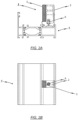
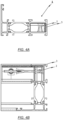
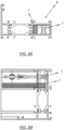
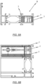
- FIG. 1A
- schematisch und in einer Draufsicht eine erste exemplarische Ausführungsform des erfindungsgemäßen Verbinders, der als Stoßverbinder ausgebildet ist;
- FIG. 1B
- schematisch und in einer Schnittansicht die exemplarische Ausführungsform des erfindungsgemäßen Verbinders gemäß
FIG. 1A ; - FIG. 2A
- schematisch und in einer Draufsicht eine zweite exemplarische Ausführungsform des erfindungsgemäßen Verbinders, der als Stoßverbinder ausgebildet ist;
- FIG. 2B
- schematisch und in einer Schnittansicht die exemplarische Ausführungsform des erfindungsgemäßen Verbinders gemäß
FIG. 2A ; - FIG. 3A
- schematisch und in einer Draufsicht eine dritte exemplarische Ausführungsform des erfindungsgemäßen Verbinders, der als Stoßverbinder ausgeführt ist;
- FIG. 3B
- schematisch und in einer Schnittansicht die exemplarische Ausführungsform des erfindungsgemäßen Verbinders gemäß
FIG. 3A ; - FIG. 4A
- schematisch und in einer Draufsicht eine vierte exemplarische Ausführungsform des erfindungsgemäßen Verbinders, der als Eckverbinder ausgeführt ist;
- FIG. 4B
- schematisch und in einer Querschnittsansicht die exemplarische Ausführungsform des erfindungsgemäßen Verbinders gemäß
FIG. 4A ; - FIG. 5A
- schematisch und in einer Draufsicht eine fünfte exemplarische Ausführungsform des erfindungsgemäßen Verbinders;
- FIG. 5B
- schematisch und in einer Querschnittsansicht die exemplarische Ausführungsform des erfindungsgemäßen Verbinders gemäß
FIG. 5A ; - FIG. 6A
- schematisch und in einer Draufsicht eine sechste exemplarische Ausführungsform des erfindungsgemäßen Verbinders, der als Eckverbinder ausgeführt ist; und
- FIG. 6B
- schematisch und in einer Querschnittsansicht die exemplarische Ausführungsform des erfindungsgemäßen Verbinders gemäß
FIG. 6A . - Zunächst wird unter Bezugnahme auf die Darstellungen in
FIG. 1 bis FIG. 3 eine erste exemplarische Ausführungsvariante einer Profilanordnung in Brandschutzausführung beschrieben. - Die Profilanordnung umfasst im Wesentlichen ein erstes Profil, welches als Anschlussprofil 4 ausgeführt ist, sowie ein zweites Profil, welches als Aufsteckprofil ausgeführt ist. Das Anschlussprofil 4 ist als Innenschale einer wärmegetrennten Profilanordnung ausgeführt, bei welcher das Anschlussprofil 4 über Isolierstege mit einem als Außenschale ausgeführten Profil verbunden ist.
- Das Aufsteckprofil ist ebenfalls als Innenschale einer wärmegetrennten Profilanordnung ausgeführt, bei welcher das Aufsteckprofil über Isolierstege mit einem als Außenschale ausgeführten Profil verbunden ist.
- Bei den Profilen handelt es sich vorzugsweise um längliche Profile, insbesondere Hohlprofile, vorzugsweise aus Aluminium. Das Aufsteckprofil steht vorzugsweise senkrecht auf dem Anschlussprofil 4 und weist zumindest einen Hohlprofilabschnitt bzw. eine Hohlkammer auf.
- Die in
FIG. 1 bis FIG. 3 gezeigte Anordnung weist ferner einen zwischen dem Anschlussprofil 4 und dem Aufsteckprofil angeordneten Stoßverbinder 1 auf. - Bei dem Stoßverbinder 1 handelt es sich um ein Formteil, welches an dem Anschlussprofil 4 befestigt ist, wobei der Stoßverbinder 1 in die Hohlkammer des Aufsteckprofils 5 eingeschoben und an dem Aufsteckprofil befestigt werden kann. In der Regel handelt es sich bei dem Stoßverbinder 1 um ein bearbeitetes stranggepresstes Verbindungselement aus beispielsweise Aluminium mit einem im Wesentlichen rechteckförmigen Querschnitt.
- Wie in
FIG. 1 bis FIG. 3 dargestellt, weist der Stoßverbinder 1 ferner ein Kühlmittel 3 aus einem wärmebindenden Material auf. Das Kühlmittel 3 ist über eine Außen- und/oder Innenseitenfläche eines Verbindungselements 2 des Stoßverbinders 1 mit dem Verbindungselement 2 insbesondere form- und/oder kraftschlüssig verbunden. - Beispielsweise kann das Kühlelement in mindestens eine Nut des Verbindungselements 2 eingeclipst sein.
- Im Einzelnen sind in
FIG. 1A , B bisFIG. 3A , B Ausführungsformen des erfindungsgemäßen Verbinders 1 gezeigt, wobei bei diesen Ausführungsformen der Verbinder 1 als Stoßverbinder 1 zum winkligen Verbinden von jeweils ein Anschlussprofil 4 und ein Aufsteckprofil umfassenden Hohlprofilen ausgeführt ist. - Wie es insbesondere den Querschnittsansichten gemäß
FIG. 1B ,FIG. 2B undFIG. 3B entnommen werden kann, zeichnet sich die exemplarische Ausführungsform des als Stoßverbinder 1 ausgeführten Verbinders dadurch aus, dass der Verbinder 1 ein aus Metall, insbesondere Leichtmetall wie Aluminium, gebildetes Verbindungselement 2 sowie mindestens ein Kühlelement 3 aus einem wärmebindenden Material aufweist. Dabei ist vorgesehen, dass das mindestens eine Kühlelement 3 über mindestens eine Außen- und/oder Innenseitenfläche des Verbindungselements 2 mit dem Verbindungselement 2 insbesondere form- und/oder kraftschlüssig verbunden ist. - Bei den in
FIG. 1 bis FIG. 3 gezeigten exemplarischen Ausführungsformen des erfindungsgemäßen Verbinders 1 ist vorgesehen, dass das Kühlelement 3 als ein die mindestens eine Außenfläche des Verbindungselements 2 zumindest teil- oder bereichsweise abdeckender Formkörper, insbesondere in Gestalt einer Platte, ausgeführt ist. - Das wärmebindende Material des Kühlelements ist insbesondere ein wärmebindendes, hydrophiles Adsorbermaterial mit einem hohen Wasseranteil. Hierbei bietet es sich an, dass das wärmebindende, hydrophile Adsorbermaterial Alaun und vorzugsweise Kalium-Alaun aufweist, welches in einer Gipsmatrix eingebunden sein kann.
- Wie es insbesondere den Querschnittsansichten in
FIG. 1B ,FIG. 2B undFIG. 3B entnommen werden kann, ist der dort als Stoßverbinder 1 ausgeführte Verbinder mit dem bereits genannten Verbindungselement 2 versehen, wobei das Verbindungselement 2 an dem Anschlussprofil 4 mittels Stifte oder Schrauben 6 befestigt ist. Bei aufgesetztem Aufsteckprofil ist dabei das Verbindungselement 2 mit dem mindestens einen Kühlelement 3 in dem als Hohlprofil ausgeführten Aufsteckprofil aufgenommen. - Bei der in
FIG. 1A und FIG. 1B gezeigten Ausführungsform des erfindungsgemä-βen Verbinders 1 ist insbesondere vorgesehen, dass das mindestens eine Kühlelement 3 zumindest teil- und/oder bereichsweise und vorzugsweise vollständig eine insbesondere gemeinsame Außenseitenfläche der beiden Abschnitte des Verbindungselements 2 abdeckt. Allerdings ist die vorliegende Erfindung nicht auf diese Ausgestaltung beschränkt. - Wie es beispielsweise in
FIG. 2A und FIG. 2B angedeutet ist, ist es ebenfalls denkbar, dass das mindestens eine Kühlelement 3 eine Innenseitenfläche des Verbindungselements 2 abdeckt. - Auch ist es - wie in
FIG. 3A und FIG. 3B angedeutet - grundsätzlich denkbar, sowohl auf der Außenseitenfläche als auch auf der Innenseitenfläche des Verbindungselements 2 jeweils ein entsprechendes Kühlelement 3 vorzusehen. - In
FIG. 4 bis FIG. 6 ist schematisch und in einer isometrischen Explosionsansicht eine andere Ausgestaltungsvariante der Profilanordnung in Brandschutzausführung gezeigt. - Bei dieser Ausführungsvariante kommen zwei in einer Gehrungsschnittfläche aufeinanderstoßende Rahmenprofile zum Einsatz, die auf einen als Verbinder 1 ausgeführten Eckwinkel aufgesetzt und mit diesem verbunden sind.
- Auch bei der in
FIG. 4 bis FIG. 6 gezeigten Ausführungsvariante sind die beiden auf Gehrung geschnittenen Hohlprofile jeweils als Innenschale einer wärmegetrennten Profilanordnung ausgeführt, bei welcher das als Innenschale ausgeführte Hohlprofil über Isolierstege mit einem als Außenschale ausgeführten Profil, insbesondere Hohlprofil verbunden ist. - Der als Eckverbinder ausgeführte Verbinder 1 ist wieder mit einem Kühlelement 3 versehen, welches über eine Außen- und/oder Innenseitenfläche des Verbindungselements 2 mit dem Verbindungselement 2 insbesondere form- und/oder kraftschlüssig verbunden ist.
- Im Einzelnen ist in
FIG. 4A , B,FIG. 5A , B undFIG. 6A , B eine alternative Ausführungsvariante des erfindungsgemäßen Verbinders 1 zum Verbinden von Hohlprofilen, insbesondere für Fassaden, Dächer, Fenster oder Türen, dargestellt. Bei dieser Ausführungsvariante ist der Verbinder 1 jedoch nicht als Stoßverbinder, sondern als Eckverbinder zum Verbinden zweier auf Gehrung geschnittener Hohlprofile ausgeführt. - Dabei weist der Verbinder 1 ein aus Metall, insbesondere Leichtmetall wie Aluminium, gebildetes Verbindungselement 2 auf, wobei das Verbindungselement 2 zwei Abschnitte aufweist, die in einem Eckbereich aneinander angrenzen, und wobei der Eckbereich bei dem Verbinden der Hohlprofile im Bereich der Gehrungsfuge angeordnet ist.
- Wie auch bei der zuvor unter Bezugnahme auf die Darstellungen in
FIG. 1 bis FIG. 3 gezeigten Ausführungsvariante des als Stoßverbinder 1 ausgeführten Verbinders 1 ist bei der inFIG. 4 bis FIG. 6 gezeigten Ausführungsform des als Eckverbinder ausgeführten Verbinders 1 vorgesehen, dass das insbesondere aus Aluminium gebildete Verbindungselement 2 des Eckverbinders zusätzlich mit mindestens einem Kühlelement 3 versehen ist. - Bei der in
FIG. 4A , B gezeigten Ausführungsvariante ist das Kühlelement 3 an einer Außenseitenfläche eines Abschnitts des Verbindungselements 2 angeordnet, während bei der inFIG. 5A , B gezeigten Ausführungsvariante das Kühlelement 3 an einer Innenseitenfläche eines Abschnitts des Verbindungselements 2 angeordnet ist. - Bei der in
FIG. 6A , B gezeigten Ausführungsvariante sind entsprechende Kühlelemente sowohl an der Außenseitenfläche als auch an der Innenseitenfläche des Verbindungselements 2 angeordnet. - Die Erfindung ist nicht auf die in den Zeichnungen gezeigten Ausführungsformen beschränkt, sondern ergibt sich aus einer Zusammenschau sämtlicher hierin offenbarter Merkmale.
-
- 1
- Verbinder
- 2
- Verbindungselement
- 3
- Kühlelement
- 4
- Anschlussprofil
- 6
- Stift/Schraube
Claims (15)
- Verbinder (1) zum Verbinden von Hohlprofilen, insbesondere für Fassaden, Dächer, Fenster oder Türen, wobei der Verbinder (1) mindestens ein aus Metall, insbesondere Leichtmetall wie Aluminium, gebildetes Verbindungselement (2) und mindestens ein Kühlelement (3) aus einem wärmebindenden Material aufweist, wobei das mindestens eine Kühlelement (3) unmittelbar benachbart zu einer Seitenfläche des Verbindungselements (2), insbesondere einer Außen- und /oder Innenseitenfläche des Verbindungselements (2), angeordnet ist.
- Verbinder (1) nach Anspruch 1,
wobei das mindestens eine Kühlelement (3) in einem Spaltraum zwischen der Außenseitenfläche des Verbindungselements (2) und einer Innenseitenfläche eines der mit dem Verbinder (1) zu verbindenden Hohlprofilen angeordnet ist. - Verbinder (1) nach Anspruch 2,
wobei das mindestens eine Kühlelement (3) in den Spaltraum zwischen der Außenseitenfläche des Verbindungselements (2) und der Innenseitenfläche des Hohlprofiles eingeschoben ist, insbesondere nach dem Verbinden des Verbindungselements (2) mit dem Hohlprofil. - Verbinder (1) nach Anspruch 1 oder 2,
wobei das mindestens eine Kühlelement (3) über mindestens eine Außenseitenfläche des Verbindungselements (2) mit dem Verbindungselement (2) verbunden, insbesondere form- und/oder kraftschlüssig verbunden ist. - Verbinder (1) nach Anspruch 4,wobei das Kühlelement (3) mindestens eine Materialausformung aufweist, die form- und/oder kraftschlüssig mit mindestens einer zur Materialausformung des Kühlelements (3) zumindest teil- und/oder bereichsweise komplementär ausgeführten Materialausformung des Verbindungselements (2) zusammenwirkt; und/oderwobei das Kühlelement (3) in mindestens eine Nut des Verbindungselements (2) eingeclipst ist.
- Verbinder (1) nach einem der Ansprüche 1 bis 5,
wobei das Kühlelement (3) als ein die mindestens eine Außenseitenfläche des Verbindungselements (2) zumindest teil- oder bereichsweise abdeckender Formkörper, insbesondere in Gestalt einer Platte, ausgeführt ist. - Verbinder (1) nach einem der Ansprüche 1 bis 6,
wobei das wärmebindende Material des Kühlelements (3) ein wärmebindendes, hydrophiles Adsorbermaterial mit hohem Wasseranteil ist. - Verbinder (1) nach Anspruch 7,
wobei das wärmebindende, hydrophile Adsorbermaterial Alaun und vorzugsweise Kalium-Alaun aufweist, welches insbesondere in eine Gipsmatrix eingebunden ist. - Verbinder (1) nach einem der Ansprüche 1 bis 8,
wobei der Verbinder (1) als Stoßverbinder zum winkligen Verbinden von jeweils ein Anschlussprofil (4) und ein Aufsteckprofil umfassenden Hohlprofilen ausgeführt ist, wobei das Verbindungselement (2) an dem Anschlussprofil (4) insbesondere mittels Stifte oder Schrauben (6) befestigt oder befestigbar ist, und wobei bei aufgesetztem Aufsteckprofil das Verbindungselement (2) mit dem mindestens einen Kühlelement (3) in dem als Hohlprofil ausgeführten Aufsteckprofil aufgenommen ist. - Verbinder (1) nach einem der Ansprüche 1 bis 8,
wobei der Verbinder (1) als Eckverbinder zum Verbinden zweier auf Gehrung geschnittener Hohlprofile ausgeführt ist, wobei das Verbindungselement (2) zwei Abschnitte aufweist, die in einem Eckbereich aneinander angrenzen, wobei der Eckbereich bei dem Verbinden der Hohlprofile im Bereich der Gehrungsfuge angeordnet ist. - Verbinder (1) nach Anspruch 10,
wobei das mindestens eine Kühlelement (3) zumindest teil- und/oder bereichsweise und vorzugsweise vollständig eine insbesondere gemeinsame Außenseitenfläche der beiden Abschnitte des Verbindungselements (2) abdeckt. - Anordnung umfassend ein als Hohlprofil ausgeführtes Anschlussprofil (4), ein als Hohlprofil ausgeführtes Aufsteckprofil sowie einen als Stoßverbinder ausgeführten Verbinder (1) nach Anspruch 9, wobei das Anschlussprofil (4) und das Aufsteckprofil miteinander unter Verwendung des Stoßverbinders verbunden sind.
- Anordnung nach Anspruch 12,
wobei das Anschlussprofil (4) als Innenschale einer wärmegetrennten Profilanordnung ausgeführt ist, bei welcher das Anschlussprofil (4) über Isolierstege mit einem als Außenschale ausgeführten Hohlprofil verbunden ist, wobei das mindestens eine Kühlmittel vorzugsweise an einer von dem als Außenschale ausgeführten Hohlprofil wegzeigenden Außenseitenfläche des Stoßverbinders angeordnet ist. - Anordnung umfassend zwei auf Gehrung geschnittene Hohlprofile sowie einen als Eckverbinder ausgeführten Verbinder (1) nach Anspruch 10 oder 11, wobei die beiden auf Gehrung geschnittenen Hohlprofile miteinander unter Verwendung des innerhalb der Hohlprofile aufgenommenen Eckverbinders verbunden sind.
- Anordnung nach Anspruch 14,
wobei die beiden auf Gehrung geschnittenen Hohlprofile jeweils als Innenschale einer wärmegetrennten Profilanordnung ausgeführt sind, bei welcher das als Innenschale ausgeführte Hohlprofil über Isolierstege mit einem als Außenschale ausgeführten Hohlprofil verbunden ist, wobei das mindestens eine Kühlelement (3) vorzugsweise an einer von dem als Außenschale ausgeführten Hohlprofil wegzeigenden Außenseitenfläche des Eckverbinders angeordnet ist.
Priority Applications (1)
| Application Number | Priority Date | Filing Date | Title |
|---|---|---|---|
| EP25188001.9A EP4603670B1 (de) | 2022-11-14 | 2023-11-14 | Verbinder zum verbinden von hohlprofilen |
Applications Claiming Priority (1)
| Application Number | Priority Date | Filing Date | Title |
|---|---|---|---|
| DE102022130070.6A DE102022130070A1 (de) | 2022-11-14 | 2022-11-14 | Verbinder zum verbinden von hohlprofilen |
Related Child Applications (1)
| Application Number | Title | Priority Date | Filing Date |
|---|---|---|---|
| EP25188001.9A Division EP4603670B1 (de) | 2022-11-14 | 2023-11-14 | Verbinder zum verbinden von hohlprofilen |
Publications (3)
| Publication Number | Publication Date |
|---|---|
| EP4368806A1 true EP4368806A1 (de) | 2024-05-15 |
| EP4368806C0 EP4368806C0 (de) | 2025-07-23 |
| EP4368806B1 EP4368806B1 (de) | 2025-07-23 |
Family
ID=88833820
Family Applications (2)
| Application Number | Title | Priority Date | Filing Date |
|---|---|---|---|
| EP23209853.3A Active EP4368806B1 (de) | 2022-11-14 | 2023-11-14 | Verbinder zum verbinden von hohlprofilen |
| EP25188001.9A Active EP4603670B1 (de) | 2022-11-14 | 2023-11-14 | Verbinder zum verbinden von hohlprofilen |
Family Applications After (1)
| Application Number | Title | Priority Date | Filing Date |
|---|---|---|---|
| EP25188001.9A Active EP4603670B1 (de) | 2022-11-14 | 2023-11-14 | Verbinder zum verbinden von hohlprofilen |
Country Status (5)
| Country | Link |
|---|---|
| EP (2) | EP4368806B1 (de) |
| DE (1) | DE102022130070A1 (de) |
| ES (1) | ES3067486T3 (de) |
| HR (1) | HRP20260345T1 (de) |
| PL (1) | PL4603670T3 (de) |
Citations (3)
| Publication number | Priority date | Publication date | Assignee | Title |
|---|---|---|---|---|
| EP0717165B1 (de) * | 1994-12-08 | 1999-05-12 | SCHÜCO International KG | Rahmenwerk aus Metallprofilen in Brandschutzausführung für Fenster, Türen, Fassaden oder Glasdächer |
| EP2154323A2 (de) | 2008-08-08 | 2010-02-17 | Raico Bautechnik GmbH | Eckverbinder zur Verbindung auf Gehrung geschnittener Hohlprofile |
| EP2199524A2 (de) * | 2008-12-18 | 2010-06-23 | Norsk Hydro Asa | Brandschutzelement |
Family Cites Families (2)
| Publication number | Priority date | Publication date | Assignee | Title |
|---|---|---|---|---|
| DE4443761A1 (de) * | 1994-12-08 | 1996-06-13 | Schueco Int Kg | Wärmebindendes Bauteil für den Innen- und Außenausbau in Brandschutzausführung |
| DE10144551A1 (de) * | 2001-09-10 | 2003-03-27 | Bemofensterbau Gmbh | Brandschutzelement, Verfahren zu dessen Herstellung und brandschutzgesichertes Rahmenwerk für ein Gebäudeteil, wie für eine Gebäudefassade oder dgl. |
-
2022
- 2022-11-14 DE DE102022130070.6A patent/DE102022130070A1/de active Pending
-
2023
- 2023-11-14 EP EP23209853.3A patent/EP4368806B1/de active Active
- 2023-11-14 PL PL25188001.9T patent/PL4603670T3/pl unknown
- 2023-11-14 HR HRP20260345TT patent/HRP20260345T1/hr unknown
- 2023-11-14 ES ES25188001T patent/ES3067486T3/es active Active
- 2023-11-14 EP EP25188001.9A patent/EP4603670B1/de active Active
Patent Citations (3)
| Publication number | Priority date | Publication date | Assignee | Title |
|---|---|---|---|---|
| EP0717165B1 (de) * | 1994-12-08 | 1999-05-12 | SCHÜCO International KG | Rahmenwerk aus Metallprofilen in Brandschutzausführung für Fenster, Türen, Fassaden oder Glasdächer |
| EP2154323A2 (de) | 2008-08-08 | 2010-02-17 | Raico Bautechnik GmbH | Eckverbinder zur Verbindung auf Gehrung geschnittener Hohlprofile |
| EP2199524A2 (de) * | 2008-12-18 | 2010-06-23 | Norsk Hydro Asa | Brandschutzelement |
Also Published As
| Publication number | Publication date |
|---|---|
| EP4603670B1 (de) | 2026-01-14 |
| PL4603670T3 (pl) | 2026-05-18 |
| EP4603670A1 (de) | 2025-08-20 |
| EP4368806C0 (de) | 2025-07-23 |
| HRP20260345T1 (hr) | 2026-04-10 |
| EP4368806B1 (de) | 2025-07-23 |
| EP4603670C0 (de) | 2026-01-14 |
| ES3067486T3 (en) | 2026-05-22 |
| DE102022130070A1 (de) | 2024-05-16 |
Similar Documents
| Publication | Publication Date | Title |
|---|---|---|
| EP2786026B1 (de) | Profilstab, profilverbund sowie verfahren zum herstellen eines profilverbundes | |
| EP0717165B1 (de) | Rahmenwerk aus Metallprofilen in Brandschutzausführung für Fenster, Türen, Fassaden oder Glasdächer | |
| DE102019106876A1 (de) | Rahmenprofil eines Blend- und/oder Flügelrahmens, sowie Verfahren zu dessen Herstellung und zur Eckverbindung | |
| EP2048297A2 (de) | Pfosten-Riegel-Fassade in einbruchhemmender AusfUhrung | |
| EP3914799A1 (de) | Profilanordnung | |
| EP1764447A2 (de) | Stossverbinder für Holz-/Aluminiumfassaden | |
| EP3423662B1 (de) | Blendrahmenholm und/oder flügelrahmenholm sowie tür, fenster oder fassadenelement | |
| EP4368806B1 (de) | Verbinder zum verbinden von hohlprofilen | |
| DE102011117170B4 (de) | Wärmegedämmtes Profil | |
| DE102020003776A1 (de) | Anordnung mit einer Befestigungsvorrichtug zur Befestigung einer Absturzsicherung an Hohlkammerprofilen von Fenster- oder Tührrahmen, die in den dafür vorgesehenen Öffnungen einer Gebäudewand eingesetzt sind | |
| EP3889384B1 (de) | Extrudiertes fenster- oder tür-hohlkammerprofil, system mit einem solchen hohlkammerprofil und daraus hergestellter rahmen | |
| DE202012002498U1 (de) | Tür, Metallkonstruktionsprofil einer Zarge oder eines Rahmens für eine Tür oder ein Fenster | |
| DE4107933A1 (de) | Brandschutzkonstruktion fuer ein fassadensystem | |
| DE4404565C1 (de) | Wärmedämmendes Verbundprofil | |
| DE29517375U1 (de) | Verbundprofil | |
| EP4424968B1 (de) | Verbundprofil, rahmen und verfahren zur herstellung des verbundprofils | |
| EP4102019B1 (de) | Fenster- oder tür-hohlkammerprofil, system mit einem solchen hohlkammerprofil und daraus hergestellter rahmen | |
| DE102011008765A1 (de) | Profilanordnung, Rahmen und Rahmenanordnung | |
| EP2708693A1 (de) | Schiebeflügelrahmen | |
| EP3792416B1 (de) | Befestigungsvorrichtung | |
| DE19752619A1 (de) | Verbindungsbauteil für eine Fassadenkonstruktion und Fassadenkonstruktion | |
| DE102008061572A1 (de) | Fensterelement und Verfahren zur Montage | |
| EP4050172A1 (de) | Profilverbinder und unterstruktur für wand- oder dachelemente | |
| EP1932998A1 (de) | Verbundprofil und Verfahren zur Herstellung eines Verbundprofils | |
| DE102020111612B4 (de) | Verbinderanordnung zum winkligen verbinden von jeweils ein anschlussprofil und ein aufschiebprofil umfassenden hohlprofilen sowie einer profilanordnung mit einer solchen verbinderanordnung |
Legal Events
| Date | Code | Title | Description |
|---|---|---|---|
| PUAI | Public reference made under article 153(3) epc to a published international application that has entered the european phase |
Free format text: ORIGINAL CODE: 0009012 |
|
| STAA | Information on the status of an ep patent application or granted ep patent |
Free format text: STATUS: THE APPLICATION HAS BEEN PUBLISHED |
|
| AK | Designated contracting states |
Kind code of ref document: A1 Designated state(s): AL AT BE BG CH CY CZ DE DK EE ES FI FR GB GR HR HU IE IS IT LI LT LU LV MC ME MK MT NL NO PL PT RO RS SE SI SK SM TR |
|
| STAA | Information on the status of an ep patent application or granted ep patent |
Free format text: STATUS: REQUEST FOR EXAMINATION WAS MADE |
|
| 17P | Request for examination filed |
Effective date: 20241103 |
|
| RBV | Designated contracting states (corrected) |
Designated state(s): AL AT BE BG CH CY CZ DE DK EE ES FI FR GB GR HR HU IE IS IT LI LT LU LV MC ME MK MT NL NO PL PT RO RS SE SI SK SM TR |
|
| STAA | Information on the status of an ep patent application or granted ep patent |
Free format text: STATUS: EXAMINATION IS IN PROGRESS |
|
| 17Q | First examination report despatched |
Effective date: 20250124 |
|
| GRAP | Despatch of communication of intention to grant a patent |
Free format text: ORIGINAL CODE: EPIDOSNIGR1 |
|
| STAA | Information on the status of an ep patent application or granted ep patent |
Free format text: STATUS: GRANT OF PATENT IS INTENDED |
|
| INTG | Intention to grant announced |
Effective date: 20250228 |
|
| RAP1 | Party data changed (applicant data changed or rights of an application transferred) |
Owner name: HYDRO BUILDING SYSTEMS LUEDENSCHEID GMBH |
|
| GRAS | Grant fee paid |
Free format text: ORIGINAL CODE: EPIDOSNIGR3 |
|
| GRAA | (expected) grant |
Free format text: ORIGINAL CODE: 0009210 |
|
| STAA | Information on the status of an ep patent application or granted ep patent |
Free format text: STATUS: THE PATENT HAS BEEN GRANTED |
|
| AK | Designated contracting states |
Kind code of ref document: B1 Designated state(s): AL AT BE BG CH CY CZ DE DK EE ES FI FR GB GR HR HU IE IS IT LI LT LU LV MC ME MK MT NL NO PL PT RO RS SE SI SK SM TR |
|
| REG | Reference to a national code |
Ref country code: GB Ref legal event code: FG4D Free format text: NOT ENGLISH |
|
| REG | Reference to a national code |
Ref country code: CH Ref legal event code: EP |
|
| REG | Reference to a national code |
Ref country code: DE Ref legal event code: R096 Ref document number: 502023001414 Country of ref document: DE |
|
| REG | Reference to a national code |
Ref country code: IE Ref legal event code: FG4D Free format text: LANGUAGE OF EP DOCUMENT: GERMAN |
|
| U01 | Request for unitary effect filed |
Effective date: 20250813 |
|
| U07 | Unitary effect registered |
Designated state(s): AT BE BG DE DK EE FI FR IT LT LU LV MT NL PT RO SE SI Effective date: 20250825 |
|
| U20 | Renewal fee for the european patent with unitary effect paid |
Year of fee payment: 3 Effective date: 20251022 |
|
| PG25 | Lapsed in a contracting state [announced via postgrant information from national office to epo] |
Ref country code: IS Free format text: LAPSE BECAUSE OF FAILURE TO SUBMIT A TRANSLATION OF THE DESCRIPTION OR TO PAY THE FEE WITHIN THE PRESCRIBED TIME-LIMIT Effective date: 20251123 |
|
| PG25 | Lapsed in a contracting state [announced via postgrant information from national office to epo] |
Ref country code: NO Free format text: LAPSE BECAUSE OF FAILURE TO SUBMIT A TRANSLATION OF THE DESCRIPTION OR TO PAY THE FEE WITHIN THE PRESCRIBED TIME-LIMIT Effective date: 20251023 |
|
| PG25 | Lapsed in a contracting state [announced via postgrant information from national office to epo] |
Ref country code: HR Free format text: LAPSE BECAUSE OF FAILURE TO SUBMIT A TRANSLATION OF THE DESCRIPTION OR TO PAY THE FEE WITHIN THE PRESCRIBED TIME-LIMIT Effective date: 20250723 |
|
| PG25 | Lapsed in a contracting state [announced via postgrant information from national office to epo] |
Ref country code: GR Free format text: LAPSE BECAUSE OF FAILURE TO SUBMIT A TRANSLATION OF THE DESCRIPTION OR TO PAY THE FEE WITHIN THE PRESCRIBED TIME-LIMIT Effective date: 20251024 |
|
| PG25 | Lapsed in a contracting state [announced via postgrant information from national office to epo] |
Ref country code: PL Free format text: LAPSE BECAUSE OF FAILURE TO SUBMIT A TRANSLATION OF THE DESCRIPTION OR TO PAY THE FEE WITHIN THE PRESCRIBED TIME-LIMIT Effective date: 20250723 |
|
| PG25 | Lapsed in a contracting state [announced via postgrant information from national office to epo] |
Ref country code: RS Free format text: LAPSE BECAUSE OF FAILURE TO SUBMIT A TRANSLATION OF THE DESCRIPTION OR TO PAY THE FEE WITHIN THE PRESCRIBED TIME-LIMIT Effective date: 20251023 |
|
| PG25 | Lapsed in a contracting state [announced via postgrant information from national office to epo] |
Ref country code: ES Free format text: LAPSE BECAUSE OF FAILURE TO SUBMIT A TRANSLATION OF THE DESCRIPTION OR TO PAY THE FEE WITHIN THE PRESCRIBED TIME-LIMIT Effective date: 20250723 |
|
| PG25 | Lapsed in a contracting state [announced via postgrant information from national office to epo] |
Ref country code: SM Free format text: LAPSE BECAUSE OF FAILURE TO SUBMIT A TRANSLATION OF THE DESCRIPTION OR TO PAY THE FEE WITHIN THE PRESCRIBED TIME-LIMIT Effective date: 20250723 |
|
| PG25 | Lapsed in a contracting state [announced via postgrant information from national office to epo] |
Ref country code: CZ Free format text: LAPSE BECAUSE OF FAILURE TO SUBMIT A TRANSLATION OF THE DESCRIPTION OR TO PAY THE FEE WITHIN THE PRESCRIBED TIME-LIMIT Effective date: 20250723 |
|
| PG25 | Lapsed in a contracting state [announced via postgrant information from national office to epo] |
Ref country code: SK Free format text: LAPSE BECAUSE OF FAILURE TO SUBMIT A TRANSLATION OF THE DESCRIPTION OR TO PAY THE FEE WITHIN THE PRESCRIBED TIME-LIMIT Effective date: 20250723 |
|
| PLBI | Opposition filed |
Free format text: ORIGINAL CODE: 0009260 |
|
| REG | Reference to a national code |
Ref country code: CH Ref legal event code: L10 Free format text: ST27 STATUS EVENT CODE: U-0-0-L10-L00 (AS PROVIDED BY THE NATIONAL OFFICE) Effective date: 20260507 |
|
| PLAX | Notice of opposition and request to file observation + time limit sent |
Free format text: ORIGINAL CODE: EPIDOSNOBS2 |
|
| 26 | Opposition filed |
Opponent name: REYNAERS ALUMINIUM NV Effective date: 20260423 |
|
| PG25 | Lapsed in a contracting state [announced via postgrant information from national office to epo] |
Ref country code: MC Free format text: LAPSE BECAUSE OF FAILURE TO SUBMIT A TRANSLATION OF THE DESCRIPTION OR TO PAY THE FEE WITHIN THE PRESCRIBED TIME-LIMIT Effective date: 20250723 |
|
| PLBB | Reply of patent proprietor to notice(s) of opposition received |
Free format text: ORIGINAL CODE: EPIDOSNOBS3 |