EP4370423B1 - Vorrichtung zur steuerung der winkelgeschwindigkeit eines raumfahrzeugs und zugehöriges raumfahrzeug - Google Patents
Vorrichtung zur steuerung der winkelgeschwindigkeit eines raumfahrzeugs und zugehöriges raumfahrzeug Download PDFInfo
- Publication number
- EP4370423B1 EP4370423B1 EP22789648.7A EP22789648A EP4370423B1 EP 4370423 B1 EP4370423 B1 EP 4370423B1 EP 22789648 A EP22789648 A EP 22789648A EP 4370423 B1 EP4370423 B1 EP 4370423B1
- Authority
- EP
- European Patent Office
- Prior art keywords
- rotor
- stator
- spacecraft
- control device
- angular
- Prior art date
- Legal status (The legal status is an assumption and is not a legal conclusion. Google has not performed a legal analysis and makes no representation as to the accuracy of the status listed.)
- Active
Links
Images


Classifications
-
- B—PERFORMING OPERATIONS; TRANSPORTING
- B64—AIRCRAFT; AVIATION; COSMONAUTICS
- B64G—COSMONAUTICS; VEHICLES OR EQUIPMENT THEREFOR
- B64G1/00—Cosmonautic vehicles
- B64G1/22—Parts of, or equipment specially adapted for fitting in or to, cosmonautic vehicles
- B64G1/24—Guiding or controlling apparatus, e.g. for attitude control
- B64G1/32—Guiding or controlling apparatus, e.g. for attitude control using earth's magnetic field
-
- B—PERFORMING OPERATIONS; TRANSPORTING
- B64—AIRCRAFT; AVIATION; COSMONAUTICS
- B64G—COSMONAUTICS; VEHICLES OR EQUIPMENT THEREFOR
- B64G1/00—Cosmonautic vehicles
- B64G1/22—Parts of, or equipment specially adapted for fitting in or to, cosmonautic vehicles
- B64G1/24—Guiding or controlling apparatus, e.g. for attitude control
- B64G1/244—Spacecraft control systems
Definitions
- the field of the invention is that of attitude control of spacecraft, such as satellites.
- the invention relates more particularly to a device for controlling the angular velocity of a decommissioned spacecraft.
- the invention thus has applications, in particular, but not exclusively, for all spacecraft for which an end-of-life removal operation must be considered.
- spacecraft in order to capture and deorbit space debris such as a decommissioned satellite, spacecraft are known that are capable of performing maneuvers such as docking with the debris, so as to form a composite, such as for example deorbiting satellites such as those described in the applications EP2746163 And EP2671804 . It is nevertheless understood that the rotation speed of the out-of-service satellite remains a limiting factor in the success of the capture phase for such missions. It is indeed common for an out-of-service satellite to have a high angular speed, either because of a fatal failure that has also interrupted the mission (propulsion failure, collision with debris), or because of the accumulation of low external disturbances (solar radiation pressure) over long periods.
- the immediate follow-up operations for the control of the composite are incompatible with a high rotation speed, in particular when the out-of-service satellite is connected to the deorbiting satellite by flexible links, such as a harpoon or a net.
- the invention relates to a device for controlling the angular velocity of a decommissioned spacecraft for facilitating active removal operations of the spacecraft as space debris.
- Such an angular velocity control device comprises a stator and a rotor movable along an axis of rotation relative to the stator, the stator being intended to be driven by the spacecraft to be stabilized, the rotor being intended to orient itself according to the Earth's magnetic field.
- the stator comprises an electrically conductive and non-ferromagnetic body while the rotor comprises a magnetized system configured to induce, in the stator, eddy currents for braking a relative movement of the rotor relative to the stator.
- the invention proposes a novel and inventive solution for controlling the attitude of a decommissioned spacecraft (i.e. on board of which no energy source is available).
- This aim is achieved by a passive magnetic damping device fixed to the structure of the platform, where a rotor equipped with magnets is free to rotate inside a non-ferromagnetic conductive stator (i.e. so as not to become magnetized over time).
- the magnets of the magnetized system are placed opposite the body, for example made of aluminum.
- the rotor Even if the spacecraft pivots, the rotor remains aligned with the geomagnetic field: the differential angular velocity between the rotor and the platform creates eddy currents in the stator and thus dissipates the rotational kinetic energy, tending to stop the rotation of the spacecraft relative to the Earth's magnetic field.
- the rotor is guided in at least one housing of the stator, the rotor comprising at least one magnet cooperating with at least one countermagnet disposed in said housing of the stator, so as to induce magnetic levitation of the rotor relative to the stator when the attitude control device is in microgravity and also when the attitude control device is in Earth gravity.
- Two magnets and countermagnets act for example in two opposite directions and along the axis of rotation of the rotor.
- the angular velocity control device comprises means for maintaining the distance between respective magnetized zones of the stator and the rotor, the means for maintaining the distance being arranged to resist forces during take-off and release.
- the corresponding magnets and countermagnets do not have to support the weight of the rotor, e.g. in the presence of gravity or during accelerations (e.g. during the launch of a satellite comprising such a device).
- the distance-keeping means comprise at least one rotor ring and a stator shoulder.
- the ring is intended to cooperate with the shoulder arranged at a distance and facing the ring in an axial direction and in a radial direction.
- the ring can abut against the shoulder, for example during acceleration, thus ensuring distance-keeping.
- the shoulder is arranged so as to guarantee a minimum distance between the respective magnetized zones of the stator and the rotor.
- the rotor comprises parts constituting a pivot axis and a flexible diaphragm.
- the rotor ring is mechanically connected to the pivot axis by the diaphragm.
- the ring can carry the magnetized system, while the pivot axis carries the pair or pairs of magnets and countermagnets.
- a satellite may for example comprise magnets for braking, magnets for orientation relative to the Earth's magnetic field and magnets and countermagnets for lifting the rotor axis.
- the pivot axis does not have to support the mechanical stress to block a tilting movement of the pivot axis relative to the axis of rotation.
- the magnet system includes a plurality of braking magnets arranged in a plane perpendicular to the axis of rotation of the rotor.
- the magnetic moments of the braking magnets sum according to a non-zero component in the plane perpendicular to the axis of rotation of the rotor so that the braking magnets also allow orientation of the rotor according to the Earth's magnetic field.
- Such a configuration makes it possible to combine the compass function and the current induction function.
- the magnetic moments of several of the braking magnets are substantially perpendicular to the plane perpendicular to the axis of rotation of the rotor, such that their magnetic field passes through the plane perpendicular to the axis of rotation of the rotor to induce eddy currents in at least two regions of the stator body located opposite each other on either side of the plane perpendicular to the axis of rotation of the rotor.
- the stator has a U-shaped profile extending around and on either side of the ring.
- the amount of currents induced by a rotor magnet is doubled compared to an implementation in which the magnetic moment of the magnet is substantially parallel to the rotor's plane of rotation (i.e. perpendicular to the rotor's axis of rotation).
- the magnetic moments of several of the braking magnets form an oblique angle with respect to said plane perpendicular to the axis of rotation of the rotor.
- Such a configuration makes it possible to combine the compass function and the doubling of induced currents.
- the invention also relates to a spacecraft comprising one or more angular rate control devices as described above (according to any of the aforementioned embodiments).
- the spacecraft further comprises three-axis attitude control means adapted to stabilize the attitude of the spacecraft in operation.
- the angular velocity control device(s) of the spacecraft when it is out of service act simultaneously with the attitude control means of the spacecraft in operation and exert a negligible action relative to these attitude control means of the spacecraft in operation.
- each angular rate control device is arranged so that the axis of rotation of the rotor forms an angle less than or equal to 45° with an axis of greatest inertia of the spacecraft, such that the spacecraft out of service tends towards a rotational movement around this axis of greatest inertia.
- a first advantage of the invention is to allow the reduction of the angular speed of the satellite to be captured, prior to its capture which is thus facilitated.
- the present invention thus makes it possible to avoid an out-of-service satellite being driven by a high angular speed, either because of a fatal failure having caused the interruption of the mission such as a propulsion failure, or a collision with debris, or because of the accumulation of weak external disturbances caused for example by solar radiation pressure, over long periods.
- the general principle of the invention is based on a device for controlling the angular speed of a spacecraft, in particular making it possible to facilitate the operations of removing the spacecraft as space debris.
- a device for controlling the angular speed of a spacecraft, in particular making it possible to facilitate the operations of removing the spacecraft as space debris.
- Such a device comprises a stator and a rotor movable along an axis of rotation relative to the stator, the stator being intended to be driven by the spacecraft to be stabilized, the rotor being intended to orient itself according to the Earth's magnetic field.
- the stator comprises an electrically conductive and non-ferromagnetic body while the rotor comprises a magnetized system configured to induce, in the stator, eddy currents for braking a relative movement of the rotor relative to the stator.
- the rotor behaves like a compass needle thanks to a magnetic moment bias provided by an asymmetric arrangement of the polarities of the braking magnets or thanks to dedicated orientation magnets.
- the rotor remains aligned with the Earth's magnetic field (compass function).
- the differential angular velocity between the rotor and the spacecraft creates eddy currents in the stator and thus dissipates the rotational kinetic energy, tending to stop the rotational motion of the spacecraft relative to the Earth's magnetic field.
- the rotational speed of the spacecraft is thus controlled.
- the device 1 makes it possible in particular to control the angular velocity of the spacecraft 2 when the latter is out of service. This makes it possible, for example, to facilitate the operations of active removal of the spacecraft 2 as space debris.
- the device 1 comprises a stator 3 and a rotor 4 movable along an axis A21 of rotation of the rotor 4 relative to the stator 3.
- the stator is for example integral with the frame of the satellite.
- the stator 3 is intended to be driven by the spacecraft 2 to be stabilized.
- the rotor 4 is intended to orient itself according to the Earth's magnetic field.
- stator 3 comprises an electrically conductive body 6, for example made of aluminum, while the rotor 4 comprises a magnetic system 7 configured to induce, in the stator 3, eddy currents for braking a relative movement of the rotor 4 with respect to the stator 3.
- the body 6 of the stator 3 is electrically conductive and non-ferromagnetic so as not to become magnetized over time.
- the body 6 is for example made of aluminum or copper.
- the magnetic system 7 comprises, on the one hand, braking magnets 18 and, on the other hand, orientation magnets 19.
- the braking magnets 18 are configured to induce, in the stator 3, the braking eddy currents of the relative movement of the rotor 4 with respect to the stator 3.
- the orientation magnets 19 are configured to maintain the orientation of the rotor 4 with respect to the Earth's magnetic field 5 (compass function).
- the magnetic system 7 comprises a plurality of braking magnets 18a, 18b, 18c, 18d arranged along a plane P20 perpendicular to the axis A21 of rotation of the rotor 4 relative to the stator 3.
- the magnetic moments M22a and M22b of the braking magnets 18a and 18b sum according to a non-zero component in the plane P20 so that the braking magnets 18a and 18b also allow an orientation of the rotor 4 according to the Earth's magnetic field 5.
- the braking magnets 18 fulfill the function of the orientation magnets 19 (compass function).
- the braking magnets 18 and the orientation magnets 19 are here the same magnets.
- the magnetic moments M22 of several braking magnets 18 are here substantially parallel to the plane P20 perpendicular to the axis A21 of rotation of the rotor 4.
- the same braking magnets 18 can be used to also provide the function of orienting the rotor 4 relative to the stator 3 as described above in relation to the [ Fig.2 ].
- the braking magnets 18 it is also easier to control the size of the air gap between the magnets 18 and the body 6 of the stator 3 (e.g. to address the problem of launching vibrations, of free play in the pivot of the rotor 4) or to accommodate magnets 18 with a larger aspect ratio (e.g. a greater height of the magnets 18 allows a larger air gap).
- the housing of the stator 3 may be made of any material, for example plastic, with simply a track 6 made of non-ferromagnetic material (e.g. aluminum or copper) forming a housing or arranged in a housing made in the stator 3, opposite the magnets 18.
- This housing extends for example around the stator with a U-shaped profile.
- the stator comprises for example a cylindrical ring coming into this housing.
- the magnetic moments M22 of several braking magnets 18 are here substantially perpendicular to the plane P20.
- the magnetic moments M22 of the braking magnets 18 in question are here substantially parallel to the axis A21 of rotation of the rotor 4.
- the magnetic field of the braking magnets 18 crosses the plane P20 to induce eddy currents in at least two zones of the body 6 of the stator 3 located opposite each other on either side of the plane P20 in question.
- the eddy currents thus induced are potentially doubled compared to a radial configuration of the braking magnets 18 as described above in relation to the [ Fig.3a ].
- the braking magnets 18 cannot at the same time fulfil the function of orienting the rotor 4 relative to the stator 3. Additional magnets fulfilling the function of orienting the rotor 4 relative to the stator 3 are necessary here, for example orientation magnets 19 as described above in connection with the [ Fig.1 ].
- the additional magnets fulfilling the function of orienting the rotor 4 relative to the stator 3 are other braking magnets 18 in radial configuration as described above in relation to the [ Fig.3a ]. We thus obtain a mixed configuration with some 18 brake magnets in normal configuration and some 18 brake magnets in radial configuration.
- the magnetic moments M22 of several braking magnets 18 form an oblique angle with respect to the plane P20 perpendicular to the axis A21 of rotation of the rotor 4.
- the magnetic moments M22 in question form an angle with the axis A21 of rotation of the rotor 4 of between 10 degrees and 80 degrees, preferably between 30 degrees and 60 degrees.
- eddy currents are also induced on either side of the plane P20 in question.
- a non-zero component of the total magnetic moment of the braking magnets 18 can thus be obtained in the plane P20 in question.
- the braking magnets 18 also provide the function of orienting the rotor 4 relative to the stator 3 (compass function).
- the rotor 4 In practice, the rotor 4 must be adjusted to the stator 3 with sufficient precision so that the braking magnets 18 typically move within 1 mm of the body 6 of the stator 3 without ever touching each other. Furthermore, the means for adjusting the rotor 4 to the stator 3 must induce as little friction as possible, so that the rotor 4 is always free to rotate. The friction must be a fraction of the magnetic torque driving the rotor 4. This is not necessarily a problem for conditions in orbit, when the forces and torques acting on the rotor 4 are small. But it may be a problem during ground tests, in order to allow testing of the device 1 before placing in orbit.
- the rotor 4 is here guided in a corresponding housing 10a, 10b of the stator 3.
- it is the two ends of a pivot axis 4 of the rotor 4 which are guided in a corresponding housing 10a, 10b of the stator 3.
- the rotor 4 does not comprise a pivot axis 4 as such.
- it is for example ball joints arranged along the axis A21 of rotation and intended to be guided each with a corresponding housing of the stator 3.
- each end of the pivot axis 8 comprises one (or more) magnets 11a, 11b cooperating with one (or more) counter-magnets 12a, 12b arranged in the corresponding housing 10a, 10b of the stator 3.
- a magnetic levitation of the rotor 4 relative to the stator 3 is induced when the attitude control device 1 is in microgravity, but also when the attitude control device 1 is in Earth gravity.
- the testing of the device 1 on the ground is possible.
- the permitted range of motion along the rotation axis A21 for the rotor 4 is such that, on Earth (i.e. under 1 g) and when the device is arranged so that the axis A21 is vertical, the magnetic suspension of the rotor 4 relative to the stator 3 linked to the magnet pair 11a, 11b / countermagnet 12a, 12b located in the upper part of the device 1 has a negligible effect on the pivot axis 8.
- in orbit i.e.
- the two suspensions linked to the two magnet pairs 11a, 11b / countermagnet 12a, 12b have a negligible effect on the pivot axis 8 when the latter is halfway through its permitted range of translational motion along the axis A21, which makes the friction even lower.
- the rotor 4 and the stator 3 are not equipped with such magnet 11a, 11b / countermagnet 12a pairs.
- the friction is for example reduced via mechanical means such as ball bearings or friction-reducing materials.
- the angular rate control device 1 must withstand the launch loads without any clamping mechanism, the rotor 4 being free to move at all times. However, in order to minimize friction, a non-zero mechanical tolerance is necessary between the rotor 4 and the stator 3. Potentially, there may be mechanical play between the rotor 4 and the stator 3 when the rotor 4 reaches the ends of its permitted range of motion in translation and rotation.
- the pivot axis 8 and the magnet 11a, 11b / countermagnet 12a, 12b pairs are not necessarily designed to support the weight of the rotor 4 or the shocks.
- the angular speed control device 1 here comprises means for maintaining the distance between the respective magnetized zones of the stator 3 and the rotor 4, i.e. the zones in which the magnet 11a, 11b / countermagnet 12a, 12b pairs are implemented.
- the distance maintaining means in question are arranged to withstand forces both during take-off and release, and this for the 3 possible translations between the rotor 4 and the stator 3 (the 3 translations in question are indicated by the dotted arrows on the [ Fig.4a], [Fig.4b] and [Fig.4c] ]).
- the distance-keeping means comprise a ring 15 of the rotor 4 and a shoulder 16 of the stator 3.
- the ring 15 is intended to cooperate with the shoulder 16 arranged at a distance and facing the ring 15 in an axial direction and in a radial direction.
- the shoulder 16 is arranged so as to guarantee a minimum distance between the respective magnetized zones of the stator 3 and the rotor 4.
- rings are implemented on the rotor 4.
- the rings in question are configured to cooperate with corresponding shoulders of the stator 3.
- the ring(s) may be implemented on the stator 3 and the corresponding shoulder(s) are implemented on the rotor 4.
- the rotor 4 is prevented from touching the stator 3 while ensuring that the pivot axis 8 does not have to withstand the mechanical stress making it possible to block the tilting movement in question.
- such a model makes it possible to estimate the derotation time constant of a spacecraft to which an angular velocity control device according to the present technique would be attached.
- a braking magnet 18 with a length b sufficiently large compared to its width a that it can be considered infinite.
- the braking magnet 18 is housed radially at the periphery of a cylindrical rotor 4 of infinite length along its axis (y axis) and radius R .
- stator 3 of each device 1 is fixed to the spacecraft 2 so as to be driven by the spacecraft 2.
- the rotor 4 of each device 1 is oriented according to the Earth's magnetic field 5.
- two angular velocity control devices 1 are implemented in the spacecraft 2 to be stabilized when it is out of service.
- a device 1 of angular rate control according to the present technique cannot theoretically damp angular velocities normal to its axis.
- an out-of-service spacecraft 2 will naturally tend to follow a rotational motion about its main axis of maximum inertia.
- an angular rate control device 1 is not implanted so as to have its axis A21 of rotation strictly perpendicular to the main axis of maximum inertia, one can expect to observe residual angular rotation rates.
- a single angular rate control device 1 is sufficient in theory to dampen the rotation of the spacecraft 2 around the 3 axes of inertia, it may be interesting in practice to implement two or three angular rate control devices 1 for redundancy purposes.
- the spacecraft 2 is equipped with a single angular velocity control device 1.
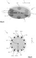
- the axis A21 of rotation of the rotor 4 of the angular speed control device(s) 1 forms an angle less than or equal to 45° with the axis of greatest inertia of the spacecraft 2 (axis denoted “ I max ” in the [ Fig.7 ]), such that the out-of-service spacecraft 2 tends towards a rotational movement around this axis of greatest inertia. Indeed, the rotation of the spacecraft 2 will naturally tend towards a rotation around its axis of greatest inertia (a phenomenon known as "flat spin" according to English terminology).
- an arrangement according to which the axis(es) A21 of rotation of the rotor(s) 4 of the angular speed control device(s) 1 form an angle less than or equal to 45° with the axis of greatest inertia of the spacecraft 2 makes it possible to guarantee dissipation of the rotational kinetic energy of the spacecraft 2 around its axis of greatest inertia, resulting in slowing down the rotation of the spacecraft.
- the active spacecraft 2 further comprises attitude control means along three axes adapted to stabilize the attitude of the active spacecraft.
- the angular velocity control device(s) 1 act simultaneously with the attitude control means of the active spacecraft but exert a negligible action compared to these attitude control means of the active spacecraft.
- the angular velocity control device(s) 1 have a negligible effect on the attitude control of the spacecraft 2 when the latter is in operation, but make it possible to control the angular velocity of the spacecraft 2 when the latter is out of service.
Landscapes
- Engineering & Computer Science (AREA)
- Remote Sensing (AREA)
- Chemical & Material Sciences (AREA)
- Combustion & Propulsion (AREA)
- Radar, Positioning & Navigation (AREA)
- Aviation & Aerospace Engineering (AREA)
- General Life Sciences & Earth Sciences (AREA)
- Geochemistry & Mineralogy (AREA)
- Geology (AREA)
- Environmental & Geological Engineering (AREA)
- Life Sciences & Earth Sciences (AREA)
- Automation & Control Theory (AREA)
- Control Of Position, Course, Altitude, Or Attitude Of Moving Bodies (AREA)
- Connection Of Motors, Electrical Generators, Mechanical Devices, And The Like (AREA)
Claims (12)
- Gerät (1) zur Kontrolle der Winkelgeschwindigkeit eines außer Dienst gestellten Raumfahrzeugs (2), das es ermöglicht, die Operationen zur aktiven Entfernung des Raumfahrzeugs als Weltraumschrott zu erleichtern, umfassend einen Stator (3) und einen Rotor (4), der entlang einer Drehachse (A21) in Bezug auf den Stator beweglich ist, wobei der Stator (3) dazu bestimmt ist, von dem zu stabilisierenden Raumfahrzeug (2) angetrieben zu werden, wobei der Rotor (4) dazu bestimmt ist, sich gemäß dem Erdmagnetfeld (5) auszurichten, wobei der Stator (3) einen elektrisch leitenden und nicht ferromagnetischen Körper (6) umfasst, während der Rotor (4) ein Magnetsystem (7) umfasst, das konfiguriert ist, um im Stator (3) Wirbelströme zum Bremsen einer Relativbewegung des Rotors (4) in Bezug auf den Stator (3) zu induzieren.
- Gerät (1) zur Kontrolle der Winkelgeschwindigkeit nach Anspruch 1, wobei der Rotor (4) in mindestens einer Aufnahme (10a, 10b) des Stators (3) geführt wird, wobei der Rotor mindestens einen Magneten (11a, 11b) umfasst, der mit mindestens einem Gegenmagneten (12a, 12b) zusammenwirkt, der in der Aufnahme des Stators angeordnet ist, sodass ein magnetischer Auftrieb des Rotors (4) in Bezug auf den Stator (3) induziert wird, wenn sich das Gerät (1) zur Lagekontrolle in der Mikrogravitation befindet, und auch, wenn sich das Gerät (1) zur Lagekontrolle in der Erdgravitation befindet.
- Gerät (1) zur Kontrolle der Winkelgeschwindigkeit nach Anspruch 1 oder 2, umfassend Mittel zum Fernhalten von jeweiligen magnetisierten Zonen des Stators und des Rotors, wobei die Mittel zum Fernhalten so angeordnet sind, dass sie Belastungen beim Start und beim Abwurf standhalten.
- Gerät (1) zur Kontrolle der Winkelgeschwindigkeit nach Anspruch 3, wobei die Mittel zum Fernhalten mindestens einen Ring (15) des Rotors und eine Schulter (16) des Stators (3) umfassen, wobei der Ring dazu bestimmt ist, mit der Schulter (16) zusammenzuwirken, die in einem Abstand und gegenüber dem Ring (15) in einer axialen Richtung und in einer radialen Richtung angeordnet ist, wobei die Schulter (16) so angeordnet ist, dass sie einen Mindestabstand zwischen den jeweiligen magnetisierten Zonen des Stators und des Rotors gewährleistet.
- Gerät (1) zur Kontrolle der Winkelgeschwindigkeit nach Anspruch 4, wobei der Rotor Teile umfasst, die eine Schwenkachse (8) und eine flexible Blende (17) bilden, wobei der Ring (15) des Rotors durch die Blende (17) mechanisch mit der Schwenkachse (8) verbunden ist.
- Gerät (1) zur Kontrolle der Winkelgeschwindigkeit nach einem der Ansprüche 1 bis 5, wobei das Magnetsystem eine Vielzahl von Magneten (18a, 18b, 18c, 18d) zur Bremsung umfasst, die in einer Ebene (P20) angeordnet sind, die senkrecht zur Drehachse (A21) des Rotors verläuft.
- Gerät (1) zur Kontrolle der Winkelgeschwindigkeit nach Anspruch 6, wobei die magnetischen Momente (M22a, M22b) der Bremsmagnete in der Ebene senkrecht zur Drehachse des Rotors mit einer von Null verschiedenen Komponente aufgehen, sodass die Bremsmagnete auch eine Ausrichtung des Rotors gemäß dem Erdmagnetfeld ermöglichen.
- Gerät (1) zur Kontrolle der Winkelgeschwindigkeit nach Anspruch 6 oder 7, wobei die magnetischen Momente mehrerer der Bremsmagnete im Wesentlichen senkrecht zu der Ebene senkrecht zur Drehachse des Rotors sind, sodass ihr Magnetfeld die Ebene senkrecht zur Drehachse des Rotors durchquert, um Wirbelströme in mindestens zwei Zonen des Statorkörpers zu induzieren, die sich auf beiden Seiten der Ebene senkrecht zur Drehachse des Rotors gegenüberliegen.
- Gerät (1) zur Kontrolle der Winkelgeschwindigkeit nach einem der Ansprüche 6 bis 8, wobei die magnetischen Momente mehrerer der Bremsmagnete einen schiefen Winkel in Bezug auf die Ebene bilden, die senkrecht zur Drehachse des Rotors verläuft.
- Raumfahrzeug (2), umfassend mindestens ein Gerät (1) zur Kontrolle der Winkelgeschwindigkeit nach einem der Ansprüche 1 bis 9.
- Raumfahrzeug (2) nach dem vorstehenden Anspruch, ferner umfassend Mittel zur Lagekontrolle in drei Achsen, die geeignet sind, die Lage des aktiven Raumfahrzeugs zu stabilisieren, wobei das Gerät (1) zur Kontrolle der Winkelgeschwindigkeit gleichzeitig mit den Mitteln zur Lagekontrolle des aktiven Raumfahrzeugs wirkt und eine vernachlässigbare Wirkung in Bezug auf diese Mittel zur Lagekontrolle des aktiven Raumfahrzeugs ausübt.
- Raumfahrzeug (2) nach Anspruch 10 oder 11, wobei das Gerät (1) zur Kontrolle der Winkelgeschwindigkeit so angeordnet ist, dass die Drehachse des Rotors einen Winkel von 45° oder weniger mit einer Achse der größten Trägheit des Raumfahrzeugs bildet, sodass das außer Betrieb befindliche Raumfahrzeug zu einer Drehbewegung um diese Achse der größten Trägheit tendiert.
Applications Claiming Priority (2)
| Application Number | Priority Date | Filing Date | Title |
|---|---|---|---|
| FR2110081A FR3127481B1 (fr) | 2021-09-24 | 2021-09-24 | Dispositif de contrôle de vitesse angulaire d’un engin spatial et engin spatial correspondant. |
| PCT/FR2022/051767 WO2023047049A1 (fr) | 2021-09-24 | 2022-09-20 | Dispositif de contrôle de vitesse angulaire d'un engin spatial et engin spatial correspondant |
Publications (3)
| Publication Number | Publication Date |
|---|---|
| EP4370423A1 EP4370423A1 (de) | 2024-05-22 |
| EP4370423B1 true EP4370423B1 (de) | 2025-01-22 |
| EP4370423C0 EP4370423C0 (de) | 2025-01-22 |
Family
ID=79831559
Family Applications (1)
| Application Number | Title | Priority Date | Filing Date |
|---|---|---|---|
| EP22789648.7A Active EP4370423B1 (de) | 2021-09-24 | 2022-09-20 | Vorrichtung zur steuerung der winkelgeschwindigkeit eines raumfahrzeugs und zugehöriges raumfahrzeug |
Country Status (5)
| Country | Link |
|---|---|
| US (1) | US20240400233A1 (de) |
| EP (1) | EP4370423B1 (de) |
| ES (1) | ES3025154T3 (de) |
| FR (1) | FR3127481B1 (de) |
| WO (1) | WO2023047049A1 (de) |
Families Citing this family (2)
| Publication number | Priority date | Publication date | Assignee | Title |
|---|---|---|---|---|
| KR102445902B1 (ko) * | 2022-05-23 | 2022-09-21 | 한국해양과학기술원 | 자기부상 로터세일 |
| FR3146660B1 (fr) * | 2023-03-13 | 2026-02-20 | Airbus Defence & Space Sas | Dispositif de contrôle de vitesse angulaire d'un engin spatial et engin spatial correspondant. |
Family Cites Families (10)
| Publication number | Priority date | Publication date | Assignee | Title |
|---|---|---|---|---|
| US3526795A (en) * | 1966-06-20 | 1970-09-01 | William Pecs | Torque reaction attitude control device |
| GB1544083A (en) * | 1975-07-21 | 1979-04-11 | Rca Corp | Precision closed loop roll and yaw control for momentum biased satellites in low inclination orbits |
| JPS58149899A (ja) * | 1982-02-26 | 1983-09-06 | 三菱電機株式会社 | 人口衛星姿勢制御用磁気軸受ホイ−ル |
| US6191513B1 (en) * | 1997-10-27 | 2001-02-20 | Mohawk Innovative Technology, Inc. | Stator-controlled magnetic bearing |
| AU5021999A (en) * | 1998-07-23 | 2000-02-14 | Bristol Aerospace Limited | System and method for spacecraft attitude control |
| EP2671804B1 (de) | 2012-06-07 | 2014-04-30 | Astrium Limited | Einfangen von Raumobjekten |
| FR2999537B1 (fr) | 2012-12-19 | 2015-02-20 | Astrium Sas | Systeme et procede de capture et d'elimination d'un debris spatial |
| FR3058393A1 (fr) | 2016-11-10 | 2018-05-11 | Airbus Defence And Space Sas | Engin spatial comprenant des moyens de controle actif d’attitude et des moyens de controle passif d’attitude |
| DE102017102481A1 (de) * | 2017-02-08 | 2018-08-09 | Klaus Schilling | Formationsfähiger Kleinstsatellit und Formation aus mehreren Kleinstsatelliten |
| US11124320B2 (en) * | 2019-02-12 | 2021-09-21 | Canadian Space Agency | Spacecraft control using residual dipole |
-
2021
- 2021-09-24 FR FR2110081A patent/FR3127481B1/fr active Active
-
2022
- 2022-09-20 WO PCT/FR2022/051767 patent/WO2023047049A1/fr not_active Ceased
- 2022-09-20 US US18/694,826 patent/US20240400233A1/en active Pending
- 2022-09-20 ES ES22789648T patent/ES3025154T3/es active Active
- 2022-09-20 EP EP22789648.7A patent/EP4370423B1/de active Active
Also Published As
| Publication number | Publication date |
|---|---|
| WO2023047049A1 (fr) | 2023-03-30 |
| EP4370423C0 (de) | 2025-01-22 |
| EP4370423A1 (de) | 2024-05-22 |
| US20240400233A1 (en) | 2024-12-05 |
| FR3127481B1 (fr) | 2023-10-20 |
| ES3025154T3 (en) | 2025-06-06 |
| FR3127481A1 (fr) | 2023-03-31 |
Similar Documents
| Publication | Publication Date | Title |
|---|---|---|
| EP2081829B1 (de) | Steuermomentkreisel und vorrichtung zu seiner montage | |
| EP2666723B1 (de) | Antriebssystem für die Kontrolle der Umlaufbahn und der Lage von Satelliten | |
| EP4370423B1 (de) | Vorrichtung zur steuerung der winkelgeschwindigkeit eines raumfahrzeugs und zugehöriges raumfahrzeug | |
| EP1484247B1 (de) | Gyroskopischer Stellantrieb, insbesondere für die Lageregelung eines Satelliten | |
| EP2660154B1 (de) | Antriebssystem für die Kontrolle der Umlaufbahn und der Lageregelung eines Satelliten | |
| EP2810875B1 (de) | Bimodulares Antriebssystem für Orbit- und Fluglageregelung eines Satelliten | |
| EP3381813B1 (de) | Satellit, der elektrische antriebsmittel umfasst, die von bewegungsmitteln und zusätzlichen elektrischen antriebsmitteln mit fester ausrichtung getragen werden | |
| EP2690020B1 (de) | Verfahren zur Reduzierung des Drehimpulses und zur Fluglageregelung eines Raumfahrzeugs | |
| EP2810876B1 (de) | Viermodulares Antriebssystem für Orbit- und Fluglageregelung eines Satelliten | |
| EP1188668B1 (de) | Ausrichtungsvorrichung und Bordausrichtungsanlage | |
| EP2130767B1 (de) | Haltevorrichtung für mindestens ein mobiles, wieder verwendbares, selbständig und schockfrei gesichertes Objekt für Raumflugkörper | |
| FR3048956A1 (fr) | Aeronef a voilure tournante | |
| EP1963706A2 (de) | Modulare mehrachsige schwingungs-/stossdämpfungsvorrichtung auf elastomerbasis | |
| EP2923082B1 (de) | Treibmittel zur übertragung einer dynamik | |
| EP3538441B1 (de) | Projektil zur dämpfung eines raumfahrzeugs und zugehöriges abschussraumfahrzeug | |
| EP4680530B1 (de) | Vorrichtung zur steuerung der winkelgeschwindigkeit eines raumfahrzeugs und zugehöriges raumfahrzeug | |
| EP2154071A1 (de) | Kreiselstellgliedvorrichtung mit magnetischer Aufhängung | |
| FR2997386A1 (fr) | Dispositif de propulsion optimise pour controle d'orbite et controle d'attitude de satellite | |
| EP2942287B1 (de) | Verfahren zur steuerung eines höhenkontrollsystems, und höhenkontrollsystem eines raumfahrzeugs | |
| FR3163053A1 (fr) | dispositif de propulsion perfectionné pour aérodyne à voilure tournante et à décollage et atterrissage verticaux et aérodyne équipé d'un tel dispositif de propulsion | |
| FR2686858A1 (fr) | Procede pour commander la position relative entre deux engins se deplacant au voisinage l'un de l'autre, en particulier entre deux satellites, et systeme de mise en óoeuvre. |
Legal Events
| Date | Code | Title | Description |
|---|---|---|---|
| STAA | Information on the status of an ep patent application or granted ep patent |
Free format text: STATUS: UNKNOWN |
|
| STAA | Information on the status of an ep patent application or granted ep patent |
Free format text: STATUS: THE INTERNATIONAL PUBLICATION HAS BEEN MADE |
|
| PUAI | Public reference made under article 153(3) epc to a published international application that has entered the european phase |
Free format text: ORIGINAL CODE: 0009012 |
|
| STAA | Information on the status of an ep patent application or granted ep patent |
Free format text: STATUS: REQUEST FOR EXAMINATION WAS MADE |
|
| 17P | Request for examination filed |
Effective date: 20240214 |
|
| AK | Designated contracting states |
Kind code of ref document: A1 Designated state(s): AL AT BE BG CH CY CZ DE DK EE ES FI FR GB GR HR HU IE IS IT LI LT LU LV MC MK MT NL NO PL PT RO RS SE SI SK SM TR |
|
| GRAP | Despatch of communication of intention to grant a patent |
Free format text: ORIGINAL CODE: EPIDOSNIGR1 |
|
| STAA | Information on the status of an ep patent application or granted ep patent |
Free format text: STATUS: GRANT OF PATENT IS INTENDED |
|
| DAV | Request for validation of the european patent (deleted) | ||
| DAX | Request for extension of the european patent (deleted) | ||
| INTG | Intention to grant announced |
Effective date: 20240808 |
|
| GRAS | Grant fee paid |
Free format text: ORIGINAL CODE: EPIDOSNIGR3 |
|
| GRAA | (expected) grant |
Free format text: ORIGINAL CODE: 0009210 |
|
| STAA | Information on the status of an ep patent application or granted ep patent |
Free format text: STATUS: THE PATENT HAS BEEN GRANTED |
|
| AK | Designated contracting states |
Kind code of ref document: B1 Designated state(s): AL AT BE BG CH CY CZ DE DK EE ES FI FR GB GR HR HU IE IS IT LI LT LU LV MC MK MT NL NO PL PT RO RS SE SI SK SM TR |
|
| REG | Reference to a national code |
Ref country code: GB Ref legal event code: FG4D Free format text: NOT ENGLISH |
|
| REG | Reference to a national code |
Ref country code: CH Ref legal event code: EP |
|
| REG | Reference to a national code |
Ref country code: IE Ref legal event code: FG4D Free format text: LANGUAGE OF EP DOCUMENT: FRENCH |
|
| REG | Reference to a national code |
Ref country code: DE Ref legal event code: R096 Ref document number: 602022009862 Country of ref document: DE |
|
| U01 | Request for unitary effect filed |
Effective date: 20250213 |
|
| U07 | Unitary effect registered |
Designated state(s): AT BE BG DE DK EE FI FR IT LT LU LV MT NL PT RO SE SI Effective date: 20250219 |
|
| REG | Reference to a national code |
Ref country code: ES Ref legal event code: FG2A Ref document number: 3025154 Country of ref document: ES Kind code of ref document: T3 Effective date: 20250606 |
|
| PG25 | Lapsed in a contracting state [announced via postgrant information from national office to epo] |
Ref country code: RS Free format text: LAPSE BECAUSE OF FAILURE TO SUBMIT A TRANSLATION OF THE DESCRIPTION OR TO PAY THE FEE WITHIN THE PRESCRIBED TIME-LIMIT Effective date: 20250422 |
|
| PG25 | Lapsed in a contracting state [announced via postgrant information from national office to epo] |
Ref country code: PL Free format text: LAPSE BECAUSE OF FAILURE TO SUBMIT A TRANSLATION OF THE DESCRIPTION OR TO PAY THE FEE WITHIN THE PRESCRIBED TIME-LIMIT Effective date: 20250122 |
|
| PG25 | Lapsed in a contracting state [announced via postgrant information from national office to epo] |
Ref country code: NO Free format text: LAPSE BECAUSE OF FAILURE TO SUBMIT A TRANSLATION OF THE DESCRIPTION OR TO PAY THE FEE WITHIN THE PRESCRIBED TIME-LIMIT Effective date: 20250422 Ref country code: IS Free format text: LAPSE BECAUSE OF FAILURE TO SUBMIT A TRANSLATION OF THE DESCRIPTION OR TO PAY THE FEE WITHIN THE PRESCRIBED TIME-LIMIT Effective date: 20250522 |
|
| PG25 | Lapsed in a contracting state [announced via postgrant information from national office to epo] |
Ref country code: HR Free format text: LAPSE BECAUSE OF FAILURE TO SUBMIT A TRANSLATION OF THE DESCRIPTION OR TO PAY THE FEE WITHIN THE PRESCRIBED TIME-LIMIT Effective date: 20250122 |
|
| PG25 | Lapsed in a contracting state [announced via postgrant information from national office to epo] |
Ref country code: GR Free format text: LAPSE BECAUSE OF FAILURE TO SUBMIT A TRANSLATION OF THE DESCRIPTION OR TO PAY THE FEE WITHIN THE PRESCRIBED TIME-LIMIT Effective date: 20250423 |
|
| PG25 | Lapsed in a contracting state [announced via postgrant information from national office to epo] |
Ref country code: SM Free format text: LAPSE BECAUSE OF FAILURE TO SUBMIT A TRANSLATION OF THE DESCRIPTION OR TO PAY THE FEE WITHIN THE PRESCRIBED TIME-LIMIT Effective date: 20250122 |
|
| PG25 | Lapsed in a contracting state [announced via postgrant information from national office to epo] |
Ref country code: CZ Free format text: LAPSE BECAUSE OF FAILURE TO SUBMIT A TRANSLATION OF THE DESCRIPTION OR TO PAY THE FEE WITHIN THE PRESCRIBED TIME-LIMIT Effective date: 20250122 |
|
| PG25 | Lapsed in a contracting state [announced via postgrant information from national office to epo] |
Ref country code: SK Free format text: LAPSE BECAUSE OF FAILURE TO SUBMIT A TRANSLATION OF THE DESCRIPTION OR TO PAY THE FEE WITHIN THE PRESCRIBED TIME-LIMIT Effective date: 20250122 |
|
| U20 | Renewal fee for the european patent with unitary effect paid |
Year of fee payment: 4 Effective date: 20250924 |
|
| U1N | Appointed representative for the unitary patent procedure changed after the registration of the unitary effect |
Representative=s name: SANTARELLI; FR |
|
| PLBE | No opposition filed within time limit |
Free format text: ORIGINAL CODE: 0009261 |
|
| STAA | Information on the status of an ep patent application or granted ep patent |
Free format text: STATUS: NO OPPOSITION FILED WITHIN TIME LIMIT |
|
| 26N | No opposition filed |
Effective date: 20251023 |
|
| PGFP | Annual fee paid to national office [announced via postgrant information from national office to epo] |
Ref country code: ES Payment date: 20251030 Year of fee payment: 4 |