EP4370824B1 - Dispositif de réception pour recevoir une cartouche de gaz pour une machine de carbonatation; machine de carbonatation; procédé d'utilisation d'une machine de carbonatation - Google Patents
Dispositif de réception pour recevoir une cartouche de gaz pour une machine de carbonatation; machine de carbonatation; procédé d'utilisation d'une machine de carbonatation Download PDFInfo
- Publication number
- EP4370824B1 EP4370824B1 EP22744464.3A EP22744464A EP4370824B1 EP 4370824 B1 EP4370824 B1 EP 4370824B1 EP 22744464 A EP22744464 A EP 22744464A EP 4370824 B1 EP4370824 B1 EP 4370824B1
- Authority
- EP
- European Patent Office
- Prior art keywords
- gas cartridge
- receiving device
- gas
- carbonation
- pressure
- Prior art date
- Legal status (The legal status is an assumption and is not a legal conclusion. Google has not performed a legal analysis and makes no representation as to the accuracy of the status listed.)
- Active
Links
Images


Classifications
-
- F—MECHANICAL ENGINEERING; LIGHTING; HEATING; WEAPONS; BLASTING
- F17—STORING OR DISTRIBUTING GASES OR LIQUIDS
- F17C—VESSELS FOR CONTAINING OR STORING COMPRESSED, LIQUEFIED OR SOLIDIFIED GASES; FIXED-CAPACITY GAS-HOLDERS; FILLING VESSELS WITH, OR DISCHARGING FROM VESSELS, COMPRESSED, LIQUEFIED, OR SOLIDIFIED GASES
- F17C13/00—Details of vessels or of the filling or discharging of vessels
- F17C13/08—Mounting arrangements for vessels
-
- B—PERFORMING OPERATIONS; TRANSPORTING
- B01—PHYSICAL OR CHEMICAL PROCESSES OR APPARATUS IN GENERAL
- B01F—MIXING, e.g. DISSOLVING, EMULSIFYING OR DISPERSING
- B01F23/00—Mixing according to the phases to be mixed, e.g. dispersing or emulsifying
- B01F23/20—Mixing gases with liquids
- B01F23/23—Mixing gases with liquids by introducing gases into liquid media, e.g. for producing aerated liquids
- B01F23/236—Mixing gases with liquids by introducing gases into liquid media, e.g. for producing aerated liquids specially adapted for aerating or carbonating beverages
- B01F23/2364—Mixing gases with liquids by introducing gases into liquid media, e.g. for producing aerated liquids specially adapted for aerating or carbonating beverages using security elements, e.g. valves, for relieving overpressure
-
- B—PERFORMING OPERATIONS; TRANSPORTING
- B01—PHYSICAL OR CHEMICAL PROCESSES OR APPARATUS IN GENERAL
- B01F—MIXING, e.g. DISSOLVING, EMULSIFYING OR DISPERSING
- B01F23/00—Mixing according to the phases to be mixed, e.g. dispersing or emulsifying
- B01F23/20—Mixing gases with liquids
- B01F23/23—Mixing gases with liquids by introducing gases into liquid media, e.g. for producing aerated liquids
- B01F23/236—Mixing gases with liquids by introducing gases into liquid media, e.g. for producing aerated liquids specially adapted for aerating or carbonating beverages
- B01F23/2361—Mixing gases with liquids by introducing gases into liquid media, e.g. for producing aerated liquids specially adapted for aerating or carbonating beverages within small containers, e.g. within bottles
-
- B—PERFORMING OPERATIONS; TRANSPORTING
- B01—PHYSICAL OR CHEMICAL PROCESSES OR APPARATUS IN GENERAL
- B01F—MIXING, e.g. DISSOLVING, EMULSIFYING OR DISPERSING
- B01F23/00—Mixing according to the phases to be mixed, e.g. dispersing or emulsifying
- B01F23/20—Mixing gases with liquids
- B01F23/23—Mixing gases with liquids by introducing gases into liquid media, e.g. for producing aerated liquids
- B01F23/237—Mixing gases with liquids by introducing gases into liquid media, e.g. for producing aerated liquids characterised by the physical or chemical properties of gases or vapours introduced in the liquid media
- B01F23/2376—Mixing gases with liquids by introducing gases into liquid media, e.g. for producing aerated liquids characterised by the physical or chemical properties of gases or vapours introduced in the liquid media characterised by the gas being introduced
- B01F23/23762—Carbon dioxide
- B01F23/237621—Carbon dioxide in beverages
-
- B—PERFORMING OPERATIONS; TRANSPORTING
- B01—PHYSICAL OR CHEMICAL PROCESSES OR APPARATUS IN GENERAL
- B01F—MIXING, e.g. DISSOLVING, EMULSIFYING OR DISPERSING
- B01F33/00—Other mixers; Mixing plants; Combinations of mixers
- B01F33/50—Movable or transportable mixing devices or plants
- B01F33/501—Movable mixing devices, i.e. readily shifted or displaced from one place to another, e.g. portable during use
- B01F33/5014—Movable mixing devices, i.e. readily shifted or displaced from one place to another, e.g. portable during use movable by human force, e.g. kitchen or table devices
-
- B—PERFORMING OPERATIONS; TRANSPORTING
- B01—PHYSICAL OR CHEMICAL PROCESSES OR APPARATUS IN GENERAL
- B01F—MIXING, e.g. DISSOLVING, EMULSIFYING OR DISPERSING
- B01F2101/00—Mixing characterised by the nature of the mixed materials or by the application field
- B01F2101/06—Mixing of food ingredients
- B01F2101/14—Mixing of ingredients for non-alcoholic beverages; Dissolving sugar in water
-
- F—MECHANICAL ENGINEERING; LIGHTING; HEATING; WEAPONS; BLASTING
- F17—STORING OR DISTRIBUTING GASES OR LIQUIDS
- F17C—VESSELS FOR CONTAINING OR STORING COMPRESSED, LIQUEFIED OR SOLIDIFIED GASES; FIXED-CAPACITY GAS-HOLDERS; FILLING VESSELS WITH, OR DISCHARGING FROM VESSELS, COMPRESSED, LIQUEFIED, OR SOLIDIFIED GASES
- F17C2201/00—Vessel construction, in particular geometry, arrangement or size
- F17C2201/01—Shape
- F17C2201/0104—Shape cylindrical
-
- F—MECHANICAL ENGINEERING; LIGHTING; HEATING; WEAPONS; BLASTING
- F17—STORING OR DISTRIBUTING GASES OR LIQUIDS
- F17C—VESSELS FOR CONTAINING OR STORING COMPRESSED, LIQUEFIED OR SOLIDIFIED GASES; FIXED-CAPACITY GAS-HOLDERS; FILLING VESSELS WITH, OR DISCHARGING FROM VESSELS, COMPRESSED, LIQUEFIED, OR SOLIDIFIED GASES
- F17C2201/00—Vessel construction, in particular geometry, arrangement or size
- F17C2201/03—Orientation
- F17C2201/032—Orientation with substantially vertical main axis
-
- F—MECHANICAL ENGINEERING; LIGHTING; HEATING; WEAPONS; BLASTING
- F17—STORING OR DISTRIBUTING GASES OR LIQUIDS
- F17C—VESSELS FOR CONTAINING OR STORING COMPRESSED, LIQUEFIED OR SOLIDIFIED GASES; FIXED-CAPACITY GAS-HOLDERS; FILLING VESSELS WITH, OR DISCHARGING FROM VESSELS, COMPRESSED, LIQUEFIED, OR SOLIDIFIED GASES
- F17C2201/00—Vessel construction, in particular geometry, arrangement or size
- F17C2201/05—Size
- F17C2201/058—Size portable (<30 l)
-
- F—MECHANICAL ENGINEERING; LIGHTING; HEATING; WEAPONS; BLASTING
- F17—STORING OR DISTRIBUTING GASES OR LIQUIDS
- F17C—VESSELS FOR CONTAINING OR STORING COMPRESSED, LIQUEFIED OR SOLIDIFIED GASES; FIXED-CAPACITY GAS-HOLDERS; FILLING VESSELS WITH, OR DISCHARGING FROM VESSELS, COMPRESSED, LIQUEFIED, OR SOLIDIFIED GASES
- F17C2203/00—Vessel construction, in particular walls or details thereof
- F17C2203/06—Materials for walls or layers thereof; Properties or structures of walls or their materials
- F17C2203/0602—Wall structures; Special features thereof
- F17C2203/0612—Wall structures
- F17C2203/0614—Single wall
-
- F—MECHANICAL ENGINEERING; LIGHTING; HEATING; WEAPONS; BLASTING
- F17—STORING OR DISTRIBUTING GASES OR LIQUIDS
- F17C—VESSELS FOR CONTAINING OR STORING COMPRESSED, LIQUEFIED OR SOLIDIFIED GASES; FIXED-CAPACITY GAS-HOLDERS; FILLING VESSELS WITH, OR DISCHARGING FROM VESSELS, COMPRESSED, LIQUEFIED, OR SOLIDIFIED GASES
- F17C2203/00—Vessel construction, in particular walls or details thereof
- F17C2203/06—Materials for walls or layers thereof; Properties or structures of walls or their materials
- F17C2203/0634—Materials for walls or layers thereof
- F17C2203/0636—Metals
- F17C2203/0646—Aluminium
-
- F—MECHANICAL ENGINEERING; LIGHTING; HEATING; WEAPONS; BLASTING
- F17—STORING OR DISTRIBUTING GASES OR LIQUIDS
- F17C—VESSELS FOR CONTAINING OR STORING COMPRESSED, LIQUEFIED OR SOLIDIFIED GASES; FIXED-CAPACITY GAS-HOLDERS; FILLING VESSELS WITH, OR DISCHARGING FROM VESSELS, COMPRESSED, LIQUEFIED, OR SOLIDIFIED GASES
- F17C2205/00—Vessel construction, in particular mounting arrangements, attachments or identifications means
- F17C2205/03—Fluid connections, filters, valves, closure means or other attachments
- F17C2205/0302—Fittings, valves, filters, or components in connection with the gas storage device
- F17C2205/0311—Closure means
- F17C2205/032—Closure means pierceable
-
- F—MECHANICAL ENGINEERING; LIGHTING; HEATING; WEAPONS; BLASTING
- F17—STORING OR DISTRIBUTING GASES OR LIQUIDS
- F17C—VESSELS FOR CONTAINING OR STORING COMPRESSED, LIQUEFIED OR SOLIDIFIED GASES; FIXED-CAPACITY GAS-HOLDERS; FILLING VESSELS WITH, OR DISCHARGING FROM VESSELS, COMPRESSED, LIQUEFIED, OR SOLIDIFIED GASES
- F17C2221/00—Handled fluid, in particular type of fluid
- F17C2221/01—Pure fluids
- F17C2221/013—Carbon dioxide
-
- F—MECHANICAL ENGINEERING; LIGHTING; HEATING; WEAPONS; BLASTING
- F17—STORING OR DISTRIBUTING GASES OR LIQUIDS
- F17C—VESSELS FOR CONTAINING OR STORING COMPRESSED, LIQUEFIED OR SOLIDIFIED GASES; FIXED-CAPACITY GAS-HOLDERS; FILLING VESSELS WITH, OR DISCHARGING FROM VESSELS, COMPRESSED, LIQUEFIED, OR SOLIDIFIED GASES
- F17C2223/00—Handled fluid before transfer, i.e. state of fluid when stored in the vessel or before transfer from the vessel
- F17C2223/01—Handled fluid before transfer, i.e. state of fluid when stored in the vessel or before transfer from the vessel characterised by the phase
- F17C2223/0107—Single phase
- F17C2223/0123—Single phase gaseous, e.g. CNG, GNC
-
- F—MECHANICAL ENGINEERING; LIGHTING; HEATING; WEAPONS; BLASTING
- F17—STORING OR DISTRIBUTING GASES OR LIQUIDS
- F17C—VESSELS FOR CONTAINING OR STORING COMPRESSED, LIQUEFIED OR SOLIDIFIED GASES; FIXED-CAPACITY GAS-HOLDERS; FILLING VESSELS WITH, OR DISCHARGING FROM VESSELS, COMPRESSED, LIQUEFIED, OR SOLIDIFIED GASES
- F17C2223/00—Handled fluid before transfer, i.e. state of fluid when stored in the vessel or before transfer from the vessel
- F17C2223/03—Handled fluid before transfer, i.e. state of fluid when stored in the vessel or before transfer from the vessel characterised by the pressure level
- F17C2223/033—Small pressure, e.g. for liquefied gas
-
- F—MECHANICAL ENGINEERING; LIGHTING; HEATING; WEAPONS; BLASTING
- F17—STORING OR DISTRIBUTING GASES OR LIQUIDS
- F17C—VESSELS FOR CONTAINING OR STORING COMPRESSED, LIQUEFIED OR SOLIDIFIED GASES; FIXED-CAPACITY GAS-HOLDERS; FILLING VESSELS WITH, OR DISCHARGING FROM VESSELS, COMPRESSED, LIQUEFIED, OR SOLIDIFIED GASES
- F17C2270/00—Applications
- F17C2270/07—Applications for household use
- F17C2270/0736—Capsules, e.g. CO2
Definitions
- the present invention is based on a receiving device for receiving a gas cartridge for a carbonation machine. Furthermore, the present invention relates to a carbonation machine and a method for using a carbonation machine.
- Carbonation machines designed to carbonate a liquid, such as water are generally known, for example from EP 1 331 428 B1 Such carbonation machines are also known as drinking water carbonators and are used, among other things, as household appliances by end consumers. In principle, carbonation machines can be used to carbonate various liquids and prepare various beverages. For carbonation, the machines typically have a replaceable gas cartridge, particularly a CO2 cartridge, which provides the gas with which the liquid is mixed. The liquid to be carbonated is typically filled into a bottle. The bottle containing the liquid to be carbonated is then attached to the carbonation machine to carry out the carbonation.
- a replaceable gas cartridge particularly a CO2 cartridge
- the safe and convenient installation and attachment of the gas cartridge in the carbonation machine is an important aspect of the application.
- High pressure is generated during carbonation, which requires a fail-safe attachment of the gas cartridge to the carbonation machine.
- the gas cartridges should be easy to replace for the user, so that an empty gas cartridge can be easily removed from the carbonation machine and replaced with a full one.
- the receiving device according to the invention for receiving a gas cartridge on a carbonation machine has the advantage over the prior art that, with the aid of the pressure chamber, a secure and stable attachment and sealing (to the outside) for a gas cartridge on a carbonation machine can be achieved using pneumatic compensation.
- different gas cartridges in particular those with different heights and tolerances, can be securely attached to the carbonation machine using the receiving device and sealed to the outside during carbonation.
- gas cartridges without a thread can be used, but on the other hand, gas cartridges with a thread can also be used, whereby their thread advantageously does not have to be used when attaching the gas cartridge to the carbonation machine.
- gas cartridges with different diameters at the mouth area or with differently designed threads (or without any thread at all) to the carbonation machine.
- a further advantage of the present invention is that the holding device and thus also the carbonation machine can be used particularly flexibly with different gas cartridges that have different gas cartridge heights, even if the gas cartridges have comparatively large height differences and/or manufacturing tolerances.
- a fastening of the gas cartridge to the holding device can be achieved that reliably withstands the high pressure during carbonation.
- a particularly high level of user comfort can be achieved, since the fastening of the gas cartridge to the carbonation machine and the removal of the gas cartridge from The carbonation machine can be operated comfortably for the user, especially without screwing in the gas cartridge.
- no motorization or similar is required to secure and fix the gas cartridge, thus reducing the risk of errors and costs.
- the gas cartridge it is conceivable for the gas cartridge to be arranged vertically in the carbonation machine.
- a central axis of the gas cartridge is arranged perpendicular to the surface, for example, a worktop or tabletop.
- an angled arrangement of the gas cartridge (at an angle other than 90° to the surface) is also conceivable.
- the gas cartridge can be connected to the carbonation machine in a particularly reversible manner.
- the gas cartridge can therefore preferably be detached from the carbonation machine, for example, when the gas cartridge is empty.
- the gas cartridge can be inserted and/or introduced into the carbonation machine by a user, in particular with the aid of the receiving device. According to the present invention, it is possible that when the gas cartridge is received or inserted, no (final) securing/fastening of the gas cartridge to the carbonation machine or to the receiving device takes place. It is therefore particularly advantageous that the gas cartridge does not have to be separately fastened by the user when receiving the gas cartridge. This means, for example, that there is no need to screw the gas cartridge into the carbonation machine when inserting the gas cartridge.
- the fastening and in particular the securing of the gas cartridge to the carbonation machine is preferably carried out automatically with the aid of the pressure chamber via pneumatic compensation during carbonation, which increases user comfort and facilitates operation. However, it is also conceivable according to the invention that additional fastening mechanisms or securing devices for the gas cartridge are provided.
- the carbonation machine and the receiving device for receiving the gas cartridge are provided on a carbonation machine for domestic use.
- an overpressure can be understood to mean, in particular, a pressure that is above an ambient pressure and/or an atmospheric pressure, in particular a pressure above 1 bar. According to the invention, it is possible that the The overpressure generated in the pressure chamber during carbonation is far above atmospheric pressure.
- the carbonation machine for receiving the bottle in particular the bottle filled with the liquid, has a further receiving device via which the bottle can be received on the carbonation machine and in particular securely fastened.
- the bottle can be connected to the carbonation machine, particularly reversibly.
- the bottle can therefore preferably be detached from the carbonation machine, especially after the carbonation of the liquid in the bottle has been completed and/or is complete.
- the carbonating liquid in the bottle can be, for example, water or a flavored beverage.
- the bottle, especially the one filled with the liquid, can have different shapes and can also be considered a cartridge or container.
- the bottle is preferably made of glass. It is conceivable that the bottle is made entirely or partially of glass. Alternatively or additionally, it is conceivable that the bottle is made of plastic and/or metal.
- the liquid to be carbonated is preferably filled into the bottle and is particularly preferably already present in the bottle when the bottle is picked up in the further receiving device.
- the bottle is preferably designed to withstand an internal pressure that is higher than normal ambient pressure (approximately 1 bar).
- an internal pressure that is higher than normal ambient pressure (approximately 1 bar).
- the bottle is designed to withstand an internal pressure of up to 11 bar, preferably up to 15 bar, without bursting (at a temperature of 20°C and an external pressure of 1 bar).
- the gas cartridge is preferably designed to withstand an internal pressure that is higher than the normal ambient pressure (approximately 1 bar).
- the gas cartridge is, in particular, a cartridge filled with CO2 that provides the gas, particularly CO2 , for carbonating the liquid.
- the gas cartridge can also be understood as a gas cylinder.
- the receiving device is configured such that—during carbonation—the pressure chamber is connected to an interior of the gas cartridge such that the overpressure is generated in the pressure chamber, particularly during carbonation. It is advantageously possible for the overpressure in the pressure chamber—particularly during the carbonation of a liquid in a bottle attached to the carbonation machine—to be generated with the aid of the gas cartridge, particularly by gas passing from the gas cartridge into the pressure chamber.
- the pressure chamber is part of a gas connection through which gas from the interior of the gas cartridge - particularly during carbonation - can be introduced into a bottle, in particular one filled with a liquid.
- the pressure chamber is therefore preferably part of the gas connection between the gas cartridge and the bottle filled with the liquid to be carbonated.
- the overpressure in the pressure chamber is advantageously automatically generated at the start of carbonation. If the gas cartridge is opened during carbonation, an overpressure is created in the gas connection between the gas cartridge and the bottle and thus also in the pressure chamber.
- This overpressure in the The pressure chamber preferably causes the sealant to be pressed against the gas cartridge, preferably against the mouth area of the gas cartridge, which advantageously seals the gas cartridge and the gas connection from the environment. This allows for a particularly secure, space-saving, and efficient arrangement.
- the receiving device comprises a pressure transmission means.
- the pressure transmission means can also be understood as a pneumatic compensator.
- the pressure transmission means can, for example, be a plastic component. Alternatively or additionally, the pressure transmission means can also comprise other materials, such as metal.
- the receiving device is configured such that the pressure transmission means presses the sealing means onto the gas cartridge due to the excess pressure generated in the pressure chamber during carbonation.
- the pressure transmission means is particularly arranged such that it is pressed toward the gas cartridge by the excess pressure generated in the pressure chamber, thereby pressing the sealing means onto the gas cartridge.
- the pressure transmission means thus also allows for advantageous fastening of the gas cartridge during carbonation.
- the pressure transmission means is movable, wherein the pressure transmission means forms part of a boundary and/or wall of the pressure chamber.
- the pressure transmission means forms part of the boundary and/or wall of the pressure chamber, it is possible for the size of the pressure chamber to change, in particular to increase, when an overpressure builds up in the pressure chamber, since the pressure transmission means is moved by the overpressure built up in the pressure chamber.
- the pressure transmission means is movable, in particular within the carbonation machine, in a vertical direction, i.e. in particular parallel to the central axis of the gas cartridge.
- the sealing means is partially or completely between the pressure transmission means and the gas cartridge, in particular between the pressure transmission means and a mouth region of the gas cartridge. This advantageously allows the sealing means to be pressed onto the gas cartridge by the pressure transmission means.
- the gas connection between the interior of the gas cartridge and the cylinder can be advantageously sealed from the outside during carbonation. This allows a high-quality seal to be achieved that can withstand even the high pressure in the gas connection during carbonation.
- the sealing means comprises a sealing ring, in particular an O-ring.
- a flat sealing disc with a through-opening, in particular a central or offset through-opening, can also be used as the sealing ring.
- the sealing means it is conceivable for the sealing means to be formed integrally with the pressure transmission means, for example, as a sealing region of the pressure transmission means.
- the receiving device is configured such that the gas cartridge—particularly during carbonation—is clamped and/or secured in the receiving device by means of the pressure transmission means.
- the gas cartridge is clamped and securely fastened in the carbonation machine by means of the pressure transmission means, which is pressed toward the gas cartridge by the excess pressure in the pressure chamber.
- the receiving device is configured such that the gas cartridge—particularly during carbonation—is clamped between the sealing means and/or the pressure transmission means on its upper side and a counter element, in particular a base region of the carbonation machine, on its underside. This enables advantageous clamping/clamping of the gas cartridge across its entire height.
- the receiving device comprises a guide element, wherein the pressure transmission means is arranged within a recess of the guide element, wherein the pressure transmission means is preferably movable within the recess of the guide element, in particular parallel to a central axis of the gas cartridge when the latter is arranged in the receiving device.
- a further sealing means is arranged between an inner wall of the guide element and the pressure transmission means.
- the inner wall of the guide element is, in particular, a wall forming the recess of the guide element.
- the further sealing means comprises a sealing ring.
- the further sealing means is formed integrally with the pressure transmission means or the guide element, for example, as a sealing region of the pressure transmission means or the guide element.
- the receiving device comprises a spring device, wherein a force can be exerted on the pressure transmission means, in particular with the aid of the spring device.
- the gas cartridge When the gas cartridge is inserted into the receiving device, the gas cartridge is moved from below against the pressure transmission means and pushes the latter upwards. The upward movement of the pressure transmission means results in the spring device being compressed. The spring device is thus compressed when the gas cartridge is inserted and thereby prestressed. As a result, a force/pressure is exerted on the pressure transmission means with the aid of the prestressed spring device even in the initial state or initial position, i.e.
- the sealing means even in the initial state, before carbonation, to be pressed onto the mouth area of the gas cartridge by the pressure transmission means.
- this pressure or force caused by the spring device is preferably significantly lower than the pressure exerted during carbonation by means of the pressure chamber, which presses the sealing element onto the gas cartridge. It is conceivable that the spring device creates a resistance when the gas cartridge is inserted into the receiving device and is pretensioned when the gas cartridge is inserted.
- the spring device ensures, in particular, that the pressure transmission means is guided in the direction of the gas cartridge in the starting position, so that the gas cartridge is preferably positioned in the carbonation machine without any play.
- the spring device makes it possible to arrange gas cartridges with different extensions along their central axis, i.e. with different heights, in a particularly advantageous manner in the carbonation machine and, in particular, to position them without any play. This makes it possible to achieve advantageous compatibility with different gas cartridges and, furthermore, a particularly advantageous compensation of tolerances in the gas cartridges.
- inserting and positioning the gas cartridge is very convenient for the user, as only a relative movement between the gas cartridge and the holding device, in particular at least partially parallel to the central axis of the gas cartridge, is necessary to insert and position the gas cartridge into the carbonation machine and, in particular, to preload the spring device.
- the relative movement between the gas cartridge and the holding device when inserting the gas cartridge can occur either by moving the gas cartridge into the holding device from below or by guiding the holding device onto the gas cartridge from above. It is conceivable that the gas cartridge can be inserted into the holding device with a pivoting or tilting movement.
- the spring device comprises, in particular, a spring that is arranged circumferentially or partially circumferentially around the rod-shaped element.
- the spring is preferably arranged between the guide element and the pressure transmission means.
- the spring it is particularly conceivable for the spring to be designed as a helical spring, for example as a cylindrical, conical, or barrel-shaped helical spring.
- Another object of the present invention is a carbonation machine comprising a receiving device for receiving a gas cartridge according to an embodiment of the present invention.
- a gas supply means extends into the bottle during carbonation.
- the gas supply means is part of the gas connection formed between the interior of the gas cartridge and the bottle (or the interior of the bottle) during carbonation, so that the gas from the gas cartridge is introduced into the bottle via the gas supply means during carbonation.
- the carbonation machine comprises an actuating device for starting and/or carrying out a carbonation, in particular by a user.
- the actuating device has an opening means for opening the gas cartridge.
- the sealing means comprises a through-opening for the passage of the opening means.
- the sealing means can be designed as a sealing ring with a central through-opening or with a through-opening offset from the center.
- the opening means is transferable from a starting position to a carbonation position, wherein the opening means is arranged in the carbonation position during carbonation.
- the opening means is transferred from its starting position to its carbonation position by means of the actuating device to start carbonation.
- the opening means opens a closure means of the gas cartridge in the carbonation position, in particular such that gas can escape from the interior of the gas cartridge and/or the gas connection is formed between the interior of the gas cartridge and the bottle.
- the closure means seals the interior of the gas cartridge in an initial state of the gas cartridge, so that gas can be retained at high pressure in the gas cartridge.
- the closure means is opened with the aid of the opening means, so that gas from the gas cartridge can pass via the gas connection into the bottle filled with the liquid to be carbonated. It is particularly conceivable for the closure means to close the gas cartridge again after carbonation.
- the closure means comprises, in particular, a valve that can be opened with the aid of the opening means.
- the opening means comprises a rod-shaped element or is designed as a rod-shaped element. It is conceivable that the rod-shaped element is guided downwards when carbonization is started, in particular parallel to the central axis of the gas cartridge, and in doing so opens the closure means of the gas cartridge in order to carry out carbonation. It is possible that a gas channel is formed adjacent to the rod-shaped element and/or as part of the rod-shaped element, which connects the interior of the gas cartridge - during carbonation - with the pressure chamber. The gas channel can have different shapes or cross-sections. It is possible that the gas channel is formed partially or completely between the rod-shaped element and the pressure transmission means.
- the gas channel prefferably be part of the gas connection formed between the interior of the gas cartridge and the cylinder during carbonation.
- the actuating device comprises an actuating means, in particular a lever device and/or a push button, wherein the opening means can be transferred from its starting position into the carbonation position, in particular upon actuation of the actuating means by a user.
- the actuating means can have both a lever device and a push button, wherein the push button is connected to the lever device or has mechanical contact with the lever device. It is conceivable that the lever device can thus be actuated by the user via the push button. Different designs are possible for the lever device and/or the push button.
- a position of the opening means in its initial position is configured as a function of a height of the gas cartridge, in particular such that the opening means rests on the gas cartridge or an element connected to the gas cartridge, in particular the closure means.
- the opening means is arranged, in particular by its own weight and the force of gravity, such that in its initial position it rests on the gas cartridge or an element connected to the gas cartridge.
- the opening means is arranged with the aid of the spring device and the pressure transmission means such that in its initial position it rests on the gas cartridge or the element connected to the gas cartridge.
- the opening means is carried along by the force acting on the pressure transmission means by means of the spring device and is thus already guided in the direction of the gas cartridge in the starting position.
- the opening means has a carrying means, wherein the pressure transmission means carries the opening means via the carrying means, in particular by the force acting on the pressure transmission means by means of the spring device in the direction of the gas cartridge.
- the carrying means comprises a projection that partially or completely surrounds the rod-shaped element in the circumferential direction, wherein the projection can engage in the pressure transmission means, so that the rod-shaped element is carried along in the direction of the gas cartridge and is already positioned close to the gas cartridge in the starting position.
- an upward movement of the opening means in the starting position is possible with the aid of the carrying means.
- Other configurations for the guiding means are also possible.
- the pressure transmission means it is conceivable for the pressure transmission means to have a guiding means for guiding and/or positioning the opening means in the initial position.
- a height compensation means can be arranged between the opening means and the actuating means.
- the height compensation means it can advantageously be achieved that gas cartridges of different heights can be used in the carbonation machine, wherein the actuating means for these gas cartridges of different heights is automatically arranged in the starting position so that the opening means can be moved by the actuating means.
- the height compensation means it is thus possible for the contact point or actuation point for the user to remain the same even for different gas cartridges of different heights.
- the height compensation means is configured such that a push button and/or a lever device is triggered at the same actuation point for different gas cartridges.
- the height compensation means comprises a wedge-shaped element. It is thus particularly conceivable for a wedge-shaped element to be arranged between the opening means and the actuating means. It is preferably possible for the wedge-shaped element to be arranged between the opening means and the lever device. With the aid of the wedge-shaped element, advantageous height compensation can be achieved in the receiving device and/or actuating device for different gas cartridges (with, in particular, different heights). The carbonation machine can thus be used particularly flexibly with different gas cartridges, even if the gas cartridges have comparatively large height differences and/or manufacturing tolerances.
- the wedge-shaped element it is conceivable for the wedge-shaped element to taper in one direction. Different designs and geometries are possible for the exact course of the taper.
- the opening means is connected to the wedge-shaped element, wherein the opening means in its initial position carries the wedge-shaped element in such a way that an insertion depth of the wedge-shaped element between the opening means and the actuating means depends on the position of the opening means in its initial position.
- the position of the opening means in The starting position depends in particular on the height of the inserted gas cartridge.
- the starting position refers in particular to a position in which the gas cartridge has already been inserted into the receiving device, but carbonation has not yet started.
- the wedge-shaped element thus makes it possible to ensure that in the starting position - even for different gas cartridge heights - a mechanical contact is formed between the opening means and the actuating means, for example the lever device, since the insertion depth of the wedge-shaped element between the opening means and the actuating means depends on the position of the opening means in the starting position. It is thus advantageously possible for the wedge-shaped element to be adjusted, in particular depending on the height or extent of the gas cartridge inserted into the carbonation machine, so that the actuating means is already arranged in the starting position in such a way that it engages immediately when actuated by a user and, in particular, does not have to be guided by the user until a mechanical contact is formed through which the actuating means can move the opening means.
- the actuating means for gas cartridges of different heights can be automatically arranged in the starting position so that the opening means can be moved by the actuating means.
- the wedge-shaped element With the help of the wedge-shaped element, it can be prevented that - when using a comparatively small gas cartridge with a low height, for example - a user has to press the actuating means, such as a push button and/or a lever device, very far down before carbonation is started.
- the contact point or actuation point therefore remains the same for the user for different gas cartridges of different heights. For example, a push button and/or a lever device for different gas cartridges is triggered at the same actuation point.
- the wedge-shaped element can thus be used to achieve height compensation for different gas cartridge heights.
- height differences of up to 7 mm, preferably up to 15 mm, can be compensated for using the wedge-shaped element.
- the wedge-shaped element is moved between the opening means and the actuating means when the gas cartridge is inserted into the receiving device.
- the insertion depth of the wedge-shaped element between the opening means and the actuating means depends in particular on the height of the inserted gas cartridge.
- the opening means is connected to the wedge-shaped element by means of a lever system.
- the wedge-shaped element can be a separate element connected to the lever system or a part of the lever system.
- the wedge-shaped element is guided by the opening means via the lever system, so that the position of the wedge-shaped element in the starting position depends on the position of the opening means in the starting position.
- the lever system is designed such that an axial movement of the opening means, in particular parallel to a central axis of the gas cartridge, is converted by means of the lever system into a lateral movement of the wedge-shaped element, in particular perpendicular to the central axis of the gas cartridge.
- the bottle containing the carbonated liquid in particular of the method, it is possible for the bottle containing the carbonated liquid to be separated from the carbonation machine after the carbonation has been carried out and, in particular, to be removed from the carbonation machine.
- the gas cartridge in particular of the method, it is possible for the gas cartridge to be arranged on the carbonation machine using the receiving device before carrying out the carbonation, and in particular to be positioned in the carbonation machine. It is further conceivable for the gas cartridge to be removed after carrying out the carbonation (or one or more further carbonations) and/or after the gas cartridge is empty, is removed from the carbonation machine and replaced by another filled gas cartridge.
- the carbonation it is preferably possible for the carbonation to take place using the gas cartridge, whereby during carbonation, a gas connection is formed between the interior of the gas cartridge and the bottle containing the liquid to be carbonated.
- a gas supply means preferably protrudes into the interior of the bottle.
- the gas supply means is part of the gas connection that is formed during carbonation between the interior of the gas cartridge and the bottle (or the interior of the bottle).
- the pressure chamber in which the overpressure is generated during carbonation is also part of the gas connection between the interior of the gas cartridge and the cylinder.
- the overpressure in the pressure chamber is thus automatically generated during carbonation by the overpressure in the gas cartridge, thereby achieving a particularly advantageous and automatic pneumatic compensation.
- the advantages and configurations that have already been described in connection with the inventive receiving device for receiving a gas cartridge for a carbonation machine or in connection with an embodiment of the inventive receiving device can be applied to the carbonation machine according to the invention and the inventive method for using a carbonation machine.
- the advantages and configurations that have already been described in connection with the inventive carbonation machine or in connection with an embodiment of the inventive carbonation machine can be applied to the inventive receiving device for receiving a gas cartridge for a carbonation machine and the inventive method for using a carbonation machine.
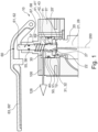
- FIG. 1 A schematic representation of a receiving device 10 for receiving a gas cartridge 20 according to an exemplary embodiment of the present invention is shown.
- the receiving device 10 is part of a carbonation machine 1 or can be connected to a carbonation machine 1.
- a Gas cartridge 20 is received by means of the receiving device 10.
- the gas cartridge 20 is a pressure-stable cartridge, in whose interior 21 a gas 28, in particular CO2 , is enclosed at high pressure.
- the gas cartridge 20 provides the gas 28 for carbonating a liquid 4 arranged in an interior 3 of a bottle 2.
- the receiving device 10 is configured such that the gas cartridge 20 can be attached to the carbonation machine 1 via the receiving device 10.
- the receiving device 10 has a guide element 11 with a recess 11'.
- a pressure transmission means 40 is arranged in the recess 11'. Both the guide element 11 and the pressure transmission means 40 can each be one-piece or multi-piece components.
- the receiving device 10 further comprises a spring device 67, in particular comprising a helical spring 68.
- the spring device 67 is arranged between the pressure transmission means 40 and a horizontal region of the guide element 11.
- the receiving device 10 it is possible for the receiving device 10 to be moved onto the gas cartridge 20 from above.
- a tilting/pivoting movement of the gas cartridge 20 is also conceivable.
- the gas cartridge 20 When the gas cartridge 20 is inserted, the gas cartridge 20 is moved relative to the pressure transmission means 40 and pushes it upwards, so that the spring device 67 is compressed and pretensioned.
- the spring device 67 With the aid of the spring device 67, gas cartridges 20 of different heights can be received by the receiving device 10, and advantageous compensation for the different gas cartridge heights can take place.
- the pressure transmission means 40 comprises a recess 43 arranged centrally in the pressure transmission means 40.
- An opening means 61 which comprises a rod-shaped element 62, extends through the recess 43 of the pressure transmission means 40.
- Different cross-sectional areas for the rod-shaped element 62 and the recess 43 are conceivable, for example, circular cross-sections.
- the opening means 61, in particular the rod-shaped element 62, can be guided through a through-opening of the sealing ring 32. When carbonization is initiated, the rod-shaped element 62 is guided downward parallel to the central axis 200 of the gas cartridge 20, thereby opening the closure means 27 of the gas cartridge 20.
- the receiving device 10 and in particular the opening means 61 are shown in a starting position.
- the starting position relates to a state in which the gas cartridge 20 has already been inserted into the receiving device 10, but no carbonization has yet been carried out (i.e., for example, a state before the start of carbonation).
- the opening means 61 in particular the rod-shaped element 62, is preferably already guided up to a closure means 27 of the gas cartridge 20.
- the position of the opening means 61 in the starting position depends on the height of the gas cartridge 20, wherein the opening means 61 is arranged, for example, such that the opening means 61 rests on the gas cartridge 20 or on the closure means 27 of the gas cartridge 20.
- the opening means 61 is guided in the starting position in the direction of the gas cartridge 20 by the downward force exerted on the pressure transmission means 40 by means of the spring device 67.
- the opening means 61 has a guiding means 69, for example a projection partially or completely encircling the rod-shaped element 62. Due to the spring device 67, the pressure transmission means 40 is already guided in the starting position in the direction of the gas cartridge 20 (i.e. in Figure 1 downwards). In this case, it is possible that the carrying means 69 engages with the pressure transmission means 40, so that the opening means 61 is also pushed in the direction of the gas cartridge 20 and is already positioned close to the gas cartridge 20 in the starting position.
- a further sealing means 50 in particular a further sealing ring 51, is arranged between an inner wall 12 of the guide element 11 and the pressure transmission means 40.
- the inner wall 12 of the guide element 11 is in particular a wall forming the recess 11' of the guide element 11.
- the further sealing means 50 is provided to seal the transition between the inner wall 12 of the guide element 11 and the pressure transmission means 40.
- the further sealing means 50 also seals the pressure chamber 30 (and thus also the gas connection 100 at this point) to the outside.
- a yet further sealing means 55 in particular in the form of a sealing ring 56, is arranged in an upper region of the guide element 11, in particular in a guide channel 57 of the guide element 11, in which the opening means 61 is partially arranged.
- the further sealing means 55 is arranged between the guide element 11 and the opening means 61 and thus seals the transition between the guide element 11 and the opening means 61 to the outside during carbonization.
- the further sealing means 55 during carbonation, the pressure chamber 30 (and thus also the gas connection 100 at this point) also discharges to the outside.
- a gas channel 42 is formed between the rod-shaped element 62 and the sealing ring 32, as well as between the rod-shaped element 62 and the pressure transmission means 40.
- the gas channel 42 connects the interior 21 of the gas cartridge 20 to the pressure chamber 30 of the receiving device 10.
- the pressure chamber 30 is formed partially or completely between the pressure transmission element 40 and the guide element 11.
- the gas channel 42 and the pressure chamber 30 are, in particular, part of a gas connection 100, which is formed during carbonation between the interior 21 of the gas cartridge 20 and the interior 3 of the bottle 2 and via which gas 28 passes from the interior 21 of the gas cartridge 20 into the interior 3 of the bottle 2.
- Gas 28 from the gas cartridge 20 can thus enter the pressure chamber 30 via the gas channel 42, whereby an overpressure can be generated in the pressure chamber 30.
- This overpressure in the pressure chamber 30 pushes the pressure transmission means 40 downward, i.e., toward the gas cartridge 20.
- the pressure transmission means 40 presses the sealing means 31, i.e., in particular, the sealing ring 32, onto the mouth region 20' of the gas cartridge 20.
- the transitions between the gas cartridge 20, the sealing means 31, and the pressure transmission means 40 are sealed to the outside.
- the pressure chamber 30 thus automatically pneumatically seals the gas connection 100, in particular the gas channel 42, to the outside when the gas cartridge 20 is opened during carbonation.
- the overpressure built up in the pressure chamber 30 during carbonation which presses the pressure transmission means 40 towards the gas cartridge 20, advantageously and securely clamps and fastens the gas cartridge 20 in the carbonation machine 1.
- the gas cartridge 20 is clamped or clamped between the pressure transmission means 40 and/or the sealing means 31 on its upper side 22 and a counter element 25, for example a base region 26 of the receiving device 10 or the carbonation machine 1, on its underside 23.
- the pressure chamber 30 particularly advantageously provides both a pneumatic and automatic sealing of the gas connection 100 to the outside and a secure and stable fastening of the gas cartridge 20 in the receiving device 10, particularly during carbonation. Gas cartridges 20 with different dimensions and tolerances can be particularly advantageously fastened using the receiving device 10.
- both gas cartridges 20 with a thread and gas cartridges 20 without a thread can be used, whereby the possibly existing thread of a gas cartridge 20 for fastening and securing the gas cartridge 20 to the receiving device 10 is not must be used.
- the cumbersome screwing in of the gas cartridges 20 for fastening the gas cartridges 20 to a carbonation machine 1 can be particularly advantageously dispensed with.
- the carbonation machine 1 further comprises an actuating device 60.
- the opening means 61 in particular the rod-shaped element 62, can be moved downwards in order to open the closure means 27 of the gas cartridge 20 and start the carbonation process.
- the actuating device 60 comprises a lever device 63.
- the lever device 63 can, for example, be actuated directly by a user or be connected to a button, in particular a push button, wherein, when the button is actuated by the user, the lever device 63 is moved by the movement of the button.
- the arrow marked with the reference numeral 128 indicates the gas flow 128 of the gas 28 from the gas cartridge 20 toward the bottle 2 during carbonation, i.e., when the closure means 27 is open.
- FIG 2 A schematic representation of a carbonation machine 1 according to an exemplary embodiment of the present invention is shown.
- a gas cartridge 2 is arranged in the carbonation machine 1, which provides a gas 28 for carbonating the liquid 4 located in the interior 3 of the bottle 2.
- the gas cartridge 2 is, for example, held in the cylinder by means of a receiving device 10 according to the Figure 1 shown embodiment is attached to the carbonation machine 1.
- the upper area of the receiving device 10 is in the Figure 2 not shown in detail.
- the bottle 2 is attached to the carbonation machine 1 by means of a further receiving device 80. Both the bottle 2 and the gas cartridge 20 are separable from the carbonation machine 1 and, in particular, removable from the carbonation machine 1.
- a gas supply means 81 which forms part of the gas connection 100 between the bottle 2 and the interior 21 of the gas cartridge 20 during carbonation, projects into the interior 3 of the bottle 2.
- the gas 28 can reach the interior of the bottle 2 via the gas supply means 81, so that the liquid 4 can be carbonated. It is conceivable that the carbonation can be started by a user actuating an actuating device 60.
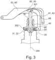
- FIG 3 A schematic representation of a receiving device 10 for receiving a gas cartridge 20 according to an exemplary embodiment of the present invention is shown.
- the receiving device 10 is part of a carbonation machine 1 or can be connected to a carbonation machine 1.
- a gas cartridge 20 is received by means of the receiving device 10.
- the gas cartridge 20 is a pressure-resistant cartridge, in whose interior 21 a gas 28, in particular CO 2 , is enclosed at high pressure.
- the gas cartridge provides the gas 28 for carbonation of a liquid 4 arranged in an interior 3 of a bottle 2.
- a height compensation means 65' for compensating different heights of gas cartridges 20 is shown, wherein the height compensation means 65' comprises a wedge-shaped element 65.
- the area around the pressure chamber 30 of the receiving device 10 is shown in the illustration of Figure 3 not shown in full, but can be used, for example, according to the Figure 1 shown embodiment.
- the wedge-shaped element 65 is arranged between the opening means 61 and the actuating means 60', in particular the lever device 63. With the aid of the wedge-shaped element 65, advantageous height compensation can be achieved in the receiving device 10 and/or actuating device for different gas cartridges 20, in particular with different heights.
- the opening means 61 is connected to a lever system 66 via a connection 66'.
- the lever system 66 is connected to the wedge-shaped element 65 or the wedge-shaped element 65 is formed as a component of the lever system 66.
- the wedge-shaped element 65 is connected to the opening means 61, in particular the rod-shaped element 62, by means of the lever system 66.
- the opening means 61 guides the wedge-shaped element 65 such that the insertion depth of the wedge-shaped element 65 (in a direction perpendicular to the central axis 200 of the gas cartridge 20) between the opening means 61 and the lever device 63 depends on the position of the opening means 61 (parallel to the central axis 200 of the gas cartridge 20) in its initial position.
- the lever system 66 is therefore designed such that an axial movement 302 of the opening means 61 and/or pressure transmission means 40 parallel to the central axis 200 of the gas cartridge 20 is converted into a lateral movement 301 of the wedge-shaped element 65 perpendicular to the central axis 200 of the gas cartridge 20.
- This lateral movement 301 changes the insertion depth of the wedge-shaped element 65 between the opening means 61 and the lever device 63.
- the wedge-shaped element 65 is moved between the opening means 61 and the lever device 63 via the lever system 66, particularly when inserting the gas cartridge 20.
- the wedge-shaped element 65 By means of the wedge-shaped element 65 it can thus be achieved that already in the initial position of the opening means 61 for gas cartridges 20 with different gas cartridge heights a mechanical contact is formed between the opening means 61 and the lever device 63, since the insertion depth of the wedge-shaped element 65 between the Opening means 61 and the lever device 63 depends on the position of the opening means 61 in the starting position.
- the wedge-shaped element 65 is thus adjusted depending on the position of the opening means 61 in the starting position (with the gas cartridge 20 inserted).
- the pressure point or actuation point of the actuation device (for example, a push button or a lever device) is therefore the same or at least very similar for the user for different gas cartridges 20 with different heights.
- a push button or a lever device 63 triggers at the same actuation point for different gas cartridges 20 with different heights, since the wedge-shaped element 65 compensates for the height differences.
- the wedge-shaped element 65 compensates for the height differences.
- FIG 4 is a schematic representation of a part of a receiving device 10 for receiving a gas cartridge 20 according to an exemplary embodiment of the present invention.
- the area around the pressure chamber 30 of the receiving device 10 is shown in the representation of the Figure 4 not shown in full, but can be used, for example, according to the Figure 1 shown embodiment.
- a height compensation means 65' for compensating for different heights of gas cartridges 20 is shown, wherein the height compensation means 65' is in a position that it assumes when a gas cartridge 20 with a comparatively large gas cartridge height is inserted.
- the opening means 61 and the pressure transmission means 40 are positioned relatively high in their initial position, i.e., displaced relatively far upwards along their potential for axial movement 302.
- the lever system 66 Via the lever system 66, the wedge-shaped element 65 is therefore guided comparatively far out of the area between the opening means 61 and the lever device 63 along its lateral movement 301, thus having only a small insertion depth between the opening means 61 and the lever device 63.
- the opening means 61 is positioned comparatively high due to the great height of the gas cartridge 20, a mechanical contact is nevertheless formed between the opening means 61 and the lever device 63 via the wedge-shaped element 65 in the starting position shown.
- the lever device 63 does not have to be moved downwards until it reaches the opening means 61, but rather, there is a well-defined pressure point.
- FIG 5 is a schematic representation of a part of a receiving device 10 for receiving a gas cartridge 20 according to the Figure 4 shown exemplary embodiment of the present invention, wherein the height compensation means 65' is in a position which it assumes when an inserted gas cartridge 20 with a Figure 4
- the area around the pressure chamber 30 of the receiving device 10 is shown in the illustration of the Figure 5 not shown completely.
- the opening means 61 and the pressure transmission means 40 are Figure 4 lower height of the gas cartridge 20 in its initial position positioned slightly lower, i.e. along its axial movement 302 compared to the Figure 4 shifted downward.
- the wedge-shaped element 65 is therefore inserted deeper into the area between the opening means 61 and the lever device 63 along its lateral movement 301, thus having a greater insertion depth between the opening means 61 and the lever device 63. Because the wedge-shaped element 65 is guided in this way via the lever system 66, in the initial position, mechanical contact is also formed between the opening means 61 and the lever device 63 via the wedge-shaped element 65. The pressure point of the actuating device therefore remains the same for the user.
Landscapes
- Chemical & Material Sciences (AREA)
- Chemical Kinetics & Catalysis (AREA)
- Engineering & Computer Science (AREA)
- Mechanical Engineering (AREA)
- General Engineering & Computer Science (AREA)
- Filling Or Discharging Of Gas Storage Vessels (AREA)
- Treatment Of Fiber Materials (AREA)
Claims (15)
- Dispositif de réception (10) destiné à recevoir une cartouche de gaz (20) pour une machine de carbonisation (1),
dans lequel le dispositif de réception (10) comprend une chambre de pression (30), le dispositif de réception (10) étant agencé de telle sorte qu'à l'aide d'une surpression pouvant être générée dans la chambre de pression (30)-- un moyen d'étanchéité (31) peut être pressé sur la cartouche de gaz (20) et/ou-- la cartouche de gaz (20) peut être fixée à la machine de carbonisation (1), caractérisée en ce que-- le dispositif de réception (10) comprend un moyen de transmission de pression (40) et est agencé de telle sorte que le moyen de transmission de pression (40) presse le moyen d'étanchéité (31) sur la cartouche de gaz (20) par la surpression générée dans la chambre de pression (30) - lors de la carbonisation,-- le dispositif de réception (10) comprend un dispositif à ressort (67), une force pouvant être exercée sur le moyen de transmission de pression (40), en particulier à l'aide du dispositif à ressort (67). - Dispositif de réception (10) selon la revendication 1, dans lequel le dispositif de réception (10) est agencé de telle sorte que - lors d'une carbonisation - la chambre de pression (30) est reliée à un espace intérieur (21) de la cartouche de gaz (20) de telle sorte que la surpression est générée dans la chambre de pression (30), en particulier pendant la carbonisation.
- Dispositif de réception (10) selon l'une des revendications précédentes, dans lequel le dispositif de réception (10) est agencé de telle sorte que - en particulier lors de la carbonisation - à l'aide de la surpression générée dans la chambre de pression (30):-- le moyen d'étanchéité (31) est pressé sur la cartouche de gaz (20), en particulier sur une zone d'embouchure (20') de la cartouche de gaz (20), et/ou-- la cartouche de gaz (20) est fixée, en particulier serrée, sur la machine de carbonisation (1).
- Dispositif de réception (10) selon l'une quelconque des revendications précédentes, dans lequel la chambre de pression (30) fait partie d'une connexion de gaz (100) à travers laquelle le gaz (28) peut être transporté de l'espace intérieur (21) de la cartouche de gaz (20) - en particulier lors de la carbonisation - dans une bouteille (2), en particulier dans une bouteille remplie d'un liquide (4).
- Dispositif de réception (10) selon l'une quelconque des revendications précédentes, dans lequel le moyen de transmission de pression (40) est mobile, le moyen de transmission de pression (40) formant une partie d'une limite (41) et/ou d'une paroi (41') de la chambre de pression (30).
- Dispositif de réception (10) selon l'une quelconque des revendications précédentes, dans lequel le moyen d'étanchéité (31) est disposé partiellement ou totalement entre le moyen de transmission de pression (40) et la cartouche de gaz (20), notamment entre le moyen de transmission de pression (40) et une zone d'embouchure (20') de la cartouche de gaz (20).
- Dispositif de réception (10) selon l'une quelconque des revendications précédentes, dans lequel le dispositif de réception (10) est agencé de telle sorte que la cartouche de gaz(20) - en particulier lors de la carbonisation - est serrée à l'aide du moyen de transmission de pression (40) et/ou est fixée dans le dispositif de réception (10) et/ou le dispositif de réception (10) est agencé de telle sorte que la cartouche de gaz (20) - en particulier lors de la carbonisation - est serrée entre le moyen d'étanchéité (31) et/ou le moyen de transmission de pression (40) sur son côté supérieur.(22) et un contre-élément (25), en particulier une zone de fond (26) de la machine de carbonisation (1), est serrée sur sa face inférieure (23).
- Dispositif de réception (10) selon l'une des revendications précédentes, dans lequel le dispositif de réception (10) comprend un élément de guidage (11), le moyen de transmission de pression (40) étant disposé à l'intérieur d'un évidement (11') de l'élément de guidage (11), le moyen de transmission de pression (40) étant de préférence mobile à l'intérieur de l'évidement (11') de l'élément de guidage (11), notamment parallèlement à un axe central (200) de la cartouche de gaz (20) lorsque celle-ci est placée dans le dispositif de réception (10), un autre moyen d'étanchéité (50) étant de préférence disposé entre une paroi intérieure (12) de l'élément de guidage (11) et le moyen de transmission de pression (40).
- Machine de carbonisation (1), comprenant un dispositif de réception (10) pour recevoir une cartouche de gaz (20) selon l'une des revendications précédentes.
- Machine de carbonisation (1) selon la revendication 9, dans laquelle la machine de carbonisation (1) comprend un dispositif d'actionnement (60) pour le démarrage et/ou l'exécution d'une carbonisation, en particulier par un utilisateur.
- Machine de carbonisation (1) selon la revendication 10, dans laquelle le dispositif d'actionnement (60) comporte un moyen d'ouverture (61) pour ouvrir la cartouche de gaz (20), le moyen d'ouverture (61) pouvant notamment être transféré d'une position initiale à une position de carbonisation, le moyen d'ouverture (61) étant disposé dans la position de carbonisation lors de la carbonisation.
- Machine de carbonisation (1) selon la revendication 11, dans laquelle le moyen d'ouverture (61) ouvre, dans la position de carbonisation, un moyen de fermeture (27) de la cartouche de gaz (20), en particulier de telle sorte que du gaz peut s'échapper de l'espace intérieur (21) de la cartouche de gaz (20) et/ou la connexion de gaz (100) est formée entre l'espace intérieur (21) de la cartouche de gaz (20) et la bouteille (2).
- Machine de carbonisation (1) selon l'une des revendications 11 ou 12, dans laquelle le moyen d'ouverture (61) comprend un élément en forme de tige (62) ou est configuré comme un élément en forme de tige (62).
- Machine de carbonisation (1) selon l'une quelconque des revendications 10 à 13, dans laquelle le dispositif d'actionnement (60) comprend un moyen d'actionnement (60'), notamment un dispositif de levier (63) et/ou un bouton-poussoir, le moyen d'ouverture (61) étant apte à passer de sa position initiale à la position de carbonisation, notamment lors d'un actionnement du moyen d'actionnement (60') par un utilisateur.
- Procédé d'utilisation d'une machine de carbonisation (1) selon l'une quelconque des revendications 9 à 14,dans lequel une bouteille (2) remplie d'un liquide est montée sur la machine de carbonisation (1),dans lequel une carbonisation du liquide (2) est effectuée au moyen de la machine de carbonisation,dans lequel - lors de l'exécution de la carbonisation - une surpression est générée dans la chambre de pression (30) du dispositif de réception (10),dans lequel, à l'aide de la surpression générée dans la chambre de pression (30)-- un moyen d'étanchéité (31) est pressé sur la cartouche de gaz (20) et/ou-- la cartouche de gaz (20) est fixée à la machine de carbonisation (10).
Applications Claiming Priority (2)
| Application Number | Priority Date | Filing Date | Title |
|---|---|---|---|
| DE102021207554 | 2021-07-15 | ||
| PCT/EP2022/069785 WO2023285614A1 (fr) | 2021-07-15 | 2022-07-14 | Dispositif de réception pour recevoir une cartouche de gaz pour une machine de carbonatation ; machine de carbonatation ; procédé d'utilisation d'une machine de carbonatation |
Publications (3)
| Publication Number | Publication Date |
|---|---|
| EP4370824A1 EP4370824A1 (fr) | 2024-05-22 |
| EP4370824B1 true EP4370824B1 (fr) | 2025-06-18 |
| EP4370824C0 EP4370824C0 (fr) | 2025-06-18 |
Family
ID=82655311
Family Applications (1)
| Application Number | Title | Priority Date | Filing Date |
|---|---|---|---|
| EP22744464.3A Active EP4370824B1 (fr) | 2021-07-15 | 2022-07-14 | Dispositif de réception pour recevoir une cartouche de gaz pour une machine de carbonatation; machine de carbonatation; procédé d'utilisation d'une machine de carbonatation |
Country Status (9)
| Country | Link |
|---|---|
| US (1) | US20240316509A1 (fr) |
| EP (1) | EP4370824B1 (fr) |
| CN (1) | CN116583692B (fr) |
| AU (1) | AU2022312158B2 (fr) |
| CA (1) | CA3225685A1 (fr) |
| ES (1) | ES3041804T3 (fr) |
| HU (1) | HUE072781T2 (fr) |
| PL (1) | PL4370824T3 (fr) |
| WO (1) | WO2023285614A1 (fr) |
Families Citing this family (1)
| Publication number | Priority date | Publication date | Assignee | Title |
|---|---|---|---|---|
| US12491480B2 (en) * | 2021-10-08 | 2025-12-09 | Coravin, Inc. | Pressurized gas supply and gas cylinder |
Family Cites Families (11)
| Publication number | Priority date | Publication date | Assignee | Title |
|---|---|---|---|---|
| ZA812894B (en) * | 1980-05-13 | 1982-05-26 | Thorn Cascade Co Ltd | Appliance for making an aerated beverage and a cap for a bottle used therein |
| US4960261A (en) * | 1986-03-17 | 1990-10-02 | Isoworth Limited | Gas cylinder connector |
| GB2188115B (en) * | 1986-03-17 | 1990-04-04 | Isoworth Ltd | Carbonation apparatus and gas connector therefor. |
| GB2218767A (en) * | 1988-05-17 | 1989-11-22 | Isoworth Ltd | Gas cylinder connector |
| IL95413A (en) * | 1990-08-17 | 1994-01-25 | Wiseburgh Peter Hulley Peter | Liquid fermentation device |
| EP1331428B1 (fr) * | 2002-01-23 | 2005-09-07 | Kwc Ag | Joint pour un carbonateur |
| JP3093438U (ja) * | 2002-10-16 | 2003-05-09 | 株式会社旭製作所 | ガス圧力調整供給装置 |
| CN103501884A (zh) * | 2012-03-12 | 2014-01-08 | 气泡饮料系统创新中心有限公司 | 具有压力调节配件的汽水机 |
| JP6262997B2 (ja) * | 2013-11-05 | 2018-01-17 | 株式会社リード | 圧縮ガスのレギュレータと該レギュレータを備えた炭酸ミスト美顔器 |
| CN204394246U (zh) * | 2015-01-12 | 2015-06-17 | 宋宁 | 一种分体式饮料机 |
| IL255921A (en) * | 2017-11-26 | 2018-01-31 | Wilder Haim | Adapter for a pressurized gas container |
-
2022
- 2022-07-14 HU HUE22744464A patent/HUE072781T2/hu unknown
- 2022-07-14 WO PCT/EP2022/069785 patent/WO2023285614A1/fr not_active Ceased
- 2022-07-14 US US18/578,055 patent/US20240316509A1/en active Pending
- 2022-07-14 PL PL22744464.3T patent/PL4370824T3/pl unknown
- 2022-07-14 AU AU2022312158A patent/AU2022312158B2/en active Active
- 2022-07-14 CA CA3225685A patent/CA3225685A1/fr active Pending
- 2022-07-14 CN CN202280007326.XA patent/CN116583692B/zh active Active
- 2022-07-14 ES ES22744464T patent/ES3041804T3/es active Active
- 2022-07-14 EP EP22744464.3A patent/EP4370824B1/fr active Active
Also Published As
| Publication number | Publication date |
|---|---|
| WO2023285614A1 (fr) | 2023-01-19 |
| CA3225685A1 (fr) | 2023-01-19 |
| HUE072781T2 (hu) | 2025-12-28 |
| CN116583692A (zh) | 2023-08-11 |
| AU2022312158A1 (en) | 2024-01-25 |
| EP4370824C0 (fr) | 2025-06-18 |
| EP4370824A1 (fr) | 2024-05-22 |
| PL4370824T3 (pl) | 2025-11-03 |
| US20240316509A1 (en) | 2024-09-26 |
| ES3041804T3 (en) | 2025-11-14 |
| CN116583692B (zh) | 2025-01-03 |
| AU2022312158B2 (en) | 2025-12-18 |
Similar Documents
| Publication | Publication Date | Title |
|---|---|---|
| EP1204555B1 (fr) | Dispositif de conservation d'une bouteille pour boissons ouverte | |
| DE2531697A1 (de) | Vorrichtung zum ausschenken von fluessigkeiten | |
| EP2279786A2 (fr) | Dispositif et procédé de traitement gazeux d'un liquide | |
| EP4370824B1 (fr) | Dispositif de réception pour recevoir une cartouche de gaz pour une machine de carbonatation; machine de carbonatation; procédé d'utilisation d'une machine de carbonatation | |
| EP2115344A1 (fr) | Dispositif de raccordement permettant de raccorder un contenant à fluide sous pression à une tubulure de remplissage d'un réservoir gpl | |
| EP1660402A1 (fr) | Dispositif et procede de remplissage a contre-pression | |
| EP1721864B1 (fr) | Fût | |
| EP0867219B1 (fr) | Appareil permettant d'additioner du gaz carbonique à un liquide | |
| EP1879828A1 (fr) | Dispositif pour remplir des recipients | |
| DE4324592C1 (de) | Verfahren und Vorrichtung zum Einfüllen einer Flüssigkeit in Gefäße | |
| EP3141791B1 (fr) | Système de fourniture de gaz | |
| EP3927647B1 (fr) | Dispositif et robinetterie sanitaire pour le remplissage d'un récipient avec liquide carbonaté | |
| EP0054717A1 (fr) | Dispositif pour prise de gaz | |
| WO2023052460A1 (fr) | Dispositif de réception permettant de recevoir une bouteille sur une machine à gazéifier, machine à gazéifier, et procédé d'utilisation d'une machine à gazéifier | |
| DE19850382B4 (de) | Vorrichtung zum Ablaß des in einem Bauteil eines Kraftfahrzeuges enthaltenen Öls | |
| DE19805198A1 (de) | Vorrichtung zum Anreichern von Flüssigkeiten mit Gasen | |
| DE102007030554B4 (de) | Überlaufvorrichtung für einen Flüssigkeitsbehälter | |
| DE10102158A1 (de) | Verfahren und Vorrichtung zum Erzeugen einer mit Gas angereicherten Flüssigkeit, insbesondere eines mit Kohlensäure und Sauerstoff angereicherten Getränks, Behälter und Getränk | |
| AT526082B1 (de) | Schmelzetransportvorrichtung | |
| EP4267288B1 (fr) | Dispositif de réception pour recevoir une bouteille sur une machine à gazéifier, machine à gazéifier et procédé d'utilisation d'une machine à gazéifier | |
| EP0309612A1 (fr) | Dispositif pour vider des bouteilles | |
| DE102010049024B4 (de) | Ventilanordnung für einen Getränkebehälter | |
| DE202024001681U1 (de) | Wassersprudler | |
| EP4399978A1 (fr) | Récipient sous pression pour gaz et boissons avec récipient sous pression | |
| DE4204660C2 (de) | Vorrichtung für die Entnahme von unter dem Druck eines Druckgases stehenden Flüssigkeiten aus einem Behälter |
Legal Events
| Date | Code | Title | Description |
|---|---|---|---|
| STAA | Information on the status of an ep patent application or granted ep patent |
Free format text: STATUS: UNKNOWN |
|
| STAA | Information on the status of an ep patent application or granted ep patent |
Free format text: STATUS: THE INTERNATIONAL PUBLICATION HAS BEEN MADE |
|
| PUAI | Public reference made under article 153(3) epc to a published international application that has entered the european phase |
Free format text: ORIGINAL CODE: 0009012 |
|
| STAA | Information on the status of an ep patent application or granted ep patent |
Free format text: STATUS: REQUEST FOR EXAMINATION WAS MADE |
|
| 17P | Request for examination filed |
Effective date: 20240215 |
|
| AK | Designated contracting states |
Kind code of ref document: A1 Designated state(s): AL AT BE BG CH CY CZ DE DK EE ES FI FR GB GR HR HU IE IS IT LI LT LU LV MC MK MT NL NO PL PT RO RS SE SI SK SM TR |
|
| DAV | Request for validation of the european patent (deleted) | ||
| DAX | Request for extension of the european patent (deleted) | ||
| GRAP | Despatch of communication of intention to grant a patent |
Free format text: ORIGINAL CODE: EPIDOSNIGR1 |
|
| STAA | Information on the status of an ep patent application or granted ep patent |
Free format text: STATUS: GRANT OF PATENT IS INTENDED |
|
| INTG | Intention to grant announced |
Effective date: 20250212 |
|
| GRAS | Grant fee paid |
Free format text: ORIGINAL CODE: EPIDOSNIGR3 |
|
| GRAA | (expected) grant |
Free format text: ORIGINAL CODE: 0009210 |
|
| STAA | Information on the status of an ep patent application or granted ep patent |
Free format text: STATUS: THE PATENT HAS BEEN GRANTED |
|
| AK | Designated contracting states |
Kind code of ref document: B1 Designated state(s): AL AT BE BG CH CY CZ DE DK EE ES FI FR GB GR HR HU IE IS IT LI LT LU LV MC MK MT NL NO PL PT RO RS SE SI SK SM TR |
|
| REG | Reference to a national code |
Ref country code: GB Ref legal event code: FG4D Free format text: NOT ENGLISH |
|
| REG | Reference to a national code |
Ref country code: CH Ref legal event code: EP |
|
| REG | Reference to a national code |
Ref country code: DE Ref legal event code: R096 Ref document number: 502022004347 Country of ref document: DE |
|
| REG | Reference to a national code |
Ref country code: CH Ref legal event code: EP |
|
| REG | Reference to a national code |
Ref country code: IE Ref legal event code: FG4D Free format text: LANGUAGE OF EP DOCUMENT: GERMAN |
|
| U01 | Request for unitary effect filed |
Effective date: 20250717 |
|
| U07 | Unitary effect registered |
Designated state(s): AT BE BG DE DK EE FI FR IT LT LU LV MT NL PT RO SE SI Effective date: 20250723 |
|
| U20 | Renewal fee for the european patent with unitary effect paid |
Year of fee payment: 4 Effective date: 20250902 |
|
| PGFP | Annual fee paid to national office [announced via postgrant information from national office to epo] |
Ref country code: ES Payment date: 20250910 Year of fee payment: 4 |
|
| PG25 | Lapsed in a contracting state [announced via postgrant information from national office to epo] |
Ref country code: GR Free format text: LAPSE BECAUSE OF FAILURE TO SUBMIT A TRANSLATION OF THE DESCRIPTION OR TO PAY THE FEE WITHIN THE PRESCRIBED TIME-LIMIT Effective date: 20250919 Ref country code: NO Free format text: LAPSE BECAUSE OF FAILURE TO SUBMIT A TRANSLATION OF THE DESCRIPTION OR TO PAY THE FEE WITHIN THE PRESCRIBED TIME-LIMIT Effective date: 20250918 |
|
| PGFP | Annual fee paid to national office [announced via postgrant information from national office to epo] |
Ref country code: HU Payment date: 20250911 Year of fee payment: 4 |
|
| PG25 | Lapsed in a contracting state [announced via postgrant information from national office to epo] |
Ref country code: HR Free format text: LAPSE BECAUSE OF FAILURE TO SUBMIT A TRANSLATION OF THE DESCRIPTION OR TO PAY THE FEE WITHIN THE PRESCRIBED TIME-LIMIT Effective date: 20250618 |
|
| PGFP | Annual fee paid to national office [announced via postgrant information from national office to epo] |
Ref country code: CH Payment date: 20250903 Year of fee payment: 4 |
|
| PG25 | Lapsed in a contracting state [announced via postgrant information from national office to epo] |
Ref country code: RS Free format text: LAPSE BECAUSE OF FAILURE TO SUBMIT A TRANSLATION OF THE DESCRIPTION OR TO PAY THE FEE WITHIN THE PRESCRIBED TIME-LIMIT Effective date: 20250918 |
|
| PGFP | Annual fee paid to national office [announced via postgrant information from national office to epo] |
Ref country code: IE Payment date: 20250807 Year of fee payment: 4 |
|
| REG | Reference to a national code |
Ref country code: SK Ref legal event code: T3 Ref document number: E 47069 Country of ref document: SK |
|
| REG | Reference to a national code |
Ref country code: ES Ref legal event code: FG2A Ref document number: 3041804 Country of ref document: ES Kind code of ref document: T3 Effective date: 20251114 |
|
| REG | Reference to a national code |
Ref country code: HU Ref legal event code: AG4A Ref document number: E072781 Country of ref document: HU |
|
| PG25 | Lapsed in a contracting state [announced via postgrant information from national office to epo] |
Ref country code: IS Free format text: LAPSE BECAUSE OF FAILURE TO SUBMIT A TRANSLATION OF THE DESCRIPTION OR TO PAY THE FEE WITHIN THE PRESCRIBED TIME-LIMIT Effective date: 20251018 |
|
| PG25 | Lapsed in a contracting state [announced via postgrant information from national office to epo] |
Ref country code: SM Free format text: LAPSE BECAUSE OF FAILURE TO SUBMIT A TRANSLATION OF THE DESCRIPTION OR TO PAY THE FEE WITHIN THE PRESCRIBED TIME-LIMIT Effective date: 20250618 |
|
| PG25 | Lapsed in a contracting state [announced via postgrant information from national office to epo] |
Ref country code: CZ Free format text: LAPSE BECAUSE OF FAILURE TO SUBMIT A TRANSLATION OF THE DESCRIPTION OR TO PAY THE FEE WITHIN THE PRESCRIBED TIME-LIMIT Effective date: 20250618 |
|
| PGFP | Annual fee paid to national office [announced via postgrant information from national office to epo] |
Ref country code: PL Payment date: 20250813 Year of fee payment: 4 |
|
| PGFP | Annual fee paid to national office [announced via postgrant information from national office to epo] |
Ref country code: SK Payment date: 20250808 Year of fee payment: 4 |
|
| PG25 | Lapsed in a contracting state [announced via postgrant information from national office to epo] |
Ref country code: MC Free format text: LAPSE BECAUSE OF FAILURE TO SUBMIT A TRANSLATION OF THE DESCRIPTION OR TO PAY THE FEE WITHIN THE PRESCRIBED TIME-LIMIT Effective date: 20250618 |
|
| PLBE | No opposition filed within time limit |
Free format text: ORIGINAL CODE: 0009261 |
|
| STAA | Information on the status of an ep patent application or granted ep patent |
Free format text: STATUS: NO OPPOSITION FILED WITHIN TIME LIMIT |
|
| REG | Reference to a national code |
Ref country code: CH Ref legal event code: L10 Free format text: ST27 STATUS EVENT CODE: U-0-0-L10-L00 (AS PROVIDED BY THE NATIONAL OFFICE) Effective date: 20260430 |