EP4371642A2 - Dispositif amélioré pour collecter des matières particulaires - Google Patents
Dispositif amélioré pour collecter des matières particulaires Download PDFInfo
- Publication number
- EP4371642A2 EP4371642A2 EP24154176.2A EP24154176A EP4371642A2 EP 4371642 A2 EP4371642 A2 EP 4371642A2 EP 24154176 A EP24154176 A EP 24154176A EP 4371642 A2 EP4371642 A2 EP 4371642A2
- Authority
- EP
- European Patent Office
- Prior art keywords
- filter
- particulate matter
- container
- collection
- retainer
- Prior art date
- Legal status (The legal status is an assumption and is not a legal conclusion. Google has not performed a legal analysis and makes no representation as to the accuracy of the status listed.)
- Granted
Links
Images


Classifications
-
- G—PHYSICS
- G01—MEASURING; TESTING
- G01N—INVESTIGATING OR ANALYSING MATERIALS BY DETERMINING THEIR CHEMICAL OR PHYSICAL PROPERTIES
- G01N1/00—Sampling; Preparing specimens for investigation
- G01N1/02—Devices for withdrawing samples
- G01N1/22—Devices for withdrawing samples in the gaseous state
- G01N1/2202—Devices for withdrawing samples in the gaseous state involving separation of sample components during sampling
- G01N1/2205—Devices for withdrawing samples in the gaseous state involving separation of sample components during sampling with filters
-
- B—PERFORMING OPERATIONS; TRANSPORTING
- B01—PHYSICAL OR CHEMICAL PROCESSES OR APPARATUS IN GENERAL
- B01D—SEPARATION
- B01D46/00—Filters or filtering processes specially modified for separating dispersed particles from gases or vapours
- B01D46/0002—Casings; Housings; Frame constructions
- B01D46/0005—Mounting of filtering elements within casings, housings or frames
-
- B—PERFORMING OPERATIONS; TRANSPORTING
- B01—PHYSICAL OR CHEMICAL PROCESSES OR APPARATUS IN GENERAL
- B01D—SEPARATION
- B01D39/00—Filtering material for liquid or gaseous fluids
- B01D39/14—Other self-supporting filtering material ; Other filtering material
- B01D39/16—Other self-supporting filtering material ; Other filtering material of organic material, e.g. synthetic fibres
- B01D39/1669—Cellular material
- B01D39/1676—Cellular material of synthetic origin
-
- B—PERFORMING OPERATIONS; TRANSPORTING
- B01—PHYSICAL OR CHEMICAL PROCESSES OR APPARATUS IN GENERAL
- B01D—SEPARATION
- B01D46/00—Filters or filtering processes specially modified for separating dispersed particles from gases or vapours
- B01D46/0002—Casings; Housings; Frame constructions
- B01D46/0004—Details of removable closures, lids, caps or filter heads
-
- B—PERFORMING OPERATIONS; TRANSPORTING
- B01—PHYSICAL OR CHEMICAL PROCESSES OR APPARATUS IN GENERAL
- B01D—SEPARATION
- B01D46/00—Filters or filtering processes specially modified for separating dispersed particles from gases or vapours
- B01D46/0002—Casings; Housings; Frame constructions
- B01D46/0015—Throw-away type filters
-
- B—PERFORMING OPERATIONS; TRANSPORTING
- B01—PHYSICAL OR CHEMICAL PROCESSES OR APPARATUS IN GENERAL
- B01D—SEPARATION
- B01D46/00—Filters or filtering processes specially modified for separating dispersed particles from gases or vapours
- B01D46/24—Particle separators, e.g. dust precipitators, using rigid hollow filter bodies
- B01D46/2403—Particle separators, e.g. dust precipitators, using rigid hollow filter bodies characterised by the physical shape or structure of the filtering element
-
- G—PHYSICS
- G01—MEASURING; TESTING
- G01N—INVESTIGATING OR ANALYSING MATERIALS BY DETERMINING THEIR CHEMICAL OR PHYSICAL PROPERTIES
- G01N1/00—Sampling; Preparing specimens for investigation
- G01N1/02—Devices for withdrawing samples
- G01N1/22—Devices for withdrawing samples in the gaseous state
- G01N1/2273—Atmospheric sampling
-
- G—PHYSICS
- G01—MEASURING; TESTING
- G01N—INVESTIGATING OR ANALYSING MATERIALS BY DETERMINING THEIR CHEMICAL OR PHYSICAL PROPERTIES
- G01N1/00—Sampling; Preparing specimens for investigation
- G01N1/28—Preparing specimens for investigation including physical details of (bio-)chemical methods covered elsewhere, e.g. G01N33/50, C12Q
- G01N1/40—Concentrating samples
- G01N1/4055—Concentrating samples by solubility techniques
-
- B—PERFORMING OPERATIONS; TRANSPORTING
- B01—PHYSICAL OR CHEMICAL PROCESSES OR APPARATUS IN GENERAL
- B01D—SEPARATION
- B01D2265/00—Casings, housings or mounting for filters specially adapted for separating dispersed particles from gases or vapours
- B01D2265/02—Non-permanent measures for connecting different parts of the filter
-
- B—PERFORMING OPERATIONS; TRANSPORTING
- B01—PHYSICAL OR CHEMICAL PROCESSES OR APPARATUS IN GENERAL
- B01D—SEPARATION
- B01D2265/00—Casings, housings or mounting for filters specially adapted for separating dispersed particles from gases or vapours
- B01D2265/04—Permanent measures for connecting different parts of the filter, e.g. welding, glueing or moulding
-
- B—PERFORMING OPERATIONS; TRANSPORTING
- B01—PHYSICAL OR CHEMICAL PROCESSES OR APPARATUS IN GENERAL
- B01D—SEPARATION
- B01D2265/00—Casings, housings or mounting for filters specially adapted for separating dispersed particles from gases or vapours
- B01D2265/06—Details of supporting structures for filtering material, e.g. cores
-
- G—PHYSICS
- G01—MEASURING; TESTING
- G01N—INVESTIGATING OR ANALYSING MATERIALS BY DETERMINING THEIR CHEMICAL OR PHYSICAL PROPERTIES
- G01N1/00—Sampling; Preparing specimens for investigation
- G01N1/02—Devices for withdrawing samples
- G01N1/22—Devices for withdrawing samples in the gaseous state
- G01N1/2202—Devices for withdrawing samples in the gaseous state involving separation of sample components during sampling
- G01N2001/222—Other features
- G01N2001/2223—Other features aerosol sampling devices
-
- G—PHYSICS
- G01—MEASURING; TESTING
- G01N—INVESTIGATING OR ANALYSING MATERIALS BY DETERMINING THEIR CHEMICAL OR PHYSICAL PROPERTIES
- G01N1/00—Sampling; Preparing specimens for investigation
- G01N1/02—Devices for withdrawing samples
- G01N1/22—Devices for withdrawing samples in the gaseous state
- G01N1/2273—Atmospheric sampling
- G01N2001/2276—Personal monitors
-
- G—PHYSICS
- G01—MEASURING; TESTING
- G01N—INVESTIGATING OR ANALYSING MATERIALS BY DETERMINING THEIR CHEMICAL OR PHYSICAL PROPERTIES
- G01N1/00—Sampling; Preparing specimens for investigation
- G01N1/02—Devices for withdrawing samples
- G01N1/22—Devices for withdrawing samples in the gaseous state
- G01N2001/2285—Details of probe structures
- G01N2001/2288—Filter arrangements
-
- G—PHYSICS
- G01—MEASURING; TESTING
- G01N—INVESTIGATING OR ANALYSING MATERIALS BY DETERMINING THEIR CHEMICAL OR PHYSICAL PROPERTIES
- G01N5/00—Analysing materials by weighing, e.g. weighing small particles separated from a gas or liquid
- G01N5/02—Analysing materials by weighing, e.g. weighing small particles separated from a gas or liquid by absorbing or adsorbing components of a material and determining change of weight of the adsorbent, e.g. determining moisture content
Definitions
- This invention relates to air quality, and more particularly to a device for collecting and measuring particulate matter suspended in the ambient air.
- United States Patent number 4,675,034 provides a personal air sampler which is carried by an individual to collect dust to which these individuals are exposed during normal activity.
- the personal air sampler has a removable filter unit having a collection filter to collect a dust sample representative of the total inspirable dust inhaled by the individual.
- the removable filter unit is removed and the collection filter is analyzed accordingly.
- a new collection filter is installed in the filter unit for subsequent use.
- Another object of the present invention is to provide an improved device for collecting particulate matter suspended in the ambient air having a disposable filter cassette.
- Another object of the present invention is to provide an improved device for collecting particulate matter suspended in the ambient air having a two stage filter cassette.
- Another object of the present invention is to provide an improved device for collecting particulate matter suspended in the ambient air having a solvent soluble filter cassette for extracting any collected particulate material from the filter.
- Another object of the present invention is to provide an improved device for collecting particulate matter suspended in the ambient air having a reduced internal volume for enabling local analysis of the collected particulate matter.
- the invention relates to an improved device for collecting particulate matter suspended in the ambient air through the use of a low pressure air source.
- the improved device comprises a container extending between an open first end and a closed second end defining a container interior.
- a container output communicates with the container interior located proximate the closed second end of the container.
- a filter cassette comprising a collection filter is permanently affixed to a filter holder.
- a retainer having a retainer input is secured removably to the open first end of the container for retaining the filter cassette between the retainer input and the container output.
- An output connector connects the container output to the low pressure source for drawing ambient air into the retainer input for enabling the collection filter to collect particulate matter suspended in the ambient air entering the retainer input.
- the filter holder and the filter are disposable.
- the filter is permanently affixed to the filter holder such a fusing methodology or the like.
- the filter holder and the filter are formed of a polymeric material that are soluble in a solvent for extracting any collected particulate material from the filter.
- the cassette includes a foam filter located upstream from the filter for collecting large particulate matter suspended in the ambient air.
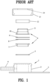
- FIG. 1 is an exploded view of a personal air sampler of the prior art as shown in US Patent US 4,675,034 .
- the personal air sampler has a body 1 of a part-threaded cylinder 2 mounted on a base plate 3.
- a gas exit pipe 4 connects with the inside of the cylinder.
- a synthetic rubber O-seal 5 sits on a shoulder in the top of the cylinder and sealably engages with the bottom shoulder of a filter cassette, 6.
- the cassette 6 comprises an annular bottom part 7 communicating with the inside of cylinder 2.
- the cassette 6 includes a filter paper disc 8, preferably on a fine metal grid support (not shown) with a fine PTFE washer 9 and a cassette top 10.
- the cassette top has an upper cylindrical portion 11 which acts as the lipped entry to the filter cassette.
- a PTFE cylinder 12 sits upon the lower shoulder of the cassette top and transfers pressure from a threaded cap 13 which engages the thread on the cylinder 2.
- the cap has a central aperture 14. As cap 13 is screwed down onto the body of the sampler the cassette top is pressed into sealing engagement with the PFTE washer 9 and the cassette bottom part 7 is pressed into sealing engagement with the O-seal 5 and the body of the sampler.
- a filter cassette is pre-weighed under standard conditions, and, if necessary, stored in a sealed and numbered tin or the like.
- a sampler is assembled and fitted onto the lapel of a user, so that the lipped entry faces outwards, and a standard personal sampler pump (not shown) is attached to gas exit pipe 4.
- a standard personal sampler pump (not shown) is attached to gas exit pipe 4.
- the sampler may be disassembled, and the cassette reweighed.
- all the dust collected within the filter cassette is to be considered as total inspirable dust and therefore is included in the total weight of dust. If desired, the dust deposited on the internal walls may be recovered by washing or brushing out and subjected to more detailed study.
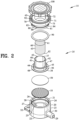
- FIGS. 2-10 are various views of an improved device 15 for collecting particulate matter 16 suspended in the ambient air 18 as shown in FIG. 11 through the use of a low pressure air source 19.
- the device 15 comprises a container 20 extending between an open first end 21 and a closed second end 22.
- the container 20 defines a cylindrical outer diameter 23 and a cylindrical inner diameter 24 defining a container interior 25.
- An annular recess 26 is defined in the cylindrical inner diameter 24 in proximity to the open first end 21 of the container 20.
- a container interior ring 27 extends inwardly from the cylindrical inner diameter 24 in proximity to the closed second end 22 of the container 20.
- the container interior ring 27 defines an interior ring cylindrical diameter 28.
- a container output 29 extends through the container interior ring 27 and communicates with the container interior 25.
- An output connector 30 extends from the cylindrical outer diameter 23 of the container 20 for connecting the container output 29 to the low pressure source 19 illustrated in FIG. 11 .
- a loop 32 extends from the cylindrical outer diameter 23 of the container 20 for affixing the device 15 to an individual (not shown). It should be understood that the device 15 may be affixed to an individual (not shown) by various means and various orientations. AS best shown in FIG. 4 , an operational closure groove 34 is defined into the second end 22 of the container 20.
- a filter cassette 35 comprising a filter holder 40 with a collection filter 50 permanently affixed to the filter holder 40.
- a filter support 55 is positioned under the collection filter 50 for preventing distortion of the collection filter 50 during operation of the device 15.
- An optional foam filter 60 is retained within the filter holder 40 upstream from the collection filter 50.
- a retainer 65 comprises a first ring 70 and a second ring 80.
- the first ring defines a first ring outer cylindrical diameter 71 and a first ring inner cylindrical diameter 72.
- the first ring inner cylindrical diameter 72 defines a retainer input aperture 75.
- the second ring 80 defines a second ring outer diameter 81 and the second ring inner diameter 82.
- an outer shoulder 84 is defined between the first ring outer cylindrical diameter 71 and the second ring outer cylindrical diameter 81.
- An inner shoulder 86 is defined between the first ring inner cylindrical diameter 72 and the second ring inner cylindrical diameter 82.
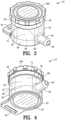
- An annular projection 88 extends outwardly from the second ring outer cylindrical diameter 81.
- the annular projection 88 is configured for engagement with the annular recess 26 of the container 20 for removably securing the retainer 65 to the container 20. It should be appreciated by those skilled in the art that the engagement between the annular projection 88 and the annular recess 26 may take various forms such as frictional engagements, threaded engagements, resilient engagements and the like.
- a seal 90 is disposed between the second ring 80 of the retainer 65 and the flange 48 of the filter cassette 35.
- the seal 90 cooperates with the container interior ring 27 to seal the flange 48 of the filter cassette 35 to both the container 20 and the retainer 35.
- a closure groove 92 is defined in an end of the first ring 70 of the retainer 65.
- a closure 100 includes a closure protrusion 102 configured to engage with the closure groove 93 for removably securing the closure 100 to the retainer 65.
- closure protrusion 102 and the closure groove 93 may take various forms such as frictional engagements, threaded engagements, resilient engagements and the like.
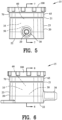
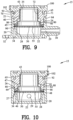
- FIGS. 7 and 8 illustrate the device 15 in an assembled condition suitable for storage and shipping.
- the filter support 55 is positioned on the container interior ring 27 of the container 20.
- the filter holder 40 with the permanently affixed collection filter 50 is positioned on the filter support 55.
- an optional ledge 49 extends inwardly from the shoulder 47 for providing a stop for the optional foam filter 60.
- the optional ledge 49 insures a consistent spacing between the optional foam filter 60 and the collection filter 50.
- the second ring 80 of the retainer 65 is inserted into the container interior 25 of the container 20.
- the annular projection 88 of the retainer 65 engages with the annular recess 26 of the container 20 for removably securing the retainer 65 to the container 20.
- the annular projection 88 of the retainer 65 and annual recess 26 of the container 24 are dimensionally located to squeeze the seal 90 to prevent ambient air 18 from flowing around the flange 48.
- the closure 100 is removably secured to the retainer 65 through the engagement of the closure protrusions 102 with the closure groove 92.
- An output cap show in FIG. 24 , covers the output connector 34 to inhibit entry of contaminants therethrough.
- FIGS. 9 and 10 illustrate the device 15 in an assembled condition suitable for storage and shipping.
- the filter support 55 is positioned on the container interior ring 27 of the container 20.
- the filter holder 40 with the permanently affixed collection filter 50 is positioned on the filter support 55.
- the filter cassette 35 lacks the optional ledge 49 and the optional foam filter 60.
- the second ring 80 of the retainer 65 is inserted into the container interior 25 of the container 20 as set forth with reference to FIGS 7 and 8 .
- FIG. 11 illustrates the device 15 in an assembled condition suitable for operation of the present invention.
- the closure 100 has been removed from the first ring 70 of the retainer 65 and has been affixed to the second end 22 of the container 30.
- the closure protrusion 102 of the closure 100 engages with the operational closure grooves 34 to removably secure the closure 100 to the container 20.
- the engagement between the closure protrusion 102 and operational closure grooves 34 may take various forms such as frictional engagements, threaded engagements, resilient engagements and the like.
- the output connector 30 is connected to the low pressure air source 19 as indicated by the arrow extending from the output connector 30.
- the closure 100 has been removed from the retainer 65 permitting ambient air to be drawn into the first ring inner diameter 72 by the low pressure air source 19.
- the ambient air first encounters the foam filter 60 to collect large particulate matter 16 present in the ambient air 18. Thereafter, the ambient air passes through the collector filter 50 whereat smaller particulate matter is captured by the collection filter 50.
- the low pressure air source 19 is removed from the output connector 30 and the closure 100 is affixed to the retainer 65.
- the device 15 is transported to an appropriate location for an analysis of the particulate matter captured by the filter cassette 35.
- the closure 100 and the retainer 65 are removed from the container 20.
- the filter cassette 35 is removed for analysis by several means.
- filter cassette 35 may be analyzed by the difference in weight of the filter cassette 35 before collection of the particulate matter 16 and after collection of the particulate matter 16.
- the filter cassette 35 has a distinct advantage over the prior art by being low in weight.
- the filter cassette 35 has the advantage of the fused collection filter 50 and eliminates the use of a mechanical connection of a collection filter found in the prior art.
- the filter cassette 35 is disposable.
- the filter cassette 35 presents a new opportunity for analyzing the particulate matter 16 by chemical means.
- the filter cassette 35 including the collection filter 50 and the foam filter 60 are formed from a soluble polymeric material. After the filter cassette 35 including the collection filter 50 and the foam filter 60 are dissolved by a solvent, the remaining precipitate may be quantitatively and/or quantitatively chemically analyzed.
- FIGS. 12-19 illustrate the filter cassette 35 in greater detail.
- the filter cassette 35 extends between a first cassette end 37 and a second cassette and 38.
- the filter cassette 35 includes the filter holder 40 having a first cylindrical portion 41 and a second cylindrical portion 44.
- the first cylindrical portion 41 defines an outer diameter 42 and an inner diameter 43.
- the second cylindrical portion 44 defines an outer diameter 45 and an inner diameter 46.
- a shoulder 47 is located between the first cylindrical portion 41 and the second cylindrical portion 44.
- a flange 48 is affixed to the second cylindrical portion 44 in proximity to the second cassette end 38.
- the flange 48 may be extended to form the optional ledge 49.
- the filter holder 40 including the first cylindrical portion 41 and the second cylindrical portion 44, the flange 48 and the optional ledge 49 are formed as a one piece unit from a polymeric material.
- Polymeric materials suitable for forming the filter holder 40 include polyvinyl chloride (PVC), cellulose or the like.
- the collection filter 50 comprises a sheet filter paper having the proper porosity for collecting minute particulate matter 15 from the ambient air 16.
- the collection filter 50 is permanently affixed to the flange 48 by means such as fusion or any suitable and appropriate means.
- the filter 50 is separate and distinct from the filter holder 40.
- the filter 50 is held in place between the filter holder 40 and the container 20 by a compression engagement
- a separate and distinct filter 50 may be employed when (1) the filter 50 cannot be secured to the filter holder 40 or (2) a special filter material or a special filter coating is required in the filter 50.
- the filter 50 is made of a material that cannot be readily secured to the filter holder 40.
- Some examples are filters made of PTFE, glass fiber, nylon or material that require an undesirable adhesive.
- filters may users desire to utilize specialized filter material and/or filter coating that are not suitable for being secured to the filter holder 40.
- the filter holder 40 is formed from a material having limited moisture absorbing properties.
- the limited moisture absorbing properties of the filter holder 40 provides a stable weight to yield good reproducibility in weight measurements.
- the desired combined weight of the filter holder 40 and the filer 50 is below 600 milligrams.
- the filter holder 40 and the filter 50 are made of the same or similar material to be dissolved by a solvent after the filter 50 collects the particulate matter 16.
- the particulate matter 16 is held in suspension by the solvent
- the filter holder 40 and the filter 50 are made of the same or similar material to impervious to a solvent after the filter 50 collects the particulate matter 16.
- the particulate matter 16 is dissolved from the filter 50 by the solvent. Thereafter, the type and quantity of the particulate matter 16 can be analyzed.
- the filter support 55 is formed from a gas porous material for allowing airflow therethrough for facilitating the collection of the particulate matter 16 by the filter 50.
- a material such as porous polyethylene is useful in such an application. In other instances, it is desirable to select a material for the filter support 55 that is porous for gas but inhibits the passing of a liquid therethrough under ambient gas pressure.
- the foam filter 60 extends from a first foam end 61 to a second form and 62.
- the foam filter 60 defines and outer diameter 63.
- the outer diameter 63 of the foam filter 60 is configured to resiliently engage the inner diameter 43 of the first cylindrical portion 41 of the filter holder 40.
- the foam filter 60 is desirable in collecting larger particulate matter 16, the use of the foam filter 60 may be considered optional in the practice of the present invention.
- the present invention improves upon the personal air sampler set forth in United States Patent number 4,675,034 and provides a device having an improved design and improved filter cassette.
- the improved device has a disposable filter cassette and is capable of having a two stage filter cassette.
- the device may be formed from a solvent soluble filter cassette for extracting any collected particulate material from the filter.
- FIGS. 20-22 illustrating the personal air sampler 15 of the present invention incorporating a volume reducing plug 110. Similar reference characters in FIGS. 20-25 refer to similar parts shown in FIGS. 2-19 .
- the volume reducing plug 110 comprises a top surface 111 and a bottom surface 112 interconnected by a cylindrical sidewall 113.
- An orienting groove 115 is defined in the cylindrical sidewall 113 for orienting the volume reducing plug 110 within the container interior 25 of the container 20.
- the volume reducing plug 110 may be solid or may be fabricated or molded to reduce the volume of the container interior 25 of the container 20.
- a tunnel 120 is defined with the volume reducing plug 110 for communicating the container interior 25 of the container 20 and the container output 29.
- the tunnel 120 comprises an axial tunnel 121 coupled to a radial tunnel 122.
- the interior ring cylindrical diameter 28 includes an orienting rib 36.
- the orienting rib 36 engages with the orienting groove 115 of the volume reducing plug 110 for aligning the radial tunnel 122 with the container output 29.
- FIG. 23 illustrates the collection of particulate matter during the operation of the personal air sampler 15.
- the output connector 30 is connected to the low pressure air source 19 as indicated by the arrow extending from the output connector 30.
- the low pressure air source 19 of the container output 29 is communicated by the tunnel 120 to the container interior 25 of the container 20.
- the ambient air 18 is drawn into the first ring inner diameter 72 by the low pressure air source 19 with particulate material 16 suspended within the ambient air 18 being collected by the collection filter 50.
- FIG. 24 illustrates the initial steps of analyzing the collected particulate material 16.
- An output cap 95 is installed on the output connector 30.
- the output cap 95 comprises a handle 96 and a stopper 98 for providing a fluid tight seal for the output 29.
- a liquid 125 is introduced through the first ring inner diameter 72 to pass through the collection filter 50 and fill the tunnel 120.
- the liquid 125 by be selected to either (1) dissolve the particulate material 16 collected by the collection filter 50 or (2) physically wash or remove the particulate material 16 from the collection filter 50.
- FIG. 25 illustrates the removal of the introduced liquid 125 along with particulate matter 16 captured by the collection filter 50 for local analysis.
- the incorporation of the volume reducing plug 110 substantially reduces the amount of the liquid 125 required for removing the particulate material 16 from the collection filter 50.
- the reduction in the liquid 125 results in a more accurate analysis of the particulate material 16.
- the use of the volume reducing plug 110 permits the immediate analysis of the particulate material 16 at the site of the collection.
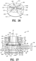
- FIGS. 26 and 27 illustrate a variation of the volume reducing plug 110A shown in FIGS. 20-25 . Similar reference characters in FIGS. 26 and 27 refer to similar parts shown in FIGS. 20-25 .
- the volume reducing plug 110A includes a plurality of radial indentations 130 defines within the top surface 111 of the volume reducing plug 110A.
- Each of the plurality of radial indentations 130 communicates with the tunnel 120. More specifically, the interior end of each of the radial indentations 130 intersects with the axial tunnel 121 to communicate with the radial tunnel 122.
- the plurality of radial indentations 130 provides an enhanced and balanced airflow through the filter 50 and the support 55.
- the particulate matter 16 trapped by the filter 50 is more evenly distributed about the filter 50 by virtue of the inclusion of the plurality of radial indentations 130.
Landscapes
- Chemical & Material Sciences (AREA)
- Life Sciences & Earth Sciences (AREA)
- Health & Medical Sciences (AREA)
- Physics & Mathematics (AREA)
- Chemical Kinetics & Catalysis (AREA)
- Pathology (AREA)
- Analytical Chemistry (AREA)
- Biochemistry (AREA)
- General Health & Medical Sciences (AREA)
- General Physics & Mathematics (AREA)
- Immunology (AREA)
- Molecular Biology (AREA)
- Biomedical Technology (AREA)
- Engineering & Computer Science (AREA)
- Geometry (AREA)
- Sampling And Sample Adjustment (AREA)
Applications Claiming Priority (3)
| Application Number | Priority Date | Filing Date | Title |
|---|---|---|---|
| US201862710399P | 2018-02-16 | 2018-02-16 | |
| EP19754929.8A EP3752019B1 (fr) | 2018-02-16 | 2019-02-14 | Dispositif amélioré de collecte d'une matière particulaire |
| PCT/US2019/018015 WO2019161058A1 (fr) | 2018-02-16 | 2019-02-14 | Dispositif amélioré de collecte d'une matière particulaire |
Related Parent Applications (3)
| Application Number | Title | Priority Date | Filing Date |
|---|---|---|---|
| PCT/US2019/018015 Previously-Filed-Application WO2019161058A1 (fr) | 2018-02-16 | 2019-02-14 | Dispositif amélioré de collecte d'une matière particulaire |
| EP19754929.8A Division EP3752019B1 (fr) | 2018-02-16 | 2019-02-14 | Dispositif amélioré de collecte d'une matière particulaire |
| EP19754929.8A Division-Into EP3752019B1 (fr) | 2018-02-16 | 2019-02-14 | Dispositif amélioré de collecte d'une matière particulaire |
Publications (3)
| Publication Number | Publication Date |
|---|---|
| EP4371642A2 true EP4371642A2 (fr) | 2024-05-22 |
| EP4371642A3 EP4371642A3 (fr) | 2024-08-28 |
| EP4371642B1 EP4371642B1 (fr) | 2025-12-10 |
Family
ID=67616560
Family Applications (2)
| Application Number | Title | Priority Date | Filing Date |
|---|---|---|---|
| EP19754929.8A Active EP3752019B1 (fr) | 2018-02-16 | 2019-02-14 | Dispositif amélioré de collecte d'une matière particulaire |
| EP24154176.2A Active EP4371642B1 (fr) | 2018-02-16 | 2019-02-14 | Dispositif amélioré pour collecter des matières particulaires |
Family Applications Before (1)
| Application Number | Title | Priority Date | Filing Date |
|---|---|---|---|
| EP19754929.8A Active EP3752019B1 (fr) | 2018-02-16 | 2019-02-14 | Dispositif amélioré de collecte d'une matière particulaire |
Country Status (3)
| Country | Link |
|---|---|
| US (2) | US11426689B2 (fr) |
| EP (2) | EP3752019B1 (fr) |
| WO (1) | WO2019161058A1 (fr) |
Families Citing this family (10)
| Publication number | Priority date | Publication date | Assignee | Title |
|---|---|---|---|---|
| USD916248S1 (en) * | 2018-02-16 | 2021-04-13 | Zefon International, Inc. | Filter cassette |
| EP3534138B1 (fr) * | 2018-03-01 | 2024-12-25 | CleanControlling GmbH | Dispositif de collecte de particules transportable |
| US11402304B2 (en) * | 2019-07-03 | 2022-08-02 | Raytheon Technologies Corporation | Environmental sampling system and method |
| US12553885B2 (en) | 2020-05-07 | 2026-02-17 | Hand Held Products, Inc. | Apparatuses, systems, and methods for sample testing |
| US12498328B2 (en) | 2020-05-07 | 2025-12-16 | Hand Held Products, Inc. | Apparatuses, systems, and methods for sample testing |
| US12196672B2 (en) | 2020-05-07 | 2025-01-14 | Hand Held Products, Inc. | Apparatuses, systems, and methods for sample testing |
| US11846574B2 (en) | 2020-10-29 | 2023-12-19 | Hand Held Products, Inc. | Apparatuses, systems, and methods for sample capture and extraction |
| JP2023169740A (ja) * | 2022-05-17 | 2023-11-30 | 学校法人関西文理総合学園 | 粒子状物質の捕集装置及び捕集方法 |
| USD1037407S1 (en) * | 2022-11-18 | 2024-07-30 | 3M Innovative Properties Company | Toilet cleaning cup refill |
| CN118670812B (zh) * | 2024-08-15 | 2024-11-05 | 丹东瑞特科技有限公司 | 一种多膜环境空气颗粒物采样器 |
Family Cites Families (25)
| Publication number | Priority date | Publication date | Assignee | Title |
|---|---|---|---|---|
| US3966439A (en) | 1974-11-11 | 1976-06-29 | Vennos Spyros Lysander N | Fluid sampling device |
| DE3107758A1 (de) * | 1980-03-04 | 1982-01-28 | National Research Development Corp., London | Auswaschvorrichtung |
| FR2531534A1 (fr) | 1982-08-03 | 1984-02-10 | Charbonnages De France | Capteur individuel portatif de poussieres |
| GB2158233B (en) | 1984-05-03 | 1987-10-14 | Coal Ind | Improvements in dust collection |
| US5012681A (en) * | 1987-08-05 | 1991-05-07 | Lentzen Donald E | Sampling procedures and protective layers for the preservation of particulates obtained by filter collection and impingement operations |
| JPH0534736Y2 (fr) * | 1989-07-11 | 1993-09-02 | ||
| US5404762A (en) * | 1993-01-15 | 1995-04-11 | The Regents Of The Univ. Of California Office Of Technology Transfer | Quick-change filter cartridge |
| US6458278B1 (en) * | 1999-02-22 | 2002-10-01 | Nalge Nunc International Corporation | Filtering unit having separately attachable filter cassette, filter cassette, and method of filtering |
| WO2001051177A1 (fr) * | 2000-01-14 | 2001-07-19 | Pall Corporation | Filtre destine a l'analyse de gaz |
| US6692553B2 (en) * | 2001-10-10 | 2004-02-17 | Environmental Monitoring Systems, Inc. | Particle collection apparatus and method |
| US6779411B1 (en) | 2001-12-14 | 2004-08-24 | Joe C. Spurgeon | Adaptable filter sampling device |
| US20040002593A1 (en) | 2002-04-04 | 2004-01-01 | Reed John C. | PAAD domain-containing polypeptides, encoding nucleic acids, and methods of use |
| WO2006031735A2 (fr) * | 2004-09-13 | 2006-03-23 | Donaldson Company, Inc. | Filtre pour reniflard |
| DE202004014781U1 (de) * | 2004-09-22 | 2005-03-03 | Bienhaus, Gerhard, Dr. | Vorrichtungen zur Analyse von Gasen |
| US7334453B2 (en) * | 2005-08-26 | 2008-02-26 | Skc, Inc. | Modular particulate sampler |
| US7556663B2 (en) * | 2006-02-01 | 2009-07-07 | Advanced Flow Engineering, Inc. | Dual pleated air filter |
| US7585358B2 (en) * | 2006-08-24 | 2009-09-08 | Seagate Technology Llc | Small and large particle recirculation filter |
| US7926368B2 (en) * | 2006-11-01 | 2011-04-19 | Zefon International, Inc. | Humidity-controlled gas-borne matter collection device |
| US7934434B2 (en) * | 2007-11-30 | 2011-05-03 | Pharmaceutical Product Development, Inc. | Apparatus and method for analysis of dry powder inhaler products |
| US8584536B2 (en) | 2009-09-21 | 2013-11-19 | Innovaprep Llc | Devices, systems and methods for elution of particles from flat filters |
| WO2012100364A1 (fr) | 2011-01-26 | 2012-08-02 | Universidad Técnica Federico Santa María | Dispositif compact et portatif permettant le prélèvement d'échantillons représentatifs d'air avec du matériel à faible débit afin de déterminer de manière qualitative et quantitative la présence de composés chimiques organiques et inorganiques dans l'air, et procédé d'utilisation dudit dispositif |
| CA2861749C (fr) | 2013-09-11 | 2021-05-25 | Tomasz Harner | Collecteur de depots secs passifs |
| FR3022025B1 (fr) * | 2014-06-04 | 2018-03-16 | Commissariat A L'energie Atomique Et Aux Energies Alternatives | Ensemble de prelevement et de transport de nano-objets contenus dans des aerosols, a cassette a ouverture securisee lors du prelevement. |
| EP3160521B1 (fr) * | 2014-06-30 | 2023-06-07 | Proveris Scientific Corporation | Appareil d'échantillonnage pour déterminer la quantité et l'uniformité d'une dose administrée de médicament et procédés associés |
| US10927347B2 (en) * | 2015-05-15 | 2021-02-23 | Black Tie Medical Inc. | Device and method for breaking down and sizing harvested fat |
-
2019
- 2019-02-14 US US16/275,963 patent/US11426689B2/en active Active
- 2019-02-14 WO PCT/US2019/018015 patent/WO2019161058A1/fr not_active Ceased
- 2019-02-14 EP EP19754929.8A patent/EP3752019B1/fr active Active
- 2019-02-14 EP EP24154176.2A patent/EP4371642B1/fr active Active
-
2022
- 2022-07-29 US US17/877,060 patent/US12083463B2/en active Active
Also Published As
| Publication number | Publication date |
|---|---|
| EP3752019A4 (fr) | 2021-11-17 |
| WO2019161058A1 (fr) | 2019-08-22 |
| US20220362700A1 (en) | 2022-11-17 |
| EP3752019A1 (fr) | 2020-12-23 |
| US11426689B2 (en) | 2022-08-30 |
| US20190255474A1 (en) | 2019-08-22 |
| EP3752019C0 (fr) | 2024-06-12 |
| EP4371642A3 (fr) | 2024-08-28 |
| EP4371642B1 (fr) | 2025-12-10 |
| EP3752019B1 (fr) | 2024-06-12 |
| US12083463B2 (en) | 2024-09-10 |
Similar Documents
| Publication | Publication Date | Title |
|---|---|---|
| US20220362700A1 (en) | Device for collecting particulate matter | |
| US4675034A (en) | Dust collector | |
| US2876775A (en) | Blood sample collection apparatus | |
| US8778276B2 (en) | Detection device | |
| CN106662508B (zh) | 利用在采样期间固定其开启的盒对包含在气溶胶中的纳米对象采样和输送的组件 | |
| JPH03197864A (ja) | 体液を収集し、試料を保持する装置およびこの装置を用いる尿試料の処理方法 | |
| US4370152A (en) | Gas dryer cartridge | |
| US10094747B2 (en) | Passive diffusion sampler | |
| US6629612B2 (en) | Biological filtration station | |
| CN117425437A (zh) | 样本保管用容器盖 | |
| KR101483183B1 (ko) | 오염물 여과장치 | |
| JPH0712808A (ja) | 輸送採便容器 | |
| JP4492396B2 (ja) | 検体採取液容器 | |
| JP2000074906A (ja) | 簡易血液濾過点着器 | |
| JPH0534340A (ja) | 採便容器 | |
| KR102839429B1 (ko) | 액상세포 도말용 필터캡 | |
| CN208465463U (zh) | 具有快速接头的水气分离装置 | |
| KR200496916Y1 (ko) | 타액 수집 키트 | |
| CN204649459U (zh) | 样本采集器及含有该样本采集器的样本检测器 | |
| CN208984628U (zh) | 一种水样固定剂箱 | |
| US20130036838A1 (en) | Sampling Adapter | |
| US20250314562A1 (en) | Alcohol testing device | |
| CN222969470U (zh) | 一种空气过滤器、气体分析仪及气体自动质控装置 | |
| JP6247391B2 (ja) | スライド組立体 | |
| US20250020550A1 (en) | Sample collection device and system |
Legal Events
| Date | Code | Title | Description |
|---|---|---|---|
| PUAI | Public reference made under article 153(3) epc to a published international application that has entered the european phase |
Free format text: ORIGINAL CODE: 0009012 |
|
| STAA | Information on the status of an ep patent application or granted ep patent |
Free format text: STATUS: THE APPLICATION HAS BEEN PUBLISHED |
|
| AC | Divisional application: reference to earlier application |
Ref document number: 3752019 Country of ref document: EP Kind code of ref document: P |
|
| AK | Designated contracting states |
Kind code of ref document: A2 Designated state(s): AL AT BE BG CH CY CZ DE DK EE ES FI FR GB GR HR HU IE IS IT LI LT LU LV MC MK MT NL NO PL PT RO RS SE SI SK SM TR |
|
| REG | Reference to a national code |
Ref country code: DE Ref legal event code: R079 Free format text: PREVIOUS MAIN CLASS: B01D0039160000 Ipc: A41D0013000000 Ref document number: 602019079233 Country of ref document: DE |
|
| PUAL | Search report despatched |
Free format text: ORIGINAL CODE: 0009013 |
|
| AK | Designated contracting states |
Kind code of ref document: A3 Designated state(s): AL AT BE BG CH CY CZ DE DK EE ES FI FR GB GR HR HU IE IS IT LI LT LU LV MC MK MT NL NO PL PT RO RS SE SI SK SM TR |
|
| RIC1 | Information provided on ipc code assigned before grant |
Ipc: B01D 39/16 20060101ALI20240722BHEP Ipc: G01N 1/40 20060101ALI20240722BHEP Ipc: G01N 1/22 20060101ALI20240722BHEP Ipc: G01N 1/20 20060101ALI20240722BHEP Ipc: G01N 1/00 20060101ALI20240722BHEP Ipc: B01D 53/30 20060101ALI20240722BHEP Ipc: B01D 46/02 20060101ALI20240722BHEP Ipc: A44B 1/00 20060101ALI20240722BHEP Ipc: A41D 13/00 20060101AFI20240722BHEP |
|
| STAA | Information on the status of an ep patent application or granted ep patent |
Free format text: STATUS: REQUEST FOR EXAMINATION WAS MADE |
|
| 17P | Request for examination filed |
Effective date: 20250228 |
|
| STAA | Information on the status of an ep patent application or granted ep patent |
Free format text: STATUS: EXAMINATION IS IN PROGRESS |
|
| 17Q | First examination report despatched |
Effective date: 20250804 |
|
| GRAP | Despatch of communication of intention to grant a patent |
Free format text: ORIGINAL CODE: EPIDOSNIGR1 |
|
| STAA | Information on the status of an ep patent application or granted ep patent |
Free format text: STATUS: GRANT OF PATENT IS INTENDED |
|
| INTG | Intention to grant announced |
Effective date: 20250912 |
|
| GRAS | Grant fee paid |
Free format text: ORIGINAL CODE: EPIDOSNIGR3 |
|
| GRAA | (expected) grant |
Free format text: ORIGINAL CODE: 0009210 |
|
| STAA | Information on the status of an ep patent application or granted ep patent |
Free format text: STATUS: THE PATENT HAS BEEN GRANTED |
|
| AC | Divisional application: reference to earlier application |
Ref document number: 3752019 Country of ref document: EP Kind code of ref document: P |
|
| AK | Designated contracting states |
Kind code of ref document: B1 Designated state(s): AL AT BE BG CH CY CZ DE DK EE ES FI FR GB GR HR HU IE IS IT LI LT LU LV MC MK MT NL NO PL PT RO RS SE SI SK SM TR |
|
| REG | Reference to a national code |
Ref country code: CH Ref legal event code: F10 Free format text: ST27 STATUS EVENT CODE: U-0-0-F10-F00 (AS PROVIDED BY THE NATIONAL OFFICE) Effective date: 20251210 Ref country code: GB Ref legal event code: FG4D |
|
| REG | Reference to a national code |
Ref country code: DE Ref legal event code: R096 Ref document number: 602019079233 Country of ref document: DE |
|
| REG | Reference to a national code |
Ref country code: IE Ref legal event code: FG4D |
|
| PGFP | Annual fee paid to national office [announced via postgrant information from national office to epo] |
Ref country code: GB Payment date: 20260309 Year of fee payment: 8 |
|
| PG25 | Lapsed in a contracting state [announced via postgrant information from national office to epo] |
Ref country code: ES Free format text: LAPSE BECAUSE OF FAILURE TO SUBMIT A TRANSLATION OF THE DESCRIPTION OR TO PAY THE FEE WITHIN THE PRESCRIBED TIME-LIMIT Effective date: 20251210 |
|
| REG | Reference to a national code |
Ref country code: LT Ref legal event code: MG9D |
|
| PGFP | Annual fee paid to national office [announced via postgrant information from national office to epo] |
Ref country code: NO Payment date: 20260330 Year of fee payment: 8 |
|
| PG25 | Lapsed in a contracting state [announced via postgrant information from national office to epo] |
Ref country code: HR Free format text: LAPSE BECAUSE OF FAILURE TO SUBMIT A TRANSLATION OF THE DESCRIPTION OR TO PAY THE FEE WITHIN THE PRESCRIBED TIME-LIMIT Effective date: 20251210 Ref country code: FI Free format text: LAPSE BECAUSE OF FAILURE TO SUBMIT A TRANSLATION OF THE DESCRIPTION OR TO PAY THE FEE WITHIN THE PRESCRIBED TIME-LIMIT Effective date: 20251210 |
|
| REG | Reference to a national code |
Ref country code: NL Ref legal event code: MP Effective date: 20251210 |
|
| PG25 | Lapsed in a contracting state [announced via postgrant information from national office to epo] |
Ref country code: RS Free format text: LAPSE BECAUSE OF FAILURE TO SUBMIT A TRANSLATION OF THE DESCRIPTION OR TO PAY THE FEE WITHIN THE PRESCRIBED TIME-LIMIT Effective date: 20260310 |
|
| PGFP | Annual fee paid to national office [announced via postgrant information from national office to epo] |
Ref country code: FR Payment date: 20260327 Year of fee payment: 9 |
|
| PG25 | Lapsed in a contracting state [announced via postgrant information from national office to epo] |
Ref country code: LV Free format text: LAPSE BECAUSE OF FAILURE TO SUBMIT A TRANSLATION OF THE DESCRIPTION OR TO PAY THE FEE WITHIN THE PRESCRIBED TIME-LIMIT Effective date: 20251210 |